Assignments
Group Assignment:
- Demonstrate and compare the toolchains and development workflows for available
embedded architectures.
- Document your work to the group work page and reflect on your individual page what
you learned.
Individual Assignment:
- Browse through the datasheet for your microcontroller.
- Write a program for a microcontroller, and simulate its operation, to interact
(with local input &/or output devices) and communicate (with remote wired or
wireless connection).
Week 4. Embedded Programming
Reflection on Group Work and Personal Learning
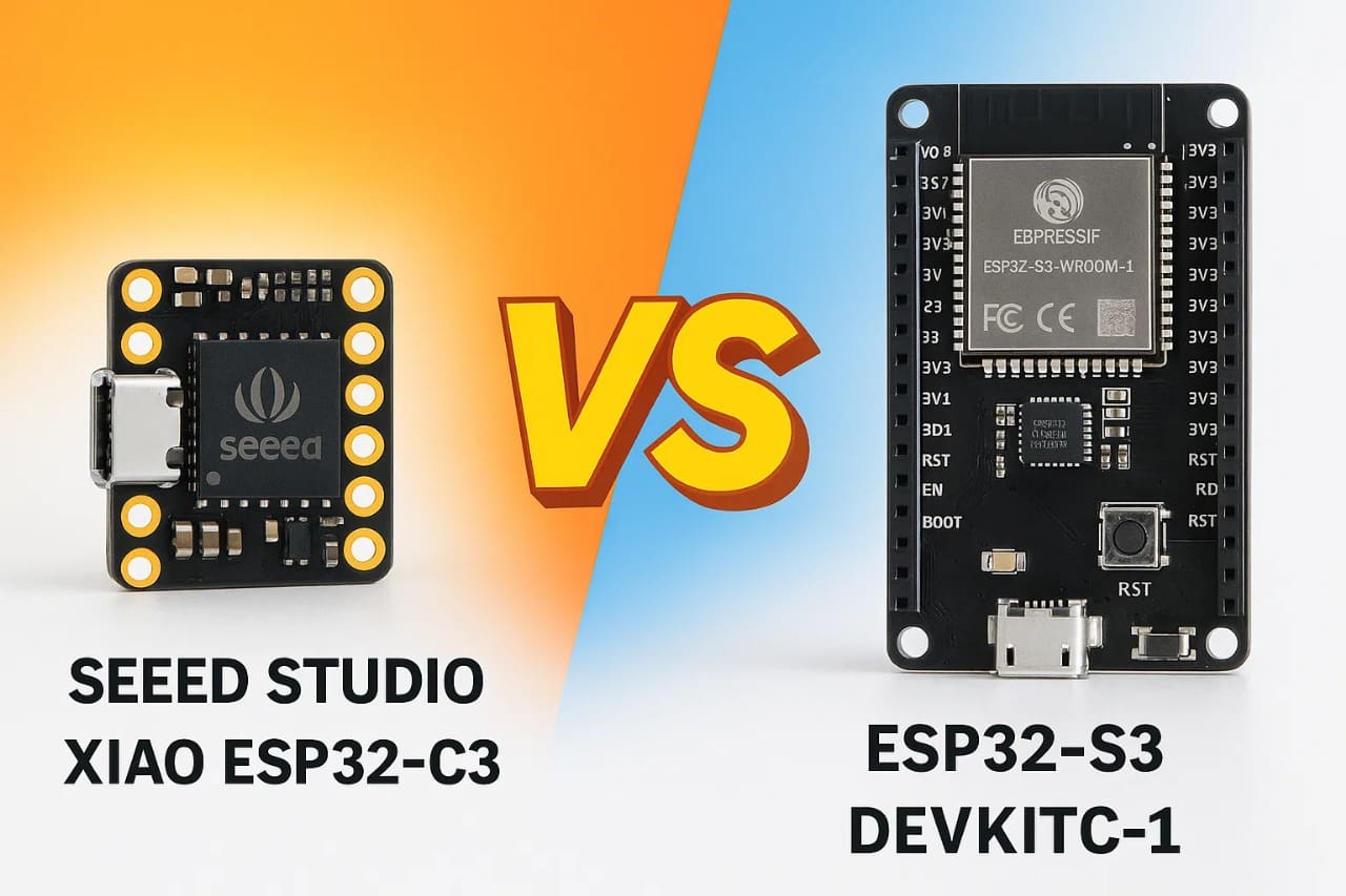
During this week, I worked with several teammates to compare different ESP32 boards,
specifically the XIAO ESP32-C3 and the ESP32-S3 DevKitC-1.
It was very helpful to see how each board performed under the same simulation and
programming conditions. Personally, I really liked the XIAO board —
it’s powerful and extremely compact, making it perfect for small, wearable, or
space-limited projects.
However, this hands-on comparison also helped me realize that the XIAO may not be
the best fit for my final project. I need more GPIOs, and I want the ability
to scale the system with future features like display output, sensors, or
connectivity modules. The ESP32-S3 offers more power, more flexibility, and a much
higher
number of I/O pins, making it ideal for a more complex and scalable embedded system.
Having the chance to discuss and test these differences with others clarified many
of my doubts and helped me understand not just the specs, but also how those specs
translate into real limitations or possibilities in an actual project.
Datasheet Highlights
As part of the assignment, I reviewed the datasheets of both microcontrollers I worked with: the XIAO ESP32-C3 and the ESP32-S3 DevKitC-1. This helped me better understand their internal architecture, communication capabilities, pinout differences, and power features.
-
XIAO ESP32-C3: Compact board using the ESP32-C3 chip (RISC-V
single-core at 160MHz),
with built-in USB, Wi-Fi and BLE 5.0, and limited but sufficient GPIOs for basic
projects.
📄 View ESP32-C3 Datasheet -
ESP32-S3 DevKitC-1: Powerful development board based on the
dual-core Xtensa LX7 at 240MHz,
with AI acceleration, more GPIOs, better peripheral support, and USB OTG.
📄 View ESP32-S3 Datasheet
One of the most useful insights was learning that both boards support Bluetooth Low Energy (BLE), which is optimized for short and efficient data communication rather than long data streams like Bluetooth Classic. BLE allows devices to stay connected with minimal energy usage, making it ideal for wearable and IoT applications. This explains why BLE libraries behave differently and why understanding the protocol matters when planning embedded systems.
Program Development
Develop an embedded system capable of detecting the proximity of objects using an ultrasonic sensor (HC-SR04) and generating a sound response with a buzzer when the measured distance falls below a defined threshold. This system will be implemented using the XIAO ESP32-C3 and ESP32-S3 DevKitC-1 boards, allowing for a comparison of their performance under the same conditions.
Pin Configuration Table
| Function | XIAO ESP32-C3 | ESP32-S3 DevKitC-1 |
|---|---|---|
| Trigger (HC-SR04) | GPIO 2 | GPIO 17 |
| Echo (HC-SR04) | GPIO 3 | GPIO 16 |
| Buzzer (Active) | GPIO 10 | GPIO 5 |
| VCC (HC-SR04) | 3.3V / 5V | 3.3V / 5V |
| GND (HC-SR04) | GND | GND |
Step-by-Step Guide for Wokwi Simulation
Follow these detailed steps to successfully simulate the ultrasonic sensor and buzzer with the XIAO ESP32-C3 or ESP32-S3 on the Wokwi platform:
1️⃣ Step 1: Access Wokwi Platform
Open your preferred web browser and go to the official Wokwi Platform. Wokwi is an online tool that allows you to simulate embedded systems circuits with microcontrollers and components like sensors, actuators, and LEDs. It's an excellent platform for testing and experimenting with hardware before physical implementation.
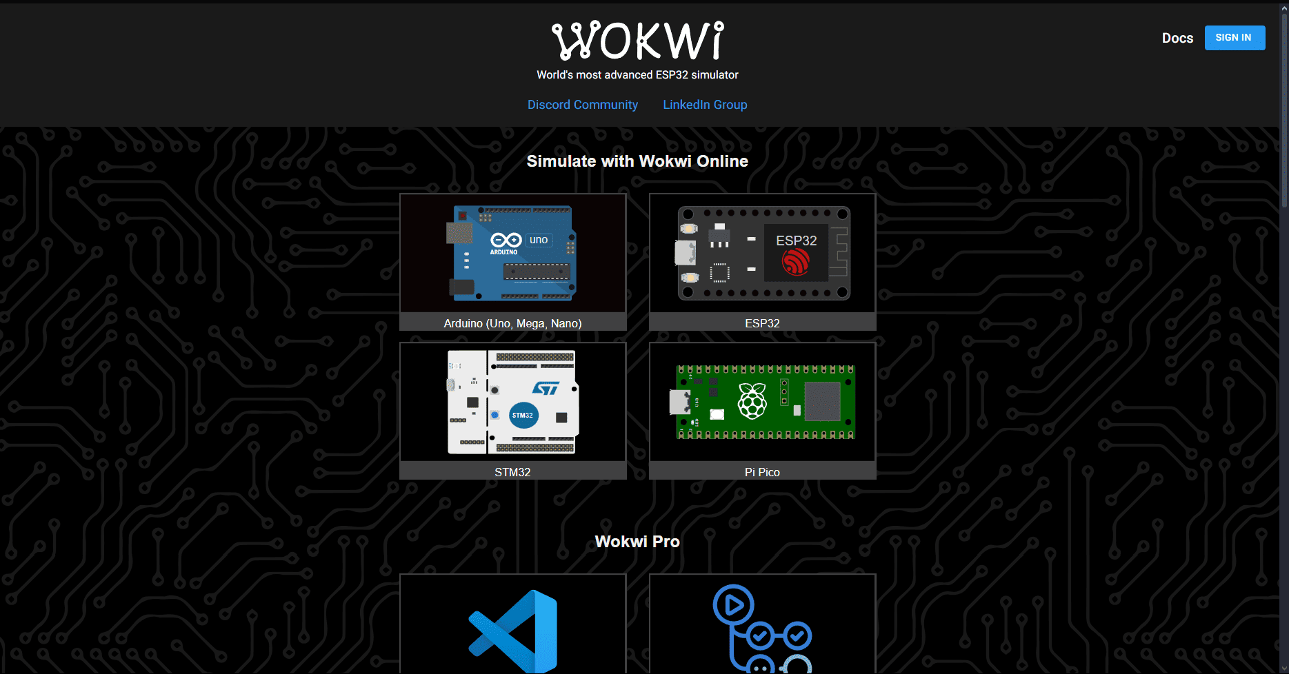
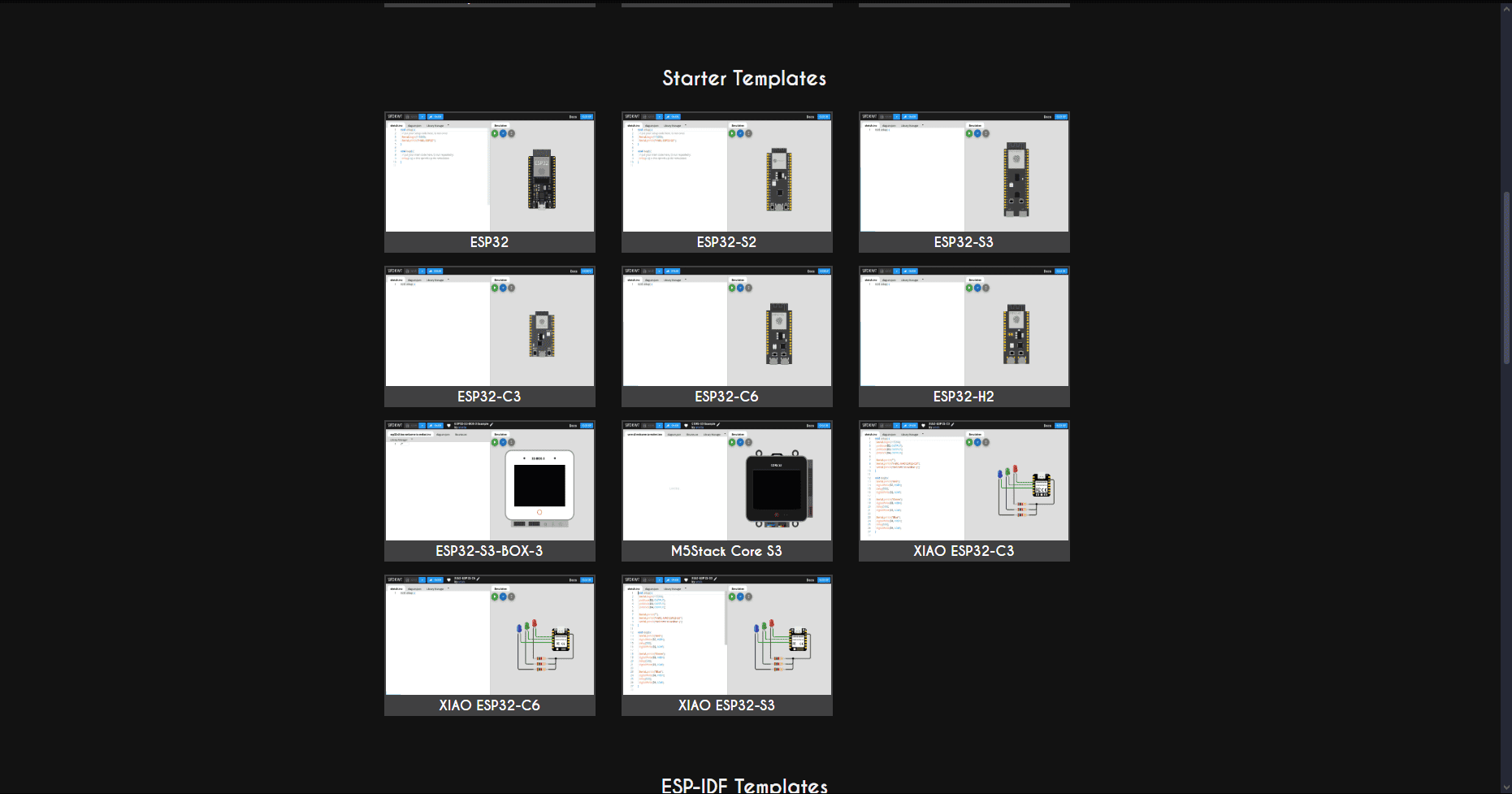
2️⃣ Step 2: Create a New Project
Once you are on the homepage of Wokwi, you will see a variety of options for different types of microcontrollers, including Arduino, ESP32, STM32, and Raspberry Pi Pico. Wokwi provides templates for each type of microcontroller to help you start quickly.
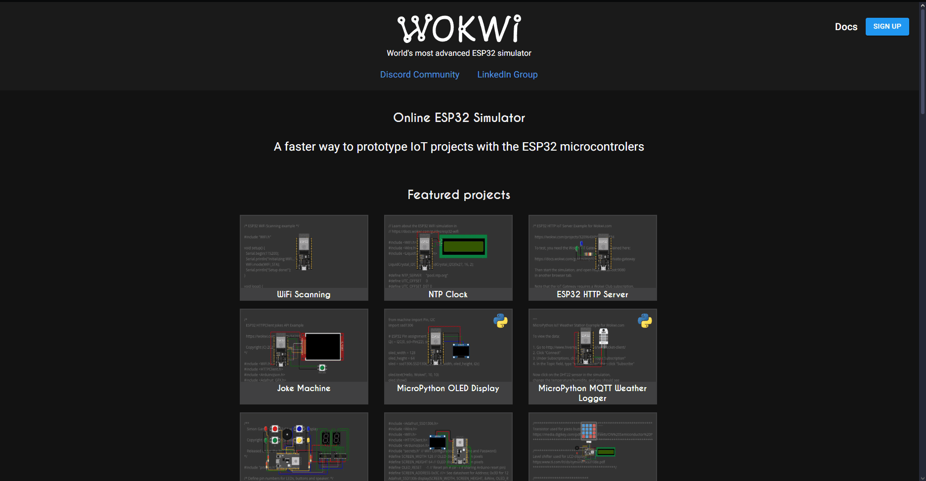
To begin, scroll down to the Starter Templates section. There, you’ll find pre-configured setups for different microcontrollers. You need to choose the ESP32 family, specifically the XIAO ESP32-C3 or ESP32-S3 templates.
After selecting a template, Wokwi will open a new workspace that is divided into two
sections:
- Left Panel: This is the code editor, where you will write and modify your code (Arduino or MicroPython).
- Right Panel: This is the simulation area, where you will see the microcontroller and all the connected components (like the HC-SR04 ultrasonic sensor and the buzzer).
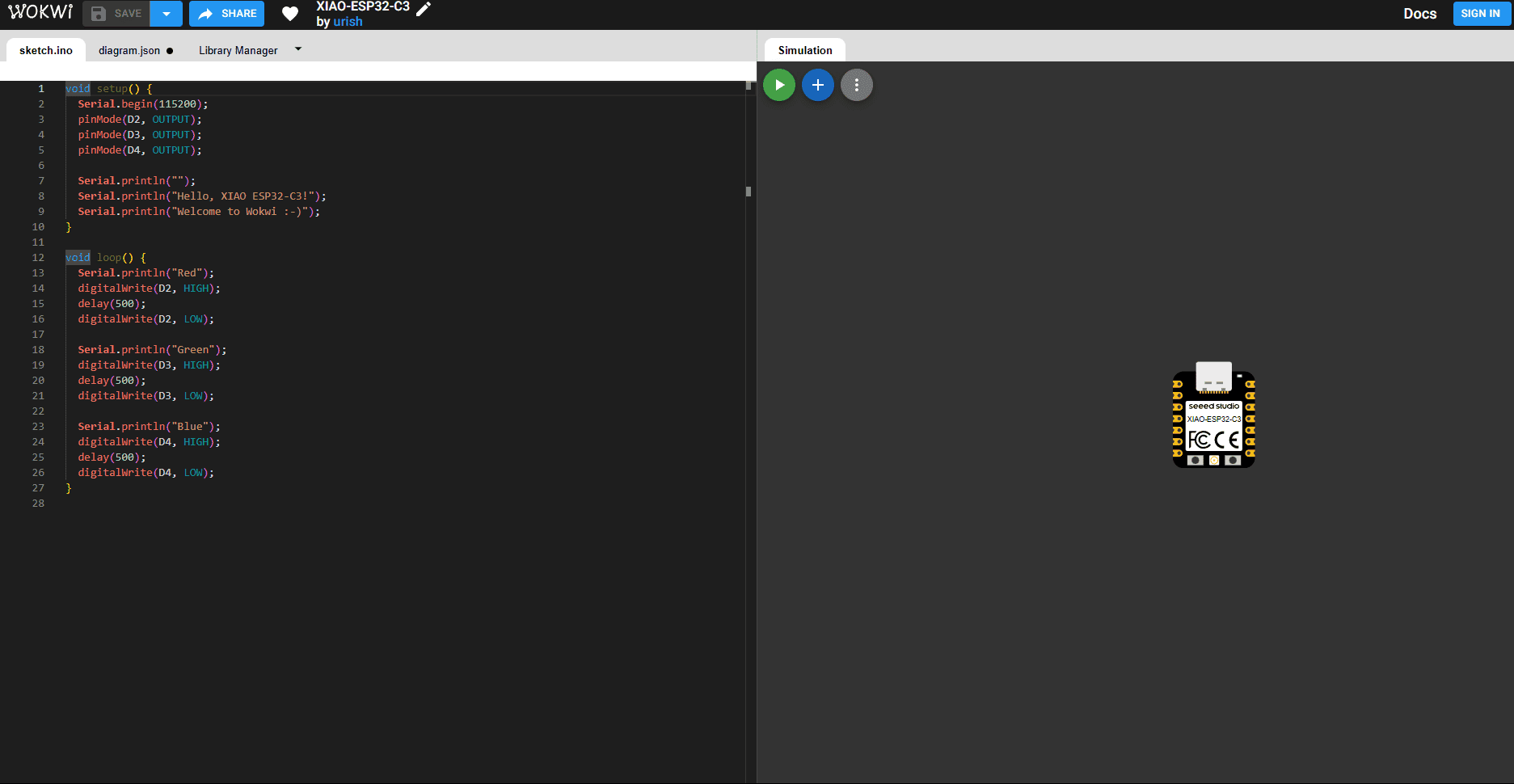
3️⃣ Step 3: Understanding the Workspace
In the simulation workspace, you will see the following key areas:
- Microcontroller Representation: The microcontroller will appear in the right panel, with labeled GPIO pins (such as GPIO 2, GPIO 3, etc.) for easy component connections.
- Simulation Control: At the top right of the simulation area, you
will find several buttons:
- Play (▶): Starts the simulation, allowing you to see how the components behave with your code.
- Add Component (+): Opens the component search bar, allowing you to add components like the HC-SR04 sensor and the buzzer.
- Options (⋯): Offers additional settings for adjusting the workspace, like zooming and other preferences.
- Code Area: On the left side, you will find the code editor. This is where you will write or paste your code to control the microcontroller and interact with the components. You will use this area to write logic for triggering the buzzer based on the ultrasonic sensor's distance measurement.
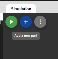
4️⃣ Step 4: Add the Components
To add the HC-SR04 ultrasonic sensor and the Active Buzzer to the simulation:
- Click the blue “+” button in the right panel to add components. This will open the component search bar.
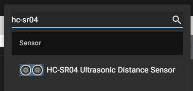
- In the search bar, type HC-SR04 and select HC-SR04 Ultrasonic Distance Sensor.
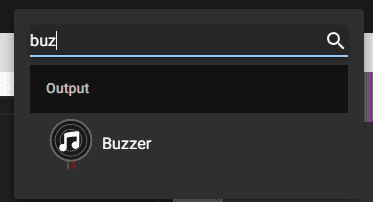
- Next, type Buzzer in the search bar and select Active Buzzer from the search results.
The components will appear in the workspace. You can drag and place them near the microcontroller for easy wiring.
5️⃣ Step 5: Select the Microcontroller Template
After selecting a new project template, Wokwi will show you several development board options. Choose one of the following options based on the microcontroller you are using:
- XIAO ESP32-C3: Select this template if you are using the XIAO ESP32-C3 microcontroller. The workspace will load with the microcontroller on the right side and the code editor on the left.
- ESP32-S3: Select this template if you are using the ESP32-S3 microcontroller. The workspace layout will be similar to the XIAO ESP32-C3 template, with the components and wiring available for editing.
The workspace will now be divided into two parts:
- Left Panel: This is where you will write and modify your Arduino or MicroPython code.
- Right Panel: The simulation area, where the microcontroller and all connected components are displayed for easy wiring and simulation.
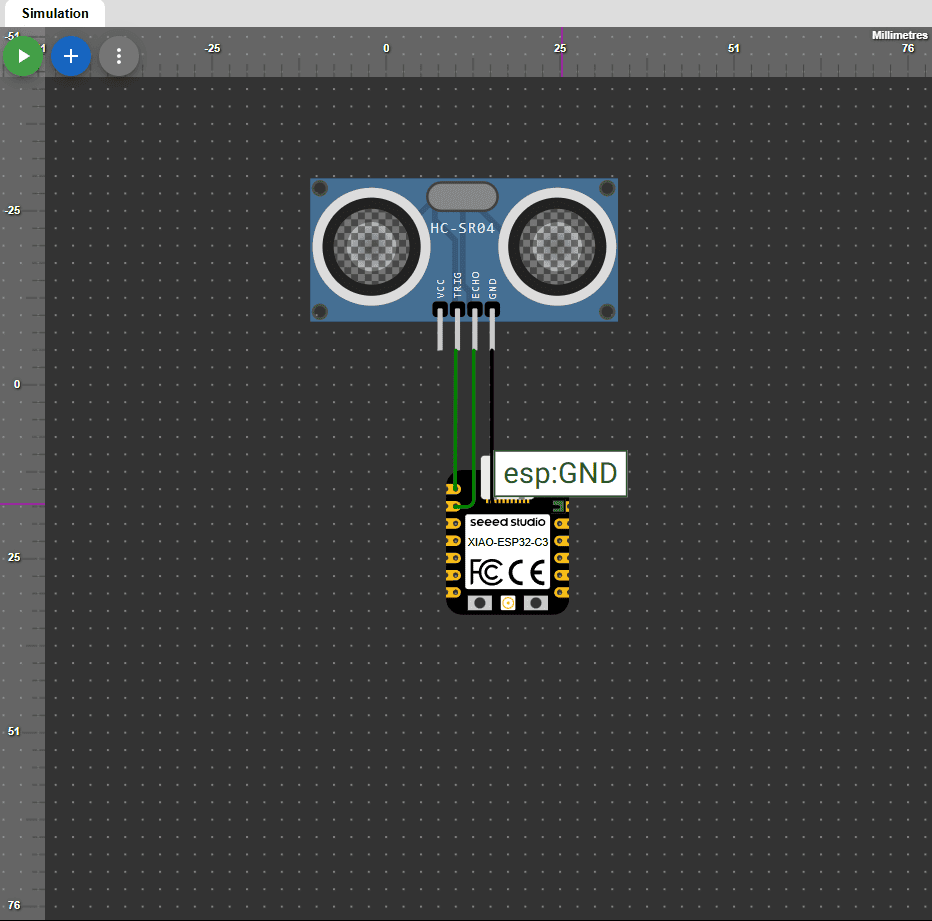
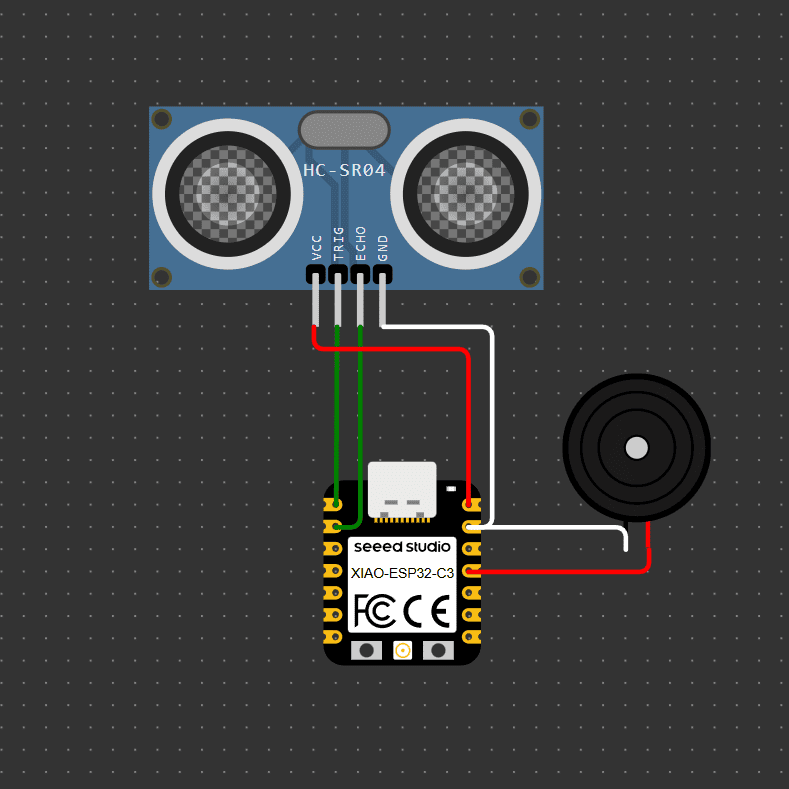
6️⃣ Step 6: Wiring the Components
Now that the components are in place, it’s time to wire them up based on the pin configuration. Use the following connections:
- Trigger (HC-SR04): Connect this pin to GPIO 2 on the XIAO ESP32-C3 or GPIO 17 on the ESP32-S3.
- Echo (HC-SR04): Connect this pin to GPIO 3 on the XIAO ESP32-C3 or GPIO 16 on the ESP32-S3.
- Buzzer: Connect this pin to GPIO 10 on the XIAO ESP32-C3 or GPIO 5 on the ESP32-S3.
- VCC (HC-SR04): Connect this to 3.3V or 5V depending on the microcontroller’s voltage options.
- GND (HC-SR04): Connect this to the GND pin of the microcontroller.
Make sure that all the connections are correct and that you have connected the power and ground pins of all components. Once everything is connected, you are ready for the next step: writing the code to control the components.
.png)
.png)
7️⃣ Step 7: Write the Code
Now that the components are correctly wired, it’s time to write the code. Here’s a breakdown of what your code will do:
- Initialize Pins: In the setup() function, you will define the Trigger and Echo pins for the HC-SR04 ultrasonic sensor and set the Buzzer pin as an output.
- Measure Distance: In the loop() function, use the pulseIn() function to calculate the time taken for the sound wave to travel to the object and back (this is the Echo pin). The Trigger pin will send a signal to initiate the pulse.
- Threshold Logic: If the distance measured by the ultrasonic sensor is below a certain threshold (e.g., 20 cm), activate the Buzzer to provide an audio alert.
- Display Output: Optionally, you can print the measured distance to the Serial Monitor for debugging or feedback.
Once you’ve written the code, click the Play (▶) button in the top-right corner of the workspace to run the simulation and verify that everything is working correctly. You should see the buzzer sound when an object is detected within the defined distance threshold.
CODE FOR THE XIAO ESP32-C3
Code Example 1: Ultrasonic Sensor with Xiao ESP32-C3
This program is designed specifically for the XIAO ESP32-C3 microcontroller. It uses an ultrasonic sensor to measure distance and activates a buzzer when an object is closer than 15 cm. The logic includes hysteresis to avoid false triggers due to noise.
All sections of the code are clearly commented to explain the purpose of each instruction and how the hardware behaves.
// Pin configuration
#define TRIG_PIN D0        // TRIG pin connected to GPIO2
#define ECHO_PIN D1        // ECHO pin connected to GPIO3
#define BUZZER_PIN D10     // Buzzer pin connected to GPIO10

// Variables
long duration;
float distance;
bool buzzerActive = false;

void setup() {
  Serial.begin(115200);              // Start serial monitor for debugging
  pinMode(TRIG_PIN, OUTPUT);         // Set TRIG as output
  pinMode(ECHO_PIN, INPUT);          // Set ECHO as input
  pinMode(BUZZER_PIN, OUTPUT);       // Set buzzer as output
  digitalWrite(BUZZER_PIN, LOW);     // Make sure buzzer starts off
}

void loop() {
  // Send ultrasonic pulse
  digitalWrite(TRIG_PIN, LOW);
  delayMicroseconds(2);
  digitalWrite(TRIG_PIN, HIGH);
  delayMicroseconds(10);
  digitalWrite(TRIG_PIN, LOW);

  // Measure ECHO duration
  duration = pulseIn(ECHO_PIN, HIGH);
  distance = (duration * 0.0343) / 2;   // Convert time to distance in cm

  Serial.print("Distance: ");
  Serial.print(distance);
  Serial.println(" cm");

  // Reject invalid readings (e.g., noise or out-of-range values)
  if (distance <= 0 || distance > 400) {
    Serial.println("Invalid reading");
    digitalWrite(BUZZER_PIN, LOW);
    return;
  }

  // Hysteresis logic for buzzer control:
  // Activate buzzer only when distance is less than 15 cm
  // Deactivate when it's greater than 20 cm (avoids flickering)
  if (distance > 0 && distance < 15) {
    buzzerActive = true;
  } else if (distance > 20) {
    buzzerActive = false;
  }

  // Beeping logic if buzzer is active
  if (buzzerActive) {
    digitalWrite(BUZZER_PIN, HIGH);
    delay(100);
    digitalWrite(BUZZER_PIN, LOW);
    delay(100);
  } else {
    digitalWrite(BUZZER_PIN, LOW);
  }

  delay(300); // Small delay before next reading
}
CODE FOR THE ESP32-S3
Code Example 2: Ultrasonic Sensor with ESP32-S3 DevKit
This second version targets the ESP32-S3 DevKitC-1. It shares the same logic as the Xiao version but adapts to different GPIO pins. The program measures distance with an ultrasonic sensor and activates a buzzer under threshold conditions, with all operations documented through comments.
Using two boards for the same logic helps understand the flexibility and adaptation needed across different microcontroller architectures.
// Pin configuration
#define TRIG_PIN 4         // TRIG pin connected to GPIO0
#define ECHO_PIN 5         // ECHO pin connected to GPIO1
#define BUZZER_PIN 10      // Buzzer connected to GPIO10

// Variables
long duration;
float distance;
bool buzzerActive = false;

void setup() {
  Serial.begin(115200);              // Start serial communication
  pinMode(TRIG_PIN, OUTPUT);         // TRIG set as output
  pinMode(ECHO_PIN, INPUT);          // ECHO set as input
  pinMode(BUZZER_PIN, OUTPUT);       // BUZZER set as output
  digitalWrite(BUZZER_PIN, LOW);     // Ensure buzzer is off initially
}

void loop() {
  // Send ultrasonic pulse
  digitalWrite(TRIG_PIN, LOW);
  delayMicroseconds(2);
  digitalWrite(TRIG_PIN, HIGH);
  delayMicroseconds(10);
  digitalWrite(TRIG_PIN, LOW);

  // Read echo duration
  duration = pulseIn(ECHO_PIN, HIGH);
  distance = (duration * 0.0343) / 2;   // Convert time to cm

  Serial.print("Distance: ");
  Serial.print(distance);
  Serial.println(" cm");

  // Filter invalid readings
  if (distance <= 0 || distance > 400) {
    Serial.println("Invalid reading");
    digitalWrite(BUZZER_PIN, LOW);
    return;
  }

  // Hysteresis logic to activate buzzer
  if (distance > 0 && distance < 15) {
    buzzerActive = true;
  } else if (distance > 20) {
    buzzerActive = false;
  }

  // Intermittent beep
  if (buzzerActive) {
    digitalWrite(BUZZER_PIN, HIGH);
    delay(100);
    digitalWrite(BUZZER_PIN, LOW);
    delay(100);
  } else {
    digitalWrite(BUZZER_PIN, LOW);
  }

  delay(300);  // Delay before next cycle
}
8️⃣ Step 8: Run the Simulation
Once you’ve written the code and connected all the components, it’s time to test the simulation. Click the Play (▶) button at the top right of the workspace to start the simulation.
The simulation will run, and you will be able to see how the ultrasonic sensor detects objects. If the distance is below the threshold you’ve set in your code, the buzzer will sound to alert you.
The Wokwi platform will show the results in the simulation window. If everything is correct, you should see the distance being measured in real-time and hear the buzzer sound when the object is too close.
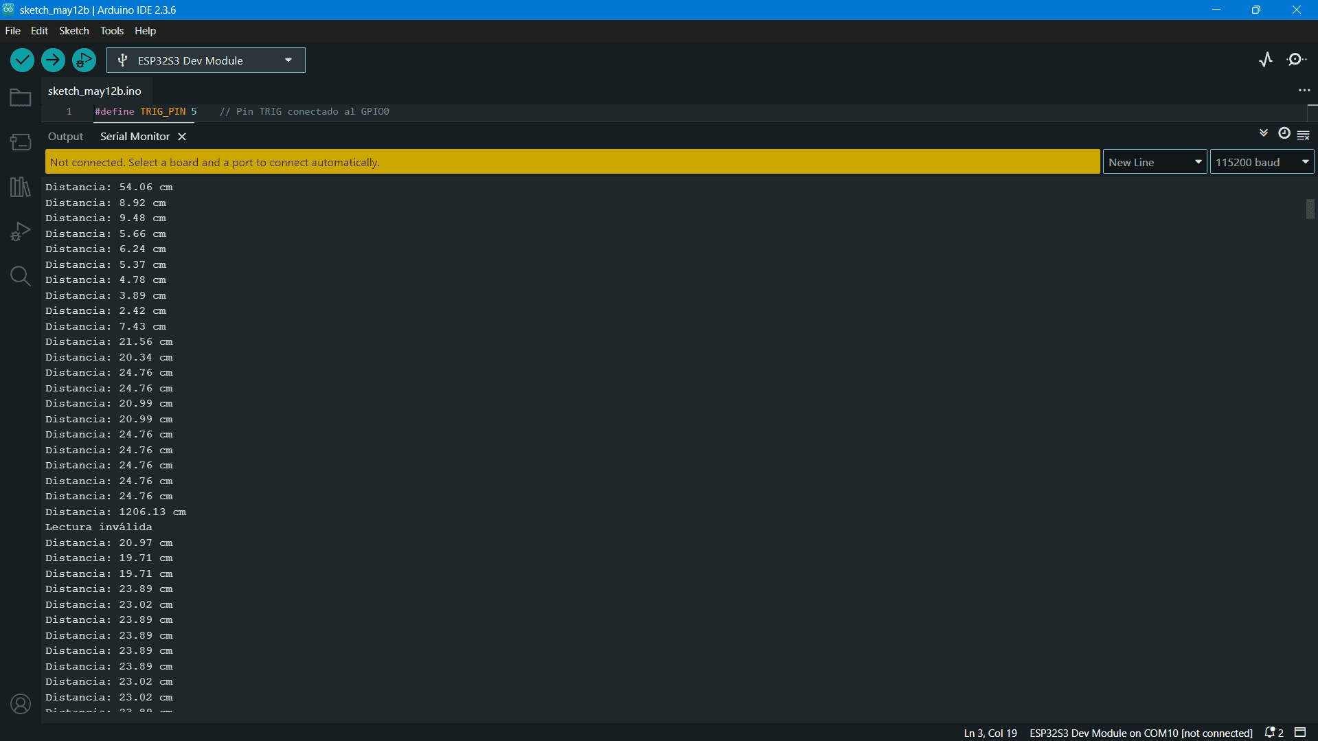
9️⃣ Step 9: Check the Serial Monitor
In order to see the real-time distance measurements from the ultrasonic sensor, you can open the Serial Monitor in Wokwi. This will give you feedback on the sensor’s readings as it detects objects.
To view the Serial Monitor, click on the Monitor tab at the top of the workspace (near the simulation control buttons). This will allow you to see the distance data printed by the microcontroller in real-time.
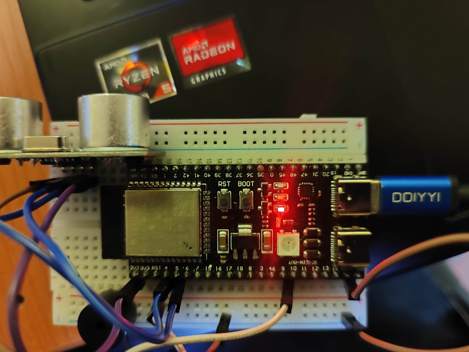
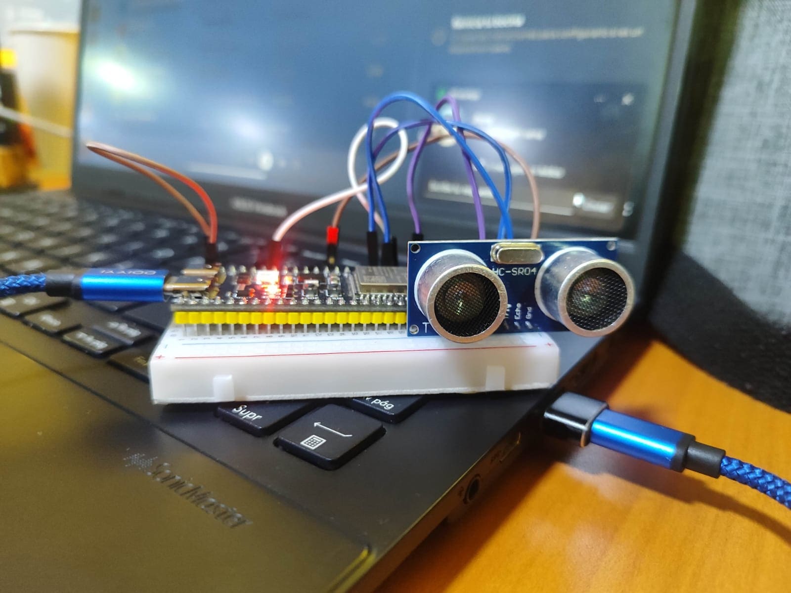
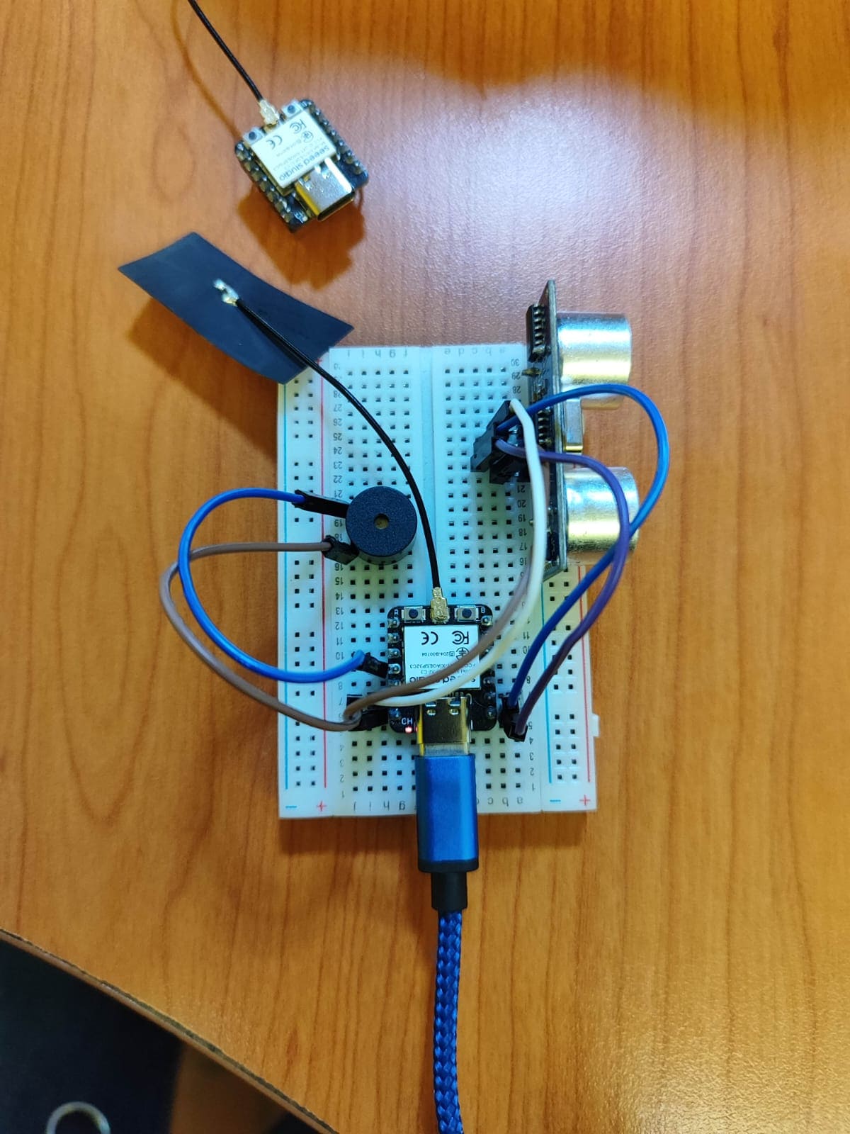
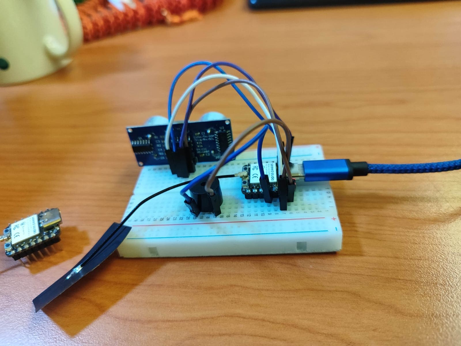
🔟 Step 10: Implement the System on Physical Hardware
After testing the simulation and confirming that everything is working as expected, you can move on to implementing the system with physical hardware.
Start by connecting the components (HC-SR04 sensor, buzzer, and the microcontroller) according to the same pin configuration used in the simulation. Make sure to connect the VCC and GND pins correctly.
If you are using the XIAO ESP32-C3, make sure that when you upload the code, you press the Boot button on the microcontroller to enter programming mode. This is necessary to allow the code to be uploaded.
For the ESP32-S3, you don’t need to press any buttons to enter programming mode. Simply ensure that you’ve selected the correct board and port in the Arduino IDE, and you are ready to upload the code.
|
ESP32-S3
|
|
|
XIAO ESP32-C3
|
|
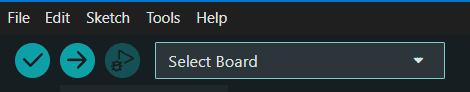
1️⃣1️⃣ Step 11: Code Upload and Testing on Arduino IDE
To upload the code from Wokwi to the Arduino IDE, follow these steps:
- Install Libraries: Before uploading the code, make sure to check if the required libraries (like HC-SR04) are installed. In the Arduino IDE, go to the Sketch > Include Library > Manage Libraries menu, and search for the HC-SR04 library. If it’s not installed, click Install.
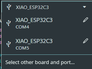
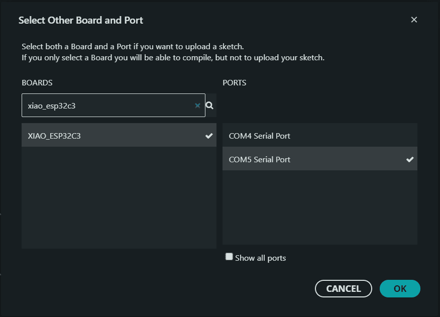
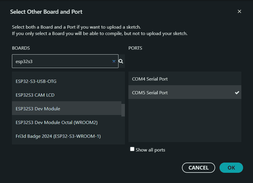
- Set the Board and Port: In the Arduino IDE, go to Tools > Board and select the appropriate board (e.g., XIAO ESP32-C3 or ESP32-S3). Then, select the correct Port under Tools > Port.
- Upload Code: Click the Upload button (the arrow icon) to send the code to the microcontroller. If you are using the XIAO ESP32-C3, press the Boot button to enter programming mode. For the ESP32-S3, no additional steps are needed.
|
SET UP ARDUINO IDE
|
|
|
|
1️⃣2️⃣ Step 12: Debugging and Final Testing
After uploading the code to the microcontroller, you can test the system by opening the Serial Monitor in the Arduino IDE. You should see the distance readings being printed as the ultrasonic sensor measures the distance.
If the buzzer sounds when the distance is below the threshold, it indicates that everything is working as expected. If not, check your wiring and code for any errors.
1️⃣3️⃣ Step 13: Enjoy Your Working System!
After debugging and testing the system, you now have a working ultrasonic proximity detection system. Congratulations! You’ve successfully used Wokwi to simulate your project and then implemented it on a physical microcontroller.
You can now use this system in a variety of applications, such as object detection, obstacle avoidance in robots, or even automatic lighting control systems.
XIAO ESP32-C3 RESULT
ESP32-S3 RESULT
Conclusions
Personal conclusions from this week
This week was a balance between applying previous knowledge and refining technical details I hadn’t explored deeply before. I focused on comparing two ESP32 development boards: the ESP32-S3 and the XIAO ESP32-C3. Although I had used ESP32s before, I made sure to carefully study their datasheets and test configurations using Wokwi before moving on to physical hardware.
One of the key advantages was using simulation. I built a test system with an ultrasonic sensor and a buzzer, validated it virtually, and then replicated it in real hardware. This step-by-step method helped prevent wiring mistakes and protected the components.
⚠️ Troubleshooting: Native USB Programming Issue
While testing the XIAO ESP32-C3, I encountered an issue where the board wouldn’t enter programming mode automatically. At first, I assumed the board was defective.
After consulting the official documentation, I discovered that boards with native USB (like the C3) require a manual process: pressing the BOOT button (and sometimes the RESET button) to enable upload mode. Once I applied this method, the upload worked perfectly.
This incident reminded me how essential it is to consult documentation, even for known devices. What seemed like a hardware failure was simply a misunderstood behavior specific to native USB boards.
This experience reinforced how critical it is to read technical documentation, even when working with familiar hardware. A small detail like entering programming mode can become a major blocker if misunderstood. Thanks to previous experience, simulator tools, and careful reading, I managed to complete the week’s assignment successfully: analyzing specs, simulating circuits, writing and testing the code, and assembling everything physically.
Overall, I feel better prepared to integrate sensors and actuators on different ESP32 boards, and I now understand the importance of knowing the specific upload behaviors of each model.