
I had a meeting with Armando Calcina, where I shared the activities we needed to complete. I updated him on my progress and explained the tasks he needed to complete to catch up with the academy, since I'm a little more advanced. Later, I'll meet with Jhonatan Cortes to update him and involve him in the work with us.
For this group project, I have reviewed two microcontrollers, the RP2040 and the ESP32-C, conducting a detailed comparison to identify their differences, potential, and architectures.
Here you can view and download the data sheet.
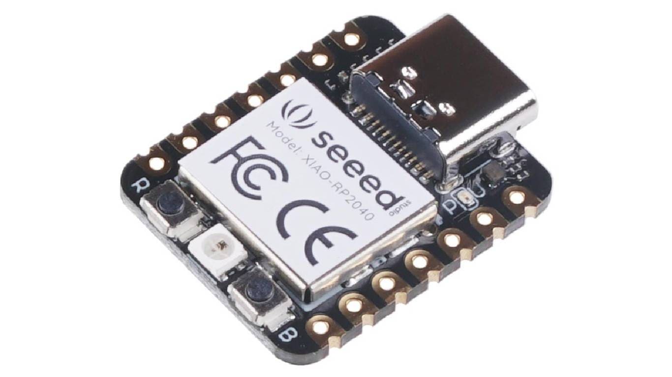
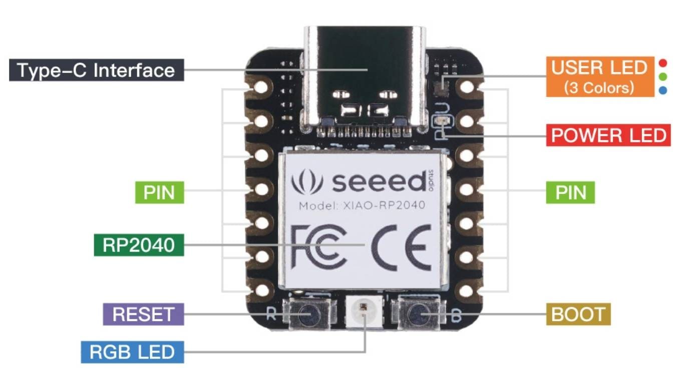
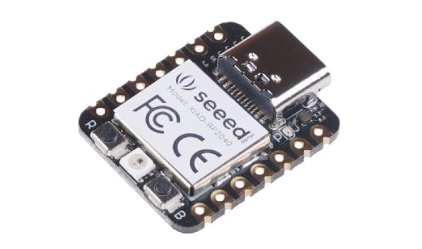
The Xiao RP2040 board is a compact development board based on the RP2040 microcontroller from Raspberry Pi. It is designed to offer high performance in a small form factor, ideal for low-power electronics projects.
This board features a dual-core ARM Cortex-M0+ microcontroller running at 133 MHz, and provides 264 KB of SRAM for fast and efficient data storage. The external flash memory of 16 MB allows for additional storage for larger projects.
With 26 GPIO pins (digital input/output), it supports various functions such as PWM, SPI, I2C, and UART, making it highly versatile for controlling and communicating with other devices. It also includes a 12-bit analog-to-digital converter (ADC) for reading analog signals.
The Xiao RP2040 is especially designed to simplify programming and is compatible with development environments like Arduino and MicroPython, allowing users to easily and quickly create applications. The board is perfect for applications in robotics, automation, Internet of Things (IoT), and other projects that require an efficient and small microcontroller.
(This data is taken from ChatGPT.)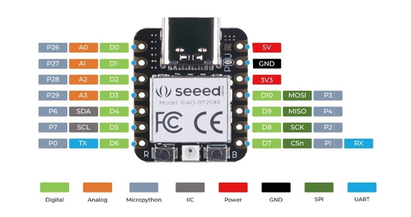
This is the typical workflow for developing with the RP2040, making it easier to program and load firmware onto its integrated architecture.
| Item | Value |
| CPU | Dual-core ARM Cortex M0+ processor up to 133MHz |
| Flash Memory | 2MB |
| SRAM | 264KB |
| Digital I/O Pins | 11 |
| Analog I/O Pins | 4 |
| PWM Pins | 11 |
| I2C interface | 1 |
| SPI interface | 1 |
| UART interface | 1 |
| Power supply and dowloading interface | Type-C |
| Power | 3.3V/5V DC |
| Dimensions | 21x17.8x3.5mm |
                        from machine import Pin, Timer
                        ledAzul = Pin(25, Pin.OUT)
                        ledRojo = Pin(17, Pin.OUT)
                        ledVerde = Pin(16, Pin.OUT)

                        Counter = 0
                        Fun_Num = 0

                        def fun(tim):
                            global Counter
                            Counter = Counter + 1
                            print(Counter)
                            ledVerde.value(1)
                            ledRojo.value(1)
                            ledAzul.value(Counter%2)


                        tim = Timer(-1)
                        tim.init(period=1000, mode=Timer.PERIODIC, callback=fun)
Next, I will provide a code to control the LEDs on the Xiao RP2040.
Now, I’m running a test for blinking LED lights using multiple lights connected to specific pins. In this case, I have three LEDs: one blue, one red, and one green, and the code is designed to make the blue LED blink periodically.
Here you can view and download the data sheet.
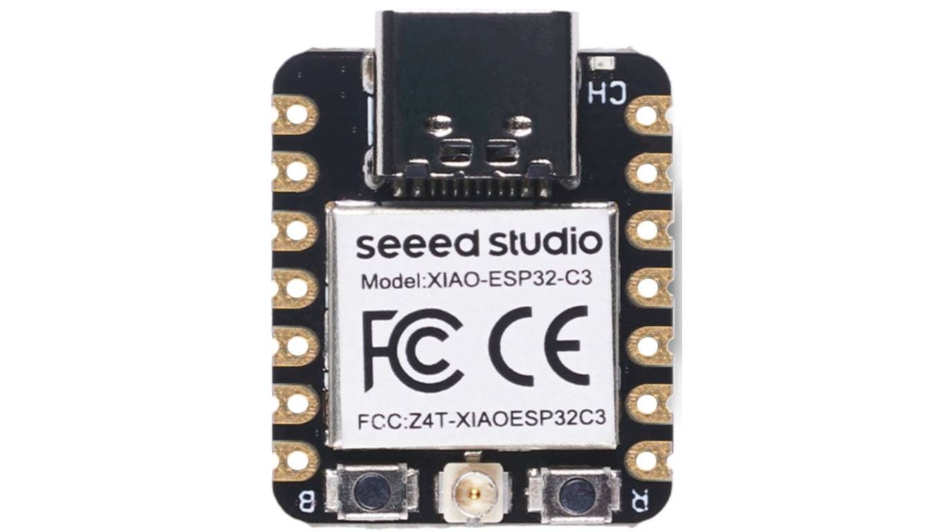
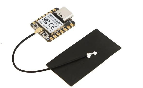
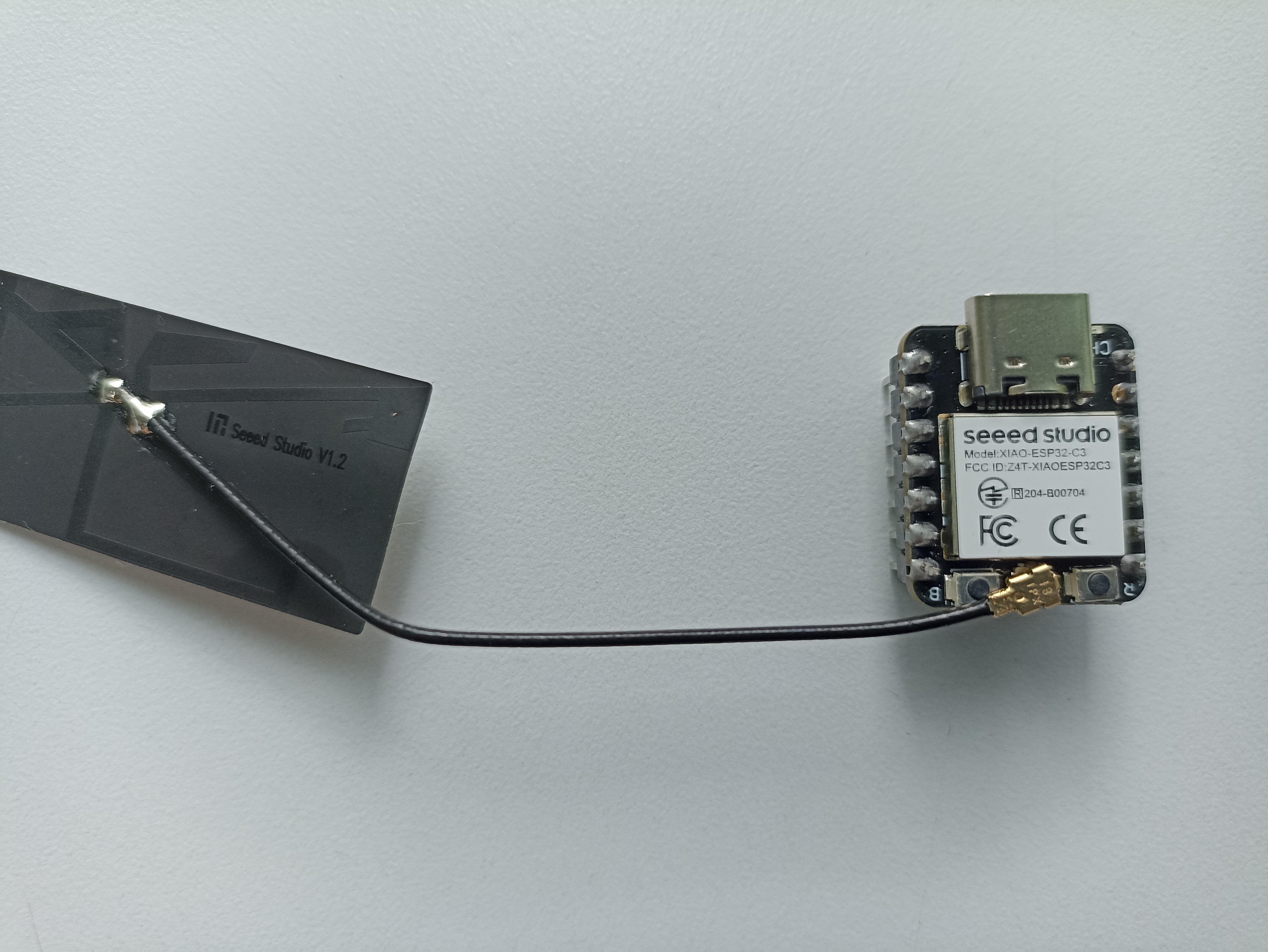
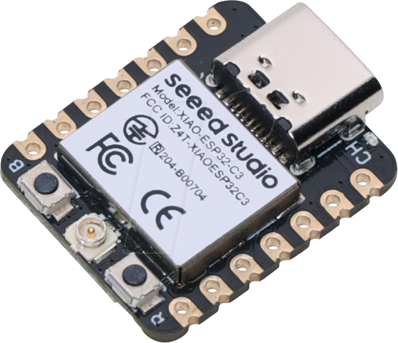
Seeed Studio XIAO ESP32C3 is an IoT mini development board based on the Espressif ESP32-C3 WiFi/Bluetooth dual-mode chip. ESP32-C3 is a 32-bit RISC-V CPU, which includes an FPU (Floating Point Unit) for 32-bit single-precision arithmetic with powerful computing power. It has excellent radio frequency performance, supporting IEEE 802.11 b/g/n WiFi, and Bluetooth 5 (BLE) protocols. This board comes included with an external antenna to increase the signal strength for your wireless applications. It also has a small and exquisite form-factor combined with a single-sided surface-mountable design. It is equipped with rich interfaces and has 11 digital I/O that can be used as PWM pins and 3 analog I/O that can be used as ADC pins. It supports four serial interfaces such as UART, I2C and SPI.
This workflow enables efficient development and uploading of projects to the ESP32-C3, whether for IoT applications or embedded systems.
This summary highlights the essential components of the XIAO ESP32-C3, making it ideal for IoT and embedded projects.
from machine import Pin
from time import sleep

# Intentar con el pin GPIO 0 (puede ser otro dependiendo de la placa)
led = Pin(10, Pin.OUT)

while True:
    led.value(1)  # Encender el LED (1 = HIGH)
    sleep(1)      # Esperar 1 segundo
    led.value(0)  # Apagar el LED (0 = LOW)
    sleep(1)      # Esperar 1 segundo
With the help of ChatGPT, I have created a code to activate an LED using GPIO pin 10 on the XIAO ESP32-C3 microcontroller.
Now, with the programming, I'm doing a simple test to see how to turn an LED on and off.
| Aspect | RP2040 (XIAO RP2040) | ESP32-C3 |
| Architecture | ARM Cortex-M0+ (Dual Core, 133 MHz) | RISC-V 32-bit (160 MHz) |
| Connectivity | USB, UART, SPI, I2C | Wi-Fi, Bluetooth 5.0, UART, SPI, I2C |
| Development Environment | Arduino IDE, Thonny (MicroPython) | Arduino IDE, ESP-IDF, MicroPython |
| Toolchain | Arduino Core for RP2040, MicroPython | Espressif IDF, Arduino Core, MicroPython |
| Programming Method | USB drag-and-drop (BOOTSEL), Thonny IDE | USB/UART flashing tools |
| Typical Use Case | Low-power, compact IoT projects | Wireless IoT, more advanced networking |
| Beginner-Friendliness | High – very user-friendly | Moderate – requires extra setup |
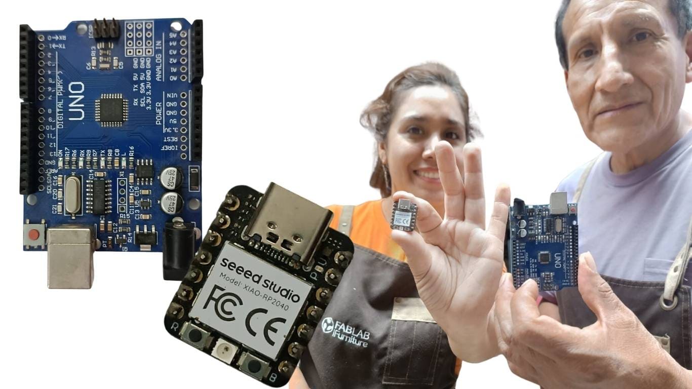
During this week of group work, I met with my partner Evelyn at the Fab Lab iForniture, located in the city of Lima, and also coordinated with her to research and make the respective comparisons of the microcontrollers that we had selected for our study. Each one was dedicated to the detailed analysis of a specific microcontroller; in my case, I chose the Seeed Studio XIAO ESP32C3, an IoT mini development board based on the Espressif ESP32-C3 and the XIAO RP2040.
| Aspect | XIAO ESP32-C3 | XIAO RP2040 |
|---|---|---|
| Architecture | RISC-V 32-bit (ESP32-C3) | ARM Cortex-M0+ (RP2040) |
| Common IDEs | Arduino IDE, PlatformIO, ESP-IDF | Arduino IDE, PlatformIO, Thonny, CircuitPython |
| Toolchain / Compiler | riscv32-esp-elf-gcc | arm-none-eabi-gcc |
| Supported Frameworks | Arduino, ESP-IDF, MicroPython | Arduino, Pico SDK, MicroPython, CircuitPython |
| USB Connection | USB-C, requires BOOT button for flashing | USB-C, mounts as USB drive (UF2) |
| Flashing Method | esptool.py, Arduino, PlatformIO | Drag-and-drop .uf2 file or upload via IDE |
| Recovery Mode | Hold BOOT + Reset to enter flash mode | Press BOOT while connecting USB |
| Typical Workflow (Arduino) | Write → Compile → Press BOOT → Upload | Write → Compile → Upload or drag UF2 |
| Driver Required | CH340 or CP210x (depending on USB chip) | Not always needed |
| Complexity Level | Medium | Low |
| Development Speed | High (PlatformIO or Arduino) | Very high (UF2 or MicroPython) |
| Official Documentation | Espressif Docs | Raspberry Pi Docs |
Seeed Studio XIAO ESP32C3 is an IoT mini development board based on the Espressif ESP32-C3 WiFi/Bluetooth dual-mode chip, featuring a 32-bit RISC-V CPU that delivers powerful computing performance with its efficient architecture. It has excellent radio frequency performance, supporting IEEE 802.11 b/g/n WiFi, and Bluetooth 5 (BLE) protocols. This board comes included with an external antenna to increase the signal strength for your wireless applications. It also has a small and exquisite form-factor combined with a single-sided surface-mountable design. It is equipped with rich interfaces and has 11 digital I/O that can be used as PWM pins and 3 analog I/O that can be used as ADC pins.
| Specification | Detail |
|---|---|
| Microcontroller | ESP32-C3, RISC-V 32-bit single-core |
| Clock Speed | 160 MHz |
| Flash Memory | 4 MB |
| RAM | 400 KB SRAM (plus 8 KB RTC RAM) |
| Connectivity | Wi-Fi 2.4 GHz (802.11 b/g/n), Bluetooth 5.0 LE |
| GPIO | 11 general-purpose I/O pins (I2C, UART, SPI, ADC, PWM, etc.) |
| ADC | 6 ADC channels, 12-bit |
| Operating Voltage | 3.3 V (powered by 5V via USB-C) |
| Power Consumption | Low power, supports deep sleep mode |
| Power Supply | 5 V via USB-C |
| Buttons | 1 BOOT button (for bootloader mode) |
| Programming | Supports Arduino IDE, PlatformIO, ESP-IDF, MicroPython |
| Compatibility | Compatible with Grove / Qwiic development boards (I2C) |
| USB Interface | USB-C (supports programming and power supply) |
The Seeed Studio XIAO RP2040 is as small as the Seeed Studio XIAO SAMD21 but it's more powerful. On one hand, it carries the powerful Dual-core RP2040 processor that can flexible clock running up to 133 MHz which is a low-power microcontrollers. On the Seeed Studio XIAO RP2040 there is also 264KB of SRAM, and 2MB of on-board Flash memory which can provide more program to save and run. On the other hand, this little board has good performance in processing but needs less power. All in all, it is designed in a tiny size as small as a thumb(21x17.8mm) and can be used for wearable devices and small projects.
| Specification | Detail |
|---|---|
| Microcontroller | RP2040, ARM Cortex-M0+ dual-core |
| Clock Speed | 133 MHz |
| Flash Memory | 2 MB |
| RAM | 264 KB SRAM |
| Connectivity | None (No Wi-Fi/Bluetooth) |
| GPIO | 26 general-purpose I/O pins (I2C, UART, SPI, ADC, PWM, etc.) |
| ADC | 3 ADC channels, 12-bit |
| Operating Voltage | 3.3 V (powered by 5V via USB-C) |
| Power Consumption | Low power, supports deep sleep mode |
| Power Supply | 5 V via USB-C |
| Buttons | 1 BOOT button (for bootloader mode) |
| Programming | Supports Arduino IDE, PlatformIO, MicroPython, CircuitPython |
| Compatibility | Compatible with many Raspberry Pi accessories and HATs |
| USB Interface | USB-C (supports programming and power supply) |
                        #define LED_PIN 13  // Define el pin del LED

                        void setup() {
                           pinMode(LED_PIN, OUTPUT); // Configura el pin como salida
                        }

                        void loop() {
                           digitalWrite(LED_PIN, HIGH); // Enciende el LED
                           delay(500);                  // Espera 500 ms
                           digitalWrite(LED_PIN, LOW);  // Apaga el LED
                           delay(500);                  // Espera 500 ms
                        }
A microcontroller (MCU) is like the "brain" of many electronic devices. Imagine it as a tiny computer built into one single chip. It's responsible for making decisions and controlling other components in real time, just like your brain tells your muscles what to do. These chips are commonly found in things like home appliances, robots, thermostats, medical equipment, or smart gadgets connected to the Internet (IoT).
Microcontrollers are programmed to follow a list of instructions. Once you load a program into it, it can perform tasks automatically, like turning on a light when it gets dark or sending data to your phone when it detects motion.
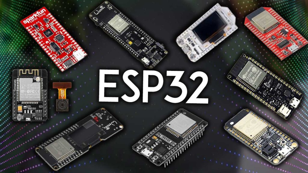
The ESP32 family was created by Espressif Systems, a company that makes affordable and powerful chips with built-in Wi-Fi and Bluetooth. These chips are very popular in the DIY and professional world because they are easy to use, powerful, and well documented. The ESP32 is an improvement of the older ESP8266 chip and comes in several versions for different needs.
🔗 Board Info: Getting Started with XIAO ESP32-C3
📄 Datasheet: View full ESP32-C3 Datasheet (PDF)
The XIAO ESP32-C3 is a compact board that uses the ESP32-C3 microcontroller. Think of it like a mini brain with built-in Wi-Fi and Bluetooth, designed for low-power and small-space projects like wearables or battery-powered sensors.
🔗 Board Info: Pinout & Specs – VCC-GND Studio
📄 Datasheet: View full ESP32-S3 Datasheet (PDF)
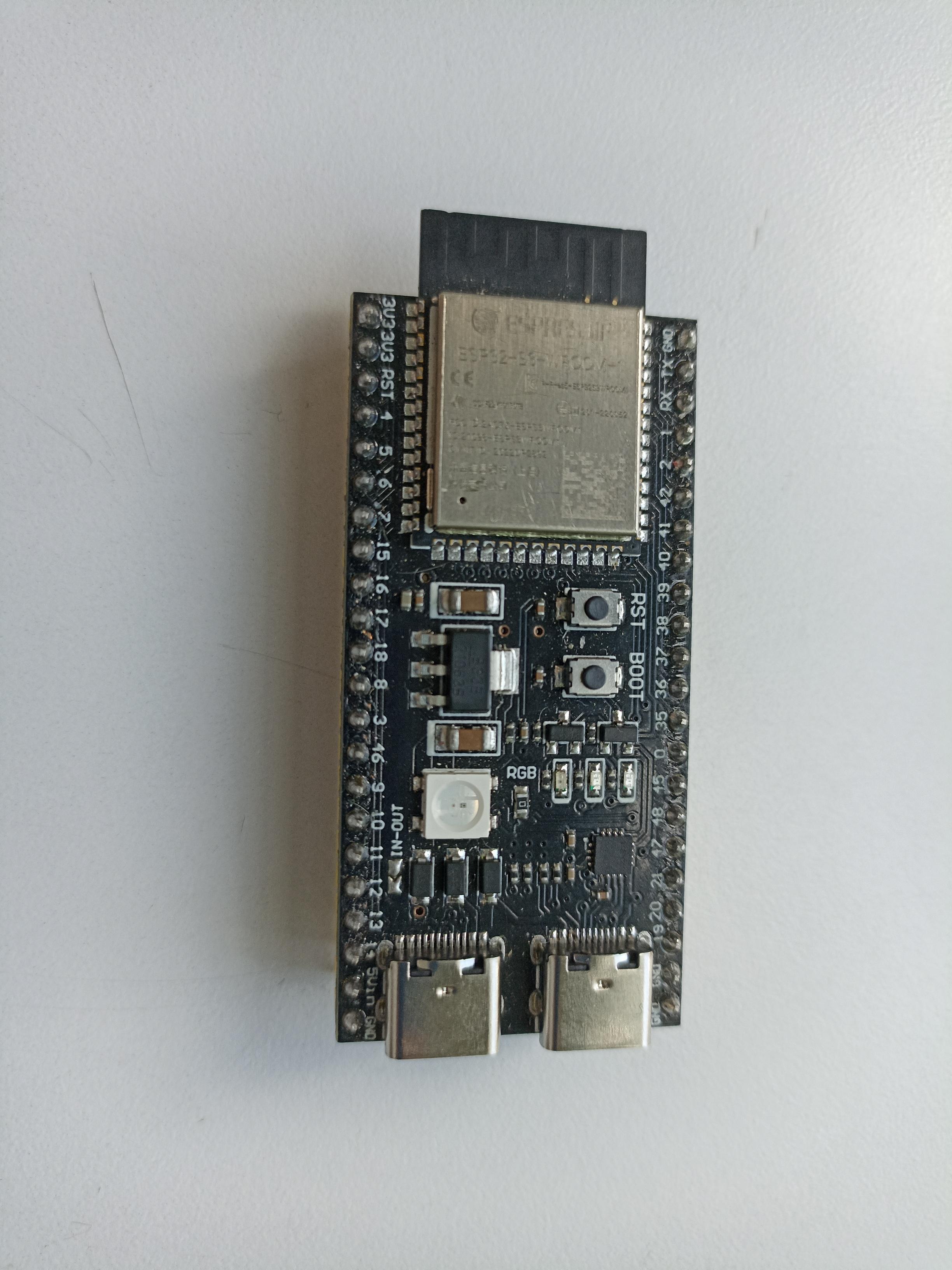
This board uses the ESP32-S3 chip, a much more powerful version designed for advanced applications like image recognition or AI on the edge — all while still offering Wi-Fi and Bluetooth.
| Characteristic | ESP32-C3 (XIAO) | ESP32-S3 (DevKitC-1) |
|---|---|---|
| Architecture | RISC-V Open Source | Xtensa LX7 High Performance |
| Number of Cores | 1 | 2 |
| Clock Speed | 160 MHz | 240 MHz |
| AI/ML Capabilities | No | Yes (SIMD, hardware-based AI) |
| USB | USB 2.0 Native | USB OTG (Host and Device) |
| Power Consumption | Low (ideal for batteries) | Moderate-High (depending on peripherals) |
| Advanced Security | Secure Boot, Flash Encryption | Equal or better, with accelerated encryption support |
| Usage Focus | Compact devices and low power consumption | Complex applications, AI, rich interfaces |
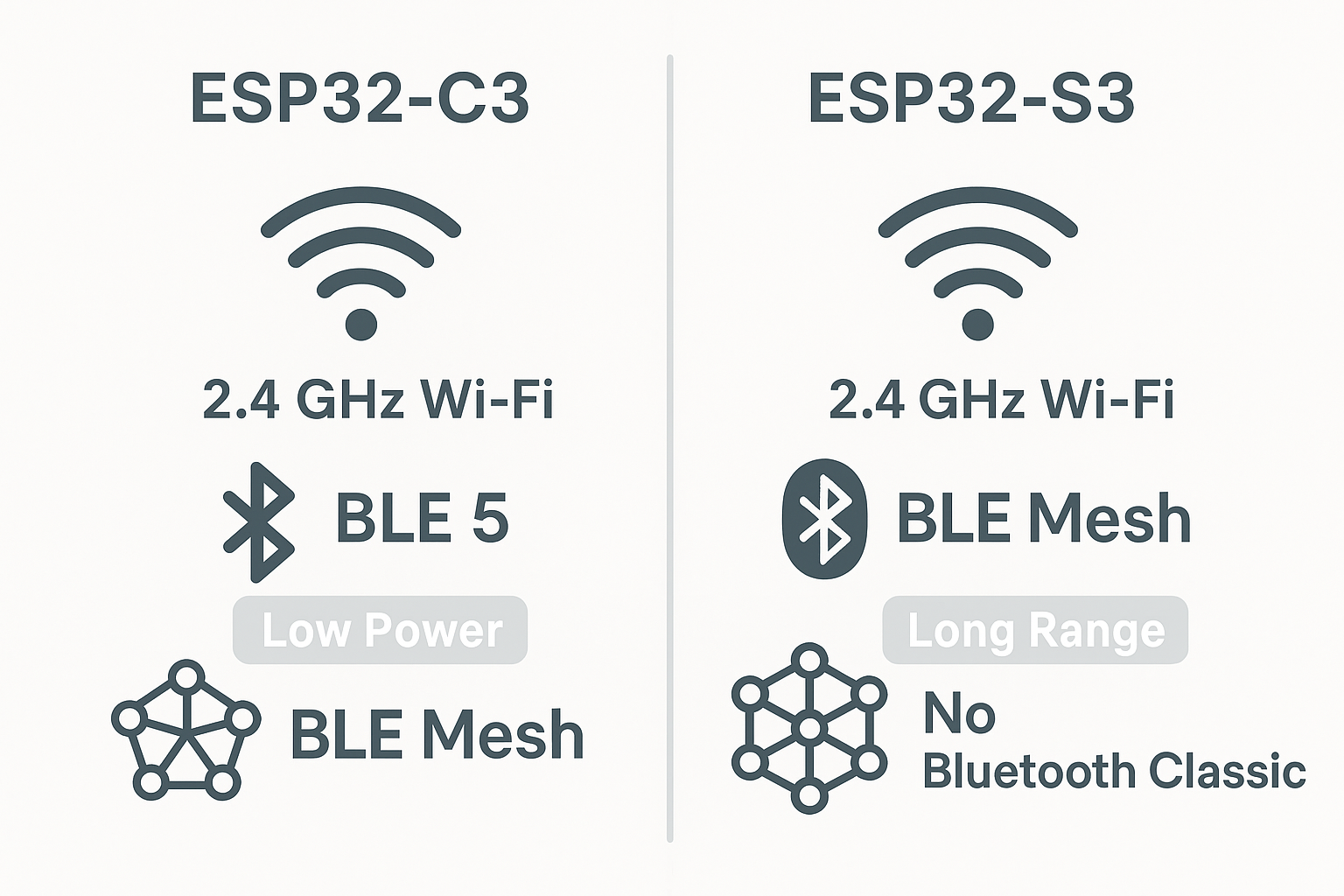
Visual overview of Wi-Fi and BLE features in ESP32-C3 and ESP32-S3
Both microcontrollers have built-in Wi-Fi and Bluetooth, perfect for wireless projects in IoT. However, there are some differences worth noting:
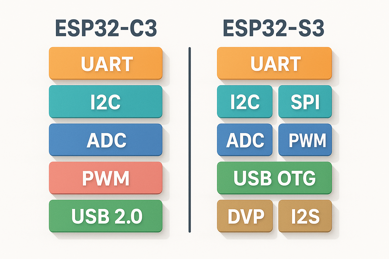
Comparison of interface capabilities: UART, SPI, I2C, ADC, PWM and USB OTG
These define how the board connects with external sensors, screens, and devices:
Some microcontrollers are not just for turning things on or off — they can also do things like detect faces in a picture or understand voice commands. That's what we call specialized processing. Here's how our two boards compare:
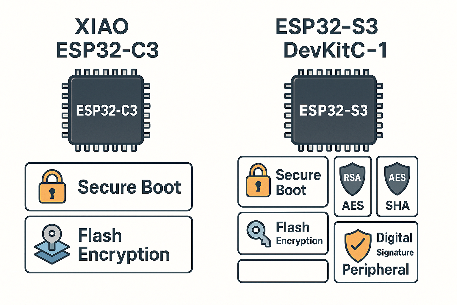
Security tools comparison: Flash Encryption, Secure Boot, RSA, HMAC
Security is important when your device stores private data or connects to the internet. Both boards come with built-in protection features:
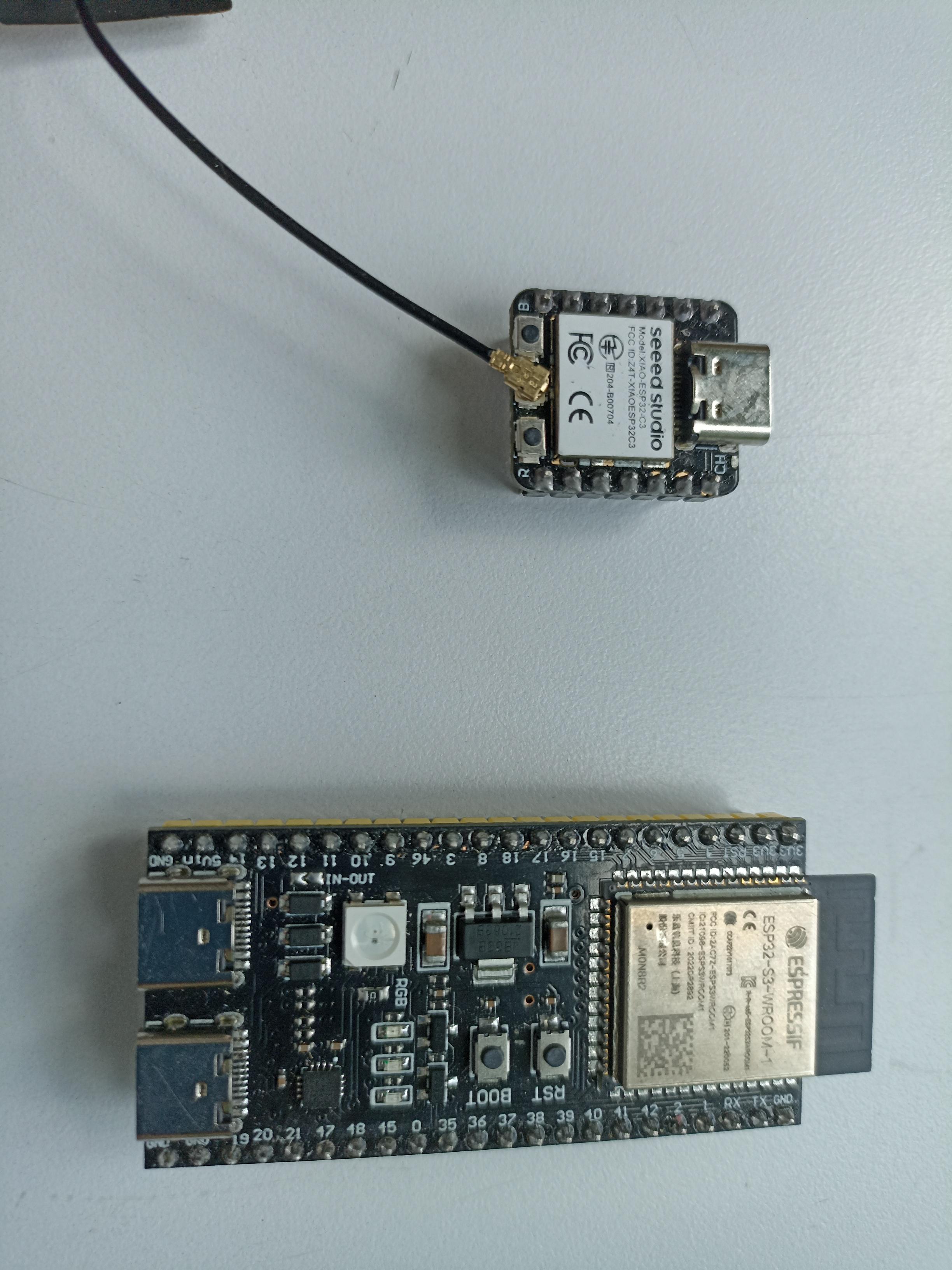
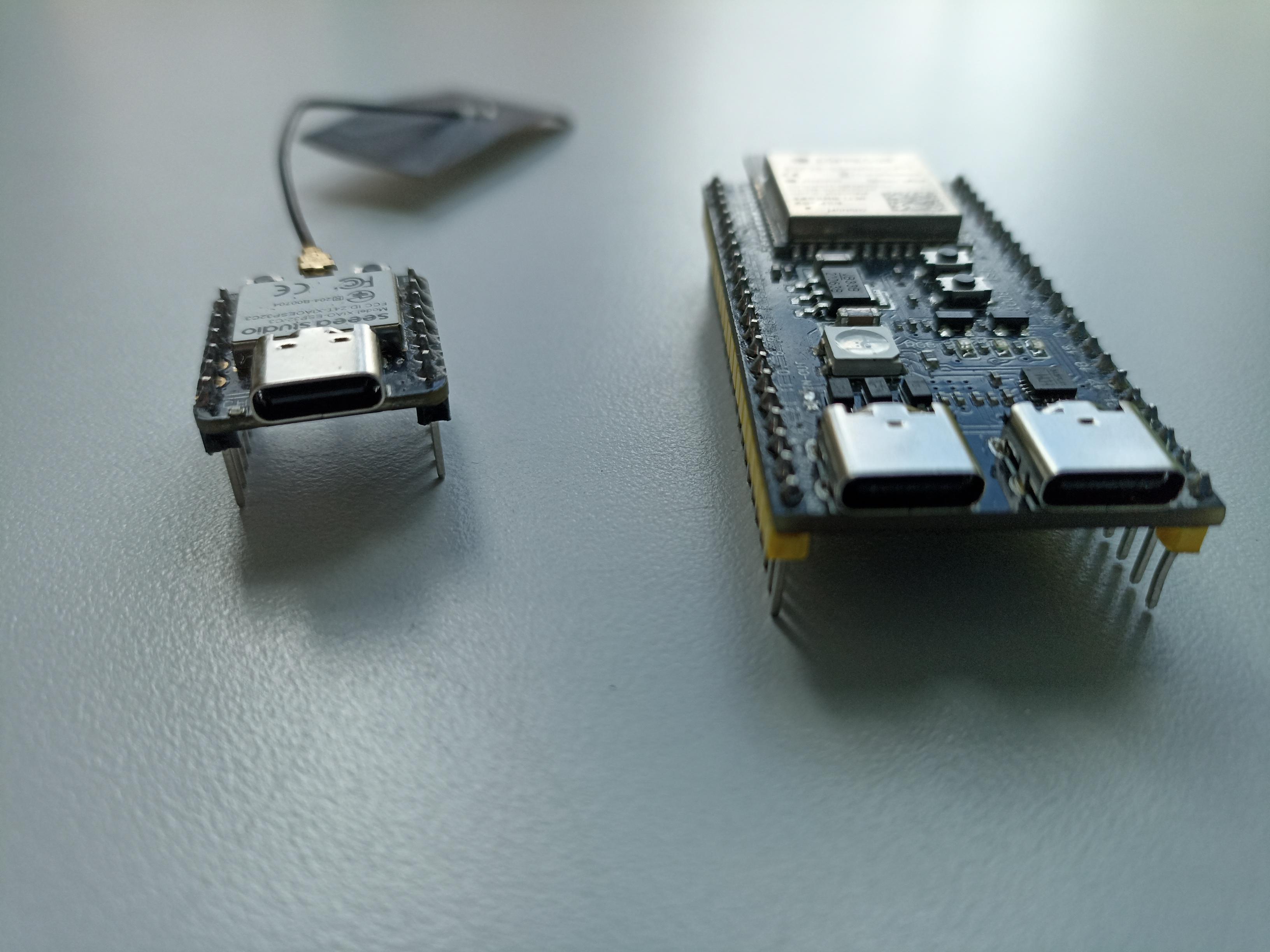
Real size comparison between XIAO ESP32-C3 and ESP32-S3 DevKitC-1
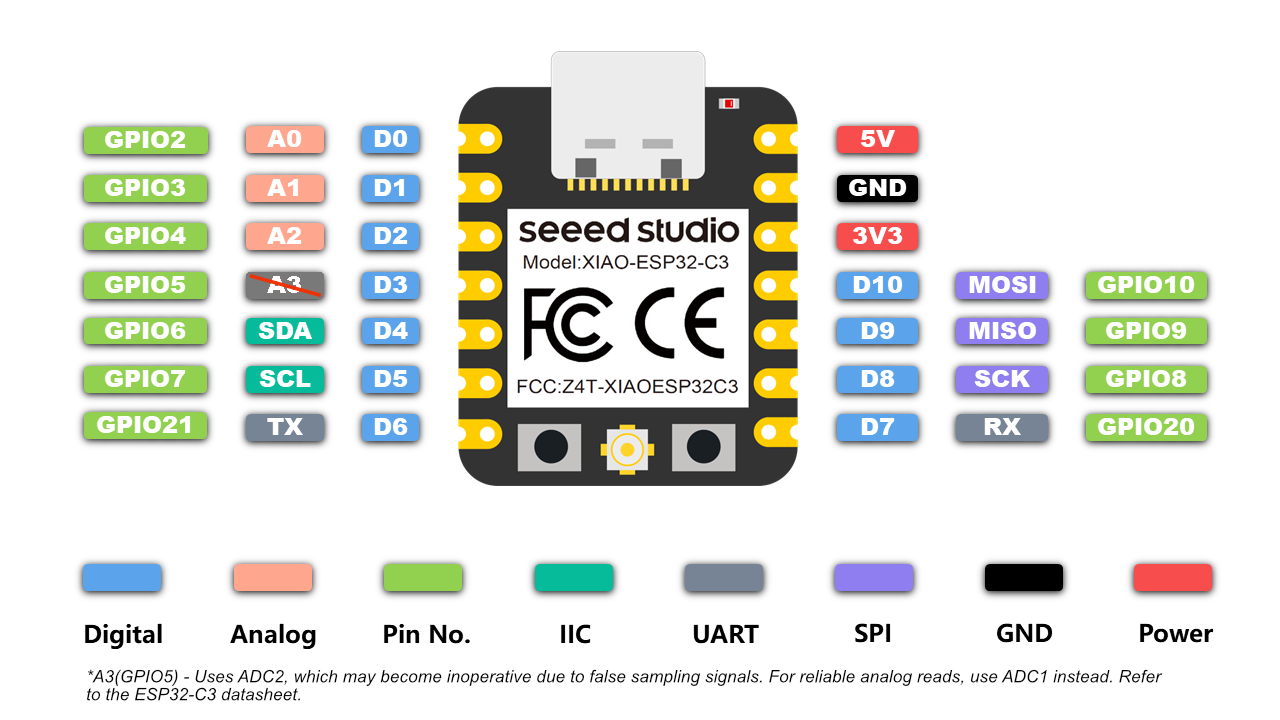
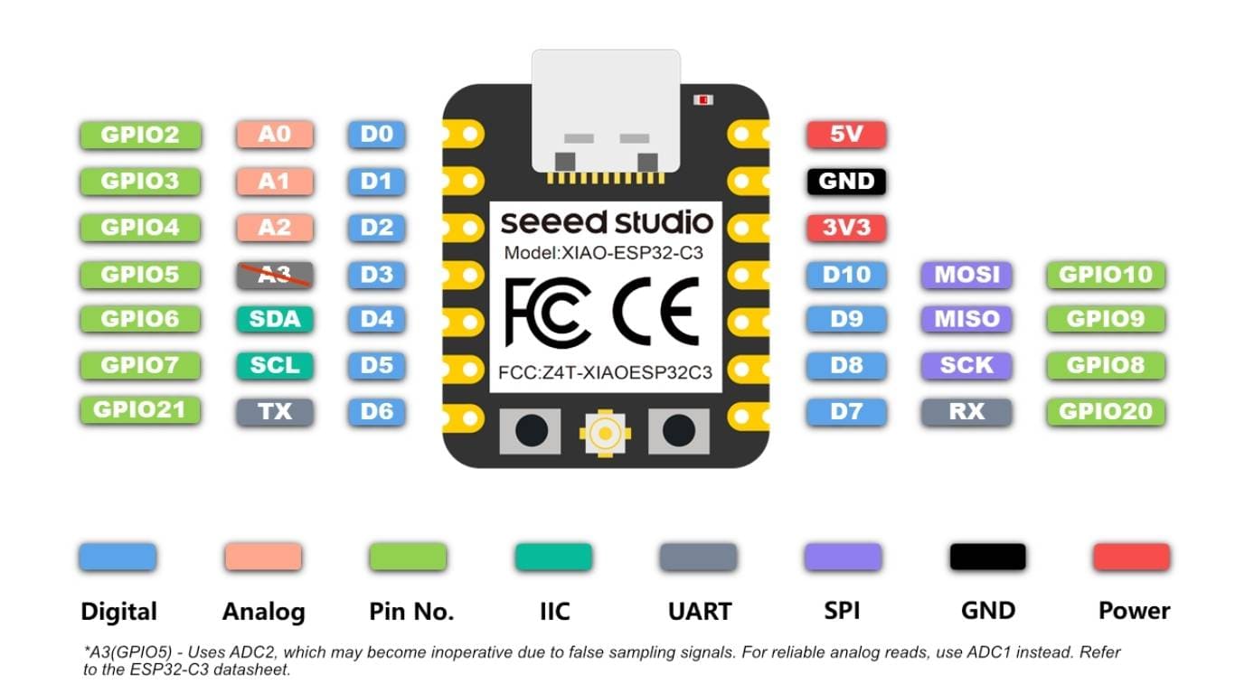
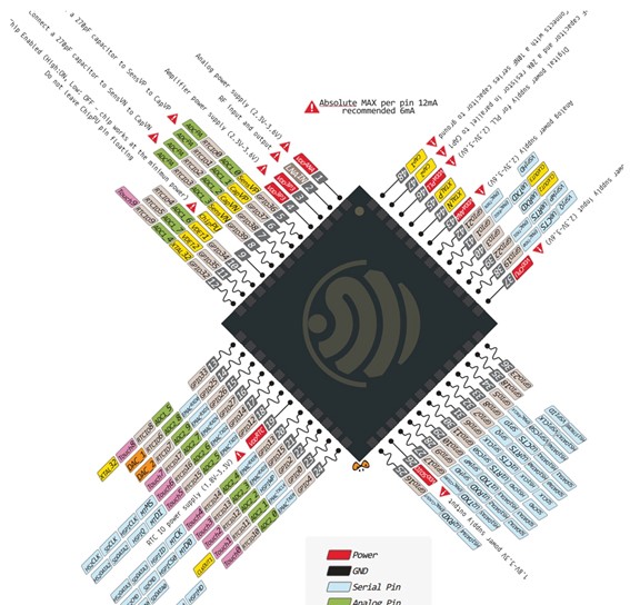
XIAO ESP32-C3 Pinout – compact layout with multifunction GPIOs
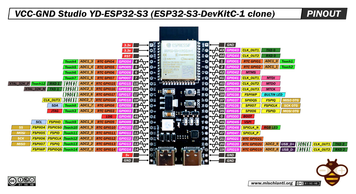
ESP32-S3 DevKitC-1 Pinout – detailed and expandable interface map
| Component | XIAO ESP32-C3 | ESP32-S3 DevKitC-1 |
|---|---|---|
| USB Port | USB Type C (modern, reversible) | USB Micro B (more common, less robust) |
| Supported Voltages | 3.3V and 5V | 3.3V and 5V |
| Physical Buttons | None (some have one programmable button) | Reset + Boot |
| Header Type | 2x7 side pins (only 11 GPIOs) | 2x19 pins with extensive labeling |
These microcontrollers are flexible and support multiple programming environments, depending on your preference or skill level:
For this assignment, Michael Sebastián Torres and Andrés Felipe Guarnizo worked together to explore and compare different embedded architectures using multiple development boards. Each board was configured and tested using its respective toolchain and programming environment.
The following table summarizes the environments and tools used for each board:
| Board | Architecture | Toolchain | IDE / Environment | Programming Language |
|---|---|---|---|---|
| Arduino UNO | AVR | Arduino Core for AVR | Arduino IDE | C/C++ |
| XIAO ESP32-C3 | ESP32 | ESP32 Arduino Core | Arduino IDE | C++ |
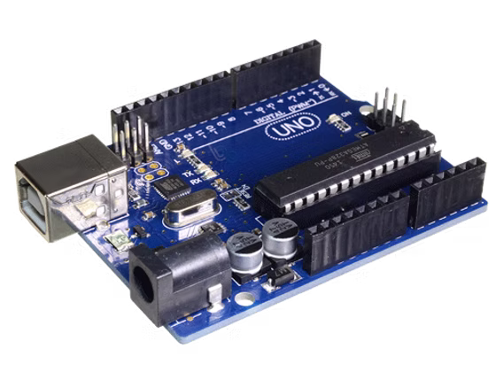
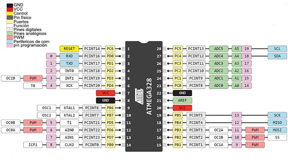
The Arduino UNO is perhaps one of the most iconic development boards in electronics and education. It uses the ATmega328P microcontroller and is known for its simplicity, robustness, and broad compatibility with sensors, actuators, and libraries. As a board, it's perfect for understanding basic embedded logic, digital and analog pin control, and serial communication. Its limitations in memory and processing power are balanced by its reliability and accessibility, which is why we selected it to contrast with more modern boards.
| Specification | Arduino UNO |
|---|---|
| Microcontroller | ATmega328P |
| Operating Voltage | 5V |
| Input Voltage (recommended) | 7-12V |
| Digital I/O Pins | 14 (6 PWM) |
| Analog Input Pins | 6 |
| Clock Speed | 16 MHz |
| Flash Memory | 32 KB |
| SRAM | 2 KB |
| EEPROM | 1 KB |
The XIAO ESP32-C3 is a much more compact and powerful board that brings together small size and wireless communication capabilities. It is based on the ESP32-C3 chip, which uses a RISC-V core and supports Wi-Fi and Bluetooth Low Energy (BLE). From the moment it is configured in the Arduino IDE, it offers a much more complex potential: access to web communication, higher memory, and modern protocols. We used it to explore how a board with more recent architecture integrates into the same workflow but opens up more advanced embedded systems possibilities.
| Specification | XIAO ESP32-C3 |
|---|---|
| Microcontroller | ESP32-C3 (RISC-V) |
| Operating Voltage | 3.3V |
| Wi-Fi | 802.11 b/g/n (2.4 GHz) |
| Bluetooth | Bluetooth 5.0 (LE) |
| Digital I/O Pins | 11 (4 PWM) |
| Analog Input Pins | 4 |
| Clock Speed | 160 MHz |
| Flash Memory | 4 MB |
| SRAM | 400 KB |
const int pinLDR = A0;
const int pinButton = 2;
const int pinRedLED = 9;
const int pinGreenLED = 10;
// Light threshold (adjust depending on environment)
const int lightThreshold = 300;
void setup() {
pinMode(pinButton, INPUT);
pinMode(pinRedLED, OUTPUT);
pinMode(pinGreenLED, OUTPUT);
Serial.begin(9600);
}
void loop() {
int lightValue = analogRead(pinLDR);
int buttonState = digitalRead(pinButton);
Serial.print("Light: ");
Serial.print(lightValue);
Serial.print(" | Button: ");
Serial.println(buttonState);
if (buttonState == HIGH) {
digitalWrite(pinRedLED, HIGH);
digitalWrite(pinGreenLED, LOW);
} else if (lightValue < lightThreshold) {
digitalWrite(pinRedLED, LOW);
digitalWrite(pinGreenLED, HIGH);
} else {
digitalWrite(pinRedLED, LOW);
digitalWrite(pinGreenLED, LOW);
}
delay(100);
}
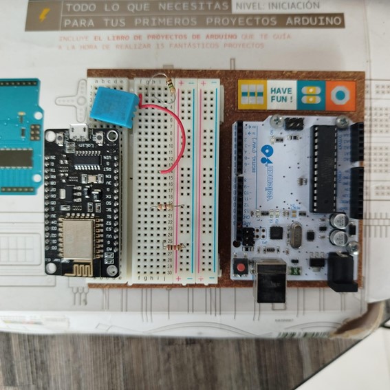
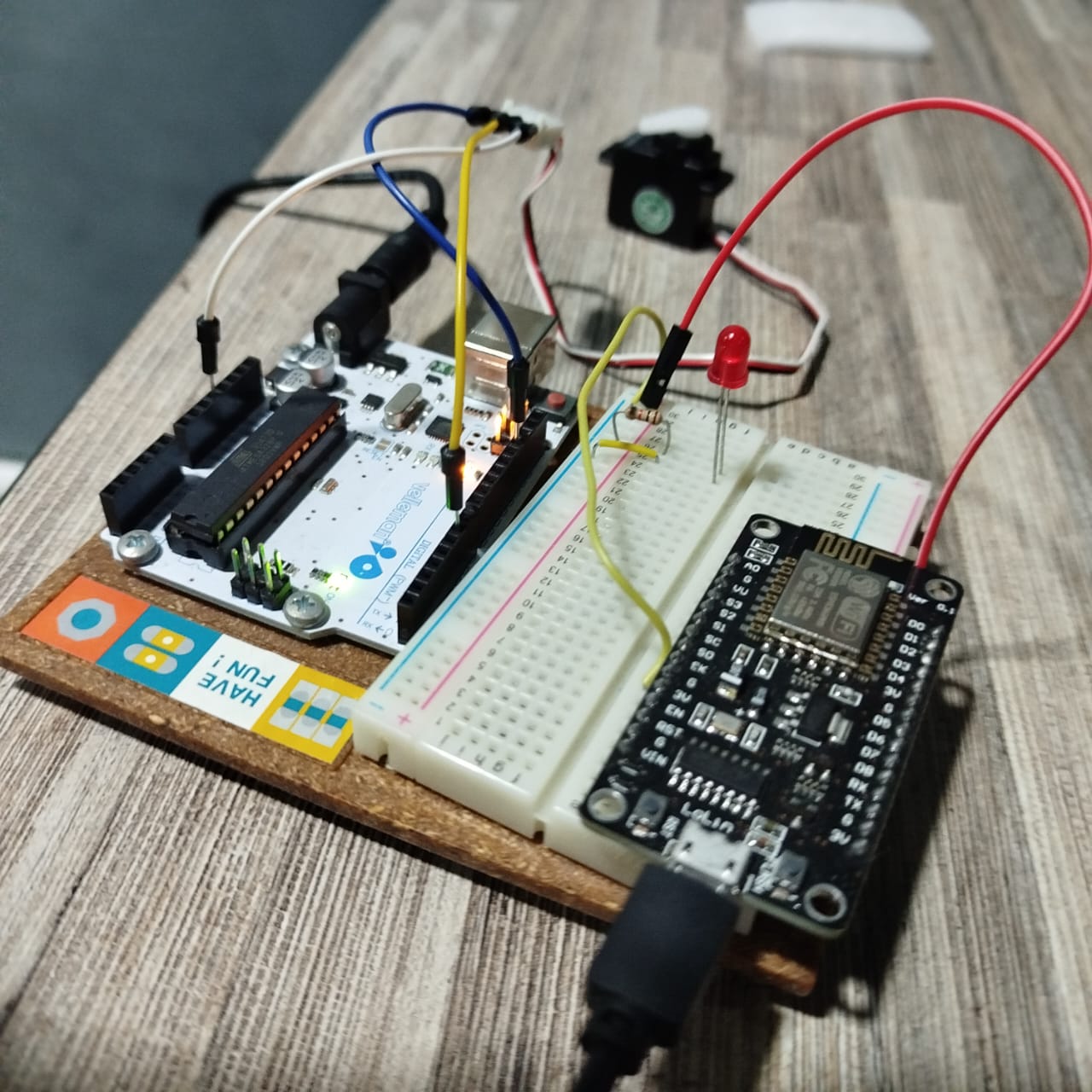
}Here you can see the system in action.
https://raw.githubusercontent.com/espressif/arduino-esp32/gh-pages/package_esp32_index.json
const int buttonPin = 2;
const int redLedPin = 9;
const int greenLedPin = 10;
const int ldrPin = A0;
void setup() {
pinMode(buttonPin, INPUT);
pinMode(redLedPin, OUTPUT);
pinMode(greenLedPin, OUTPUT);
Serial.begin(9600);
}
void loop() {
int buttonState = digitalRead(buttonPin);
int ldrValue = analogRead(ldrPin);
if (buttonState == HIGH) {
digitalWrite(redLedPin, HIGH);
digitalWrite(greenLedPin, LOW);
} else if (ldrValue < 500) {
digitalWrite(redLedPin, LOW);
digitalWrite(greenLedPin, HIGH);
} else {
digitalWrite(redLedPin, LOW);
digitalWrite(greenLedPin, LOW);
}
delay(100);
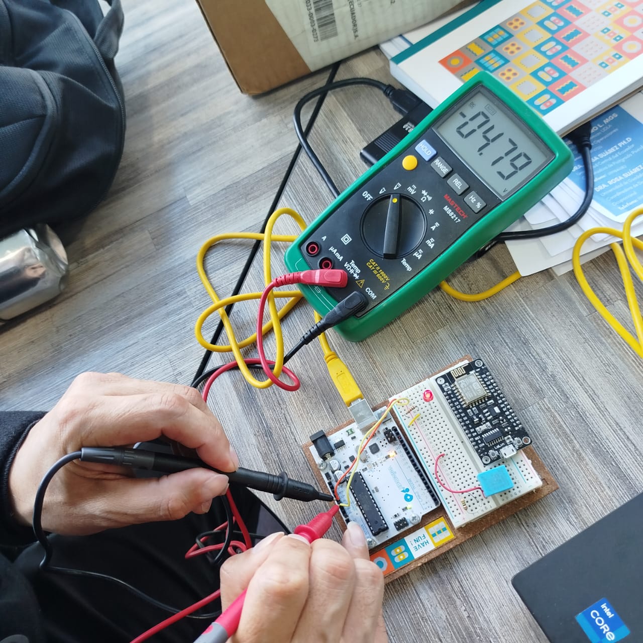
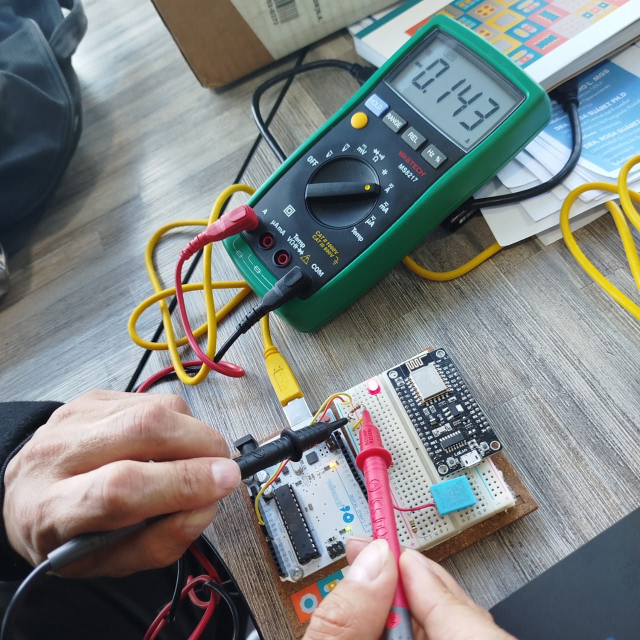
}Here you can see the XIAO ESP32 C3 in action.
| Feature | Arduino Uno | ESP32-C3 |
|---|---|---|
| Architecture | AVR (8-bit) | RISC-V (32-bit) |
| Clock Speed | 16 MHz | 160 MHz |
| Flash Memory | 32 KB | 400 KB + external |
| SRAM | 2 KB | 400 KB |
| GPIO Pins | 14 | 22 |
| Connectivity | None | Wi-Fi, BLE |
| USB Support | USB 2.0 | USB 2.0 |
Team: Manuel Ayala-Chauvin, Sandra Nuñez-Torres
Institution: Fablab - Universidad Tecnológica Indoamérica
Year: 2025
This comparative project explores the key specifications, connectivity features, and performance differences between Arduino Uno and ESP32-CAM. It includes pinout analysis, practical implementation, and performance tests to help beginners and makers understand how to choose the right board for a project.
| Feature | Arduino Uno | ESP32-CAM |
|---|---|---|
| Microcontroller | ATmega328P | Tensilica Xtensa LX6 |
| Clock Speed | 16 MHz | 160–240 MHz |
| WiFi Connectivity | No | Yes |
| Camera Support | No | Yes (2MP OV2640) |
| Price | $12.00 | $17.00 |
This experiment involved LED blinking with Arduino Uno and image streaming with ESP32-CAM to illustrate typical use cases.
void setup() {
  pinMode(13, OUTPUT);
}
void loop() {
  digitalWrite(13, HIGH);
  delay(1000);
  digitalWrite(13, LOW);
  delay(1000);
}
Upload the CameraWebServer example from the Arduino IDE (ESP32 board package must be
installed). Set WiFi credentials in the sketch before uploading. Use GPIO 0
grounded during flashing.
While Arduino Uno is excellent for simple embedded projects, ESP32-CAM is more powerful and ideal for IoT and computer vision tasks. This experiment highlights their differences in use case, connectivity, and real-world performance.