
To begin with laser machine safety, it is essential to have knowledge of the space in which it is located. This will allow us to first have a general overview and then focus on the specific details.
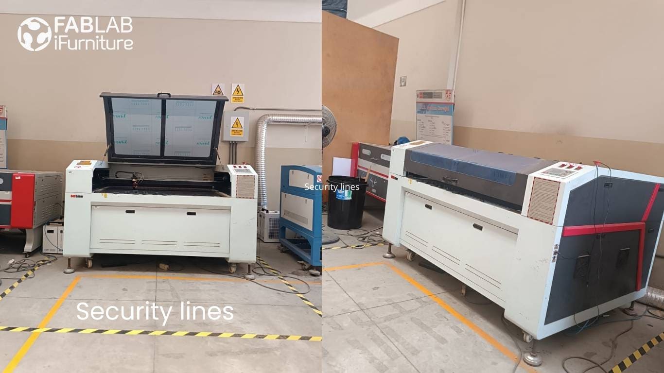
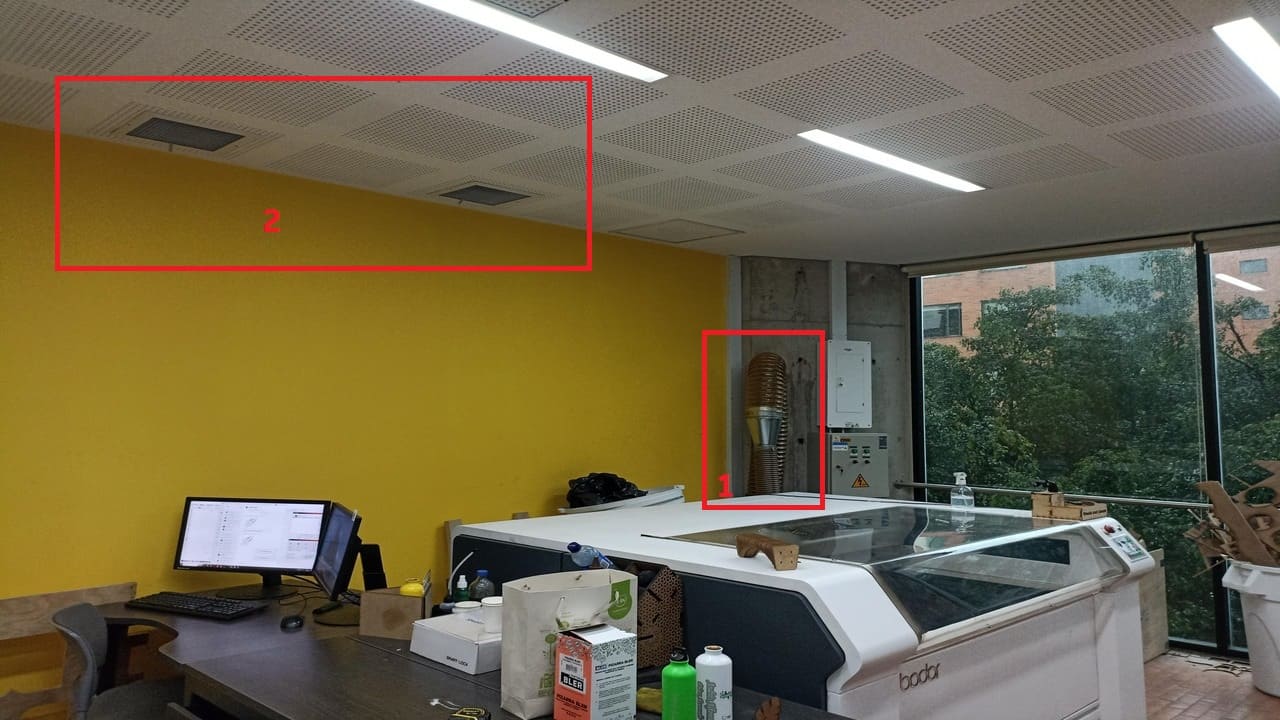
In the Fab Lab iFurniture, you can see a safety area around the CNC laser machine, marked by yellow lines with black stripes, which are visibly marked on the floor. This is to prevent people from entering the work area without the proper protection.
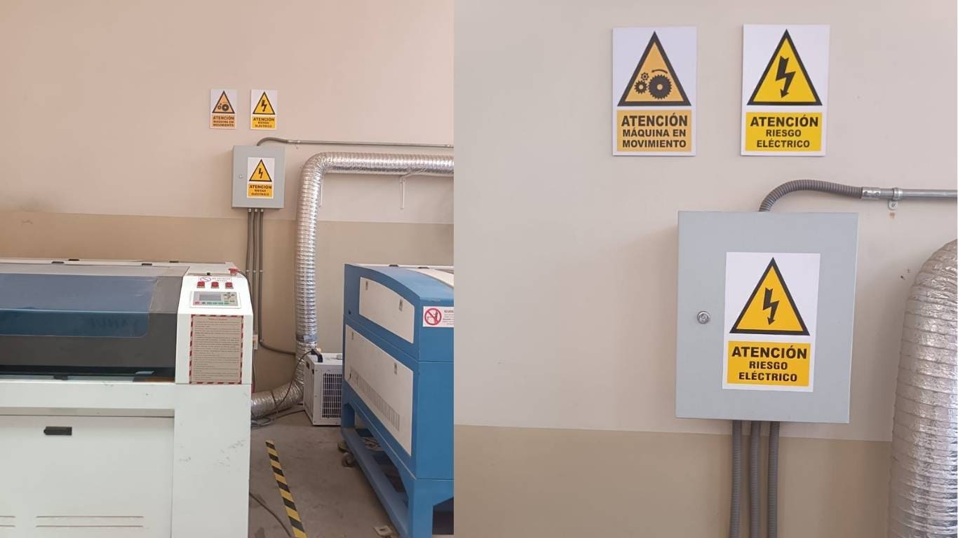
It is essential to have proper signage in the workspace. The signs should be visible and clear to warn about laser hazards, electrical risks, and safety rules to follow. Additionally, the signage helps maintain order in the workspace and preserve the condition of the machine.
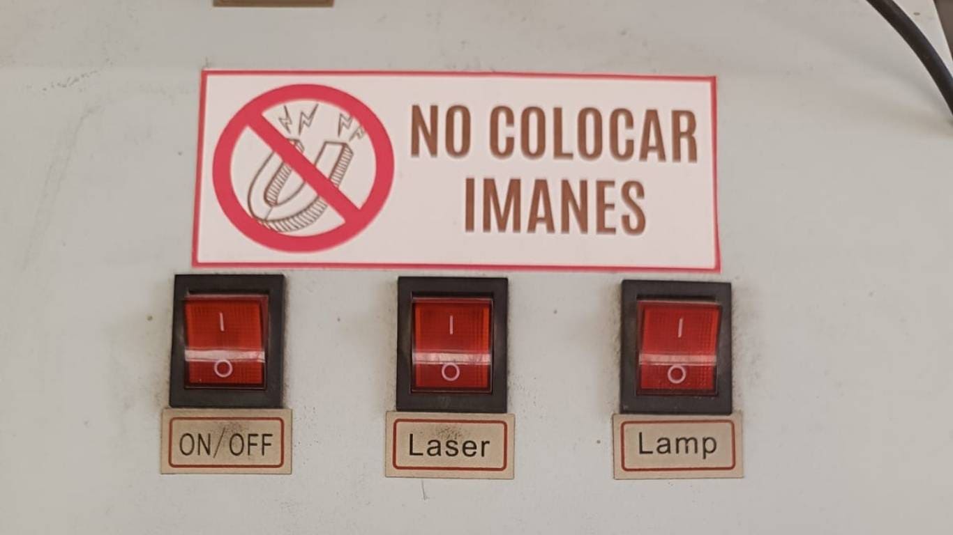
Signage also helps preserve the machine. For instance, in the area where the laser controls are located, it is forbidden to place magnets, as this could damage the equipment.
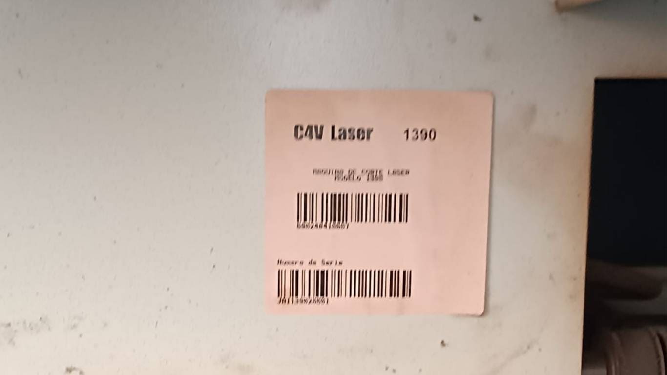
One of the things we must know before operating the machine is the type of equipment we are using. The machine in the Fab Lab iFurniture is of Chinese origin, a C4V laser 1390 type.
The CNC laser machine also has a stabilizer that powers on the entire machine. It also has ports to connect to the internet, the computer, or directly via USB. It includes the power buttons for the machine, the laser, and the lamp.
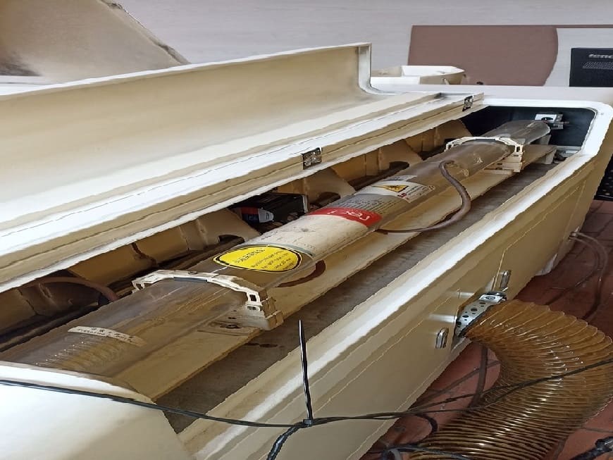
A laser tube in a laser machine is the main component that generates the laser beam. Its function is to convert electrical energy into concentrated laser light, which is used to cut, engrave, or mark materials with precision. The power and type of the laser tube determine which materials the machine can process and the quality of the results.
First, before starting the activity, I check what materials are available in the Ifurniture Fab Lab and choose the one that will best help me develop the project.
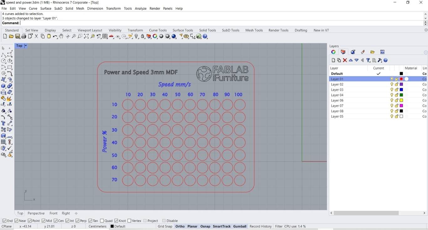
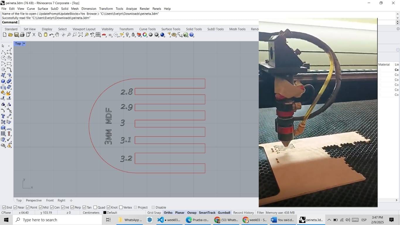
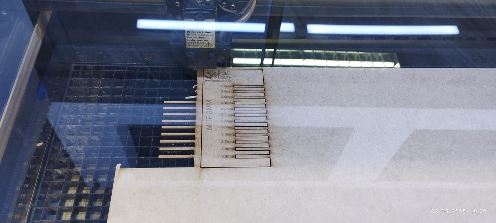
Once the material is selected, I design the template in the Rhinoceros program, where I will conduct the power and speed test using 3mm MDF.
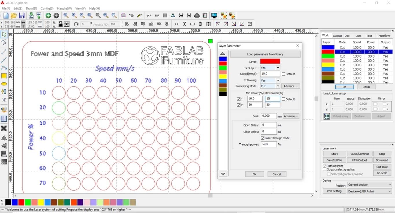
The software compatible with the machine that I used is RDWorks, which will assist me in the testing.
I configure the colors, assigning each one a specific power and speed. I start with a speed of 10 and increase it to 100, while adjusting the power from 10 to 70.
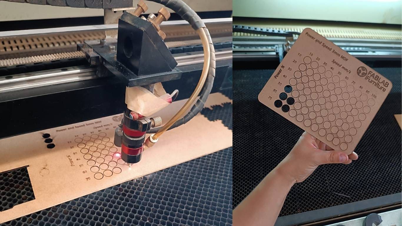
An important step before working with the machine is knowing the material thickness, in order to make the necessary configurations and calibrations.
The C4V Laser 1390 is a high-precision laser cutting and engraving machine. It features a working size of 1300x900 mm, allowing for the processing of large materials. It is ideal for cutting and engraving a variety of materials such as wood, acrylic, leather, and more. Additionally, it has an efficient control system and is compatible with various software to facilitate its use.
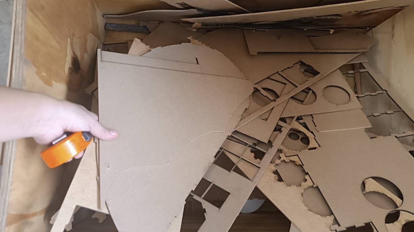
For the assignment of characterizing the focus, power, speed, and acceleration of the laser cutter, we selected a material from the Re-trazos project of the Fab Lab iFurniture, aiming to recycle it and use it in our test.
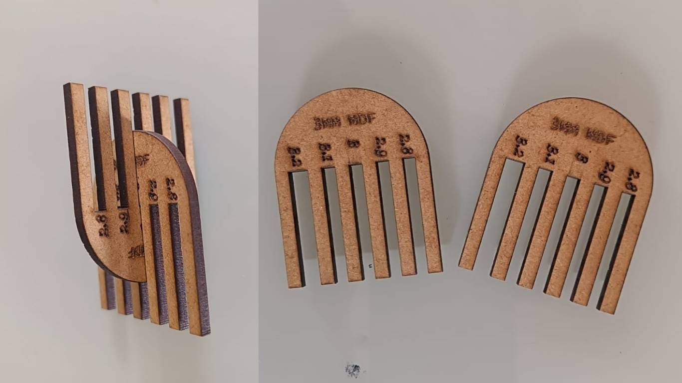
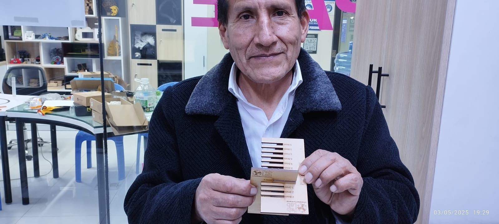
This is the result of the comb, which ranges from 2.8 mm to 3.2 mm. With a tolerance of 2.8 mm, it didn't fit, but at 3 mm, it fit precisely. With values of 3.1 mm and 3.2 mm, it fit without any difficulty.
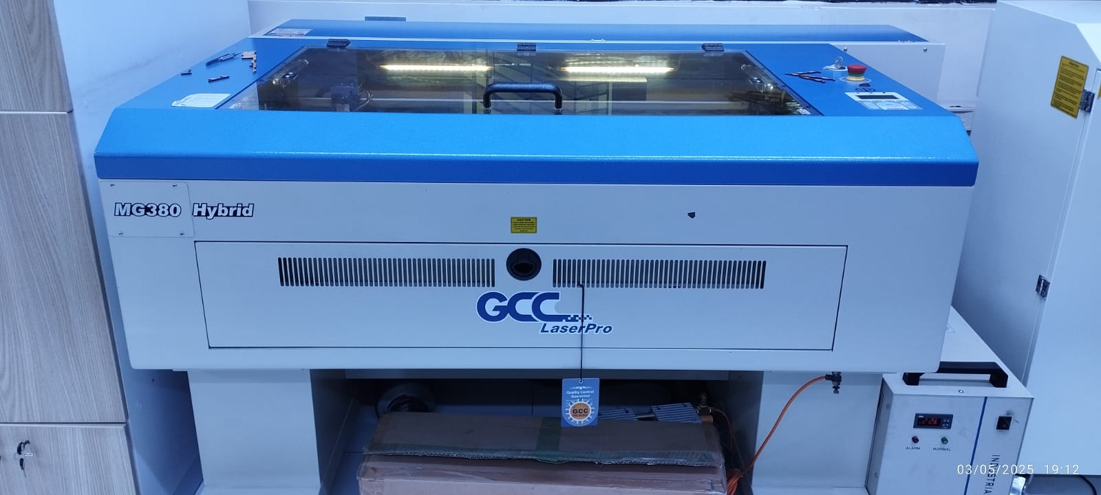
The MG380 Hybrid is a hybrid technology laser cutting and engraving machine developed by GCC LaserPro, which combines two laser sources in a single unit: a radio frequency (RF)-driven metal laser tube for high-precision engravings, and a high-power CO₂ glass laser tube for efficient cutting in thick materials. This configuration allows for both detailed engravings and deep cuts in a wide variety of materials, including wood, acrylic, leather, paper, and textiles.
To develop this work, I visited the Continental University Fab Lab in Huancayo, where I was provided with the use of the machines. The machines are located in a safe and signposted area, and also have personal safety equipment.
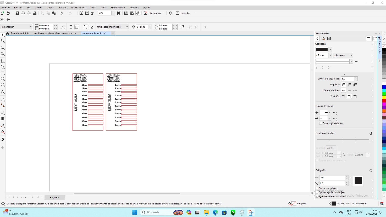
o perform this test, a comb was designed with specific cuts of various dimensions according to the following details: 2.8 mm, 2.9 mm, 3.0 mm, 3.2 mm, 3.4 mm, 3.6 mm and 3.8 mm.
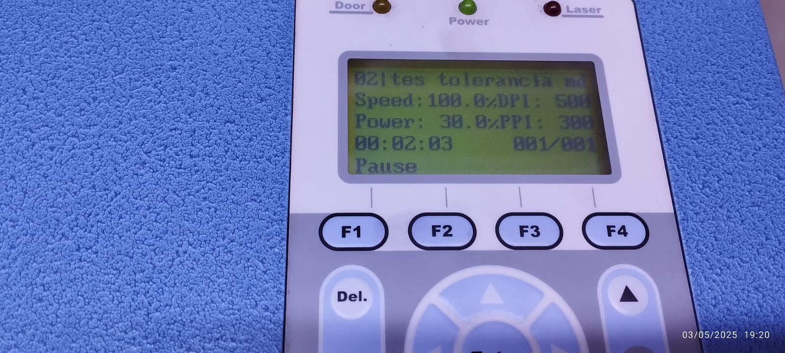
After sending a file to the cutter for cutting, the name of the imported file will appear on the cutter screen with the cutting characteristics. It is important to check that these are the same as those configured on the computer before sending them.
The reason for checking a variety of dimensions is the need to find the most precise and effective fit between the two dies. Understanding how these parts interact in terms of coupling is essential for an ideal combination of power, speed, and frequency to avoid burns, melted edges, or incomplete cuts. This way, we maximize performance and utility when performing our future jobs.
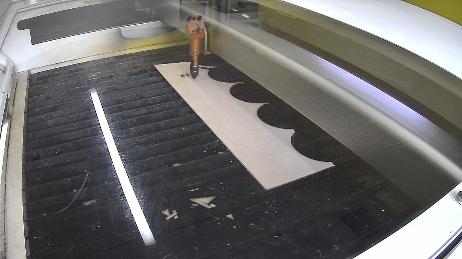
cutting process
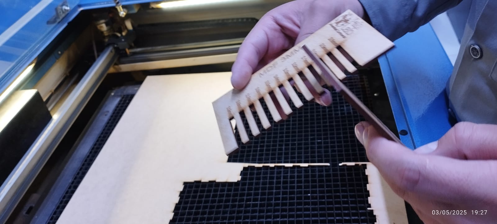
We can notice the difference once the combs are cut.
During the task, I understood the importance of meticulously calibrating the laser machine, precisely adjusting the speed and power parameters to optimize both cutting efficiency and precision. All of this was done to ensure high cutting accuracy and a quality result.
1)Laser Cutter Safety Training EAN lAb At the FabLab of Universidad EAN, a series of safety measures have been implemented to ensure the proper and safe use of the 150W laser cutter. These measures include:
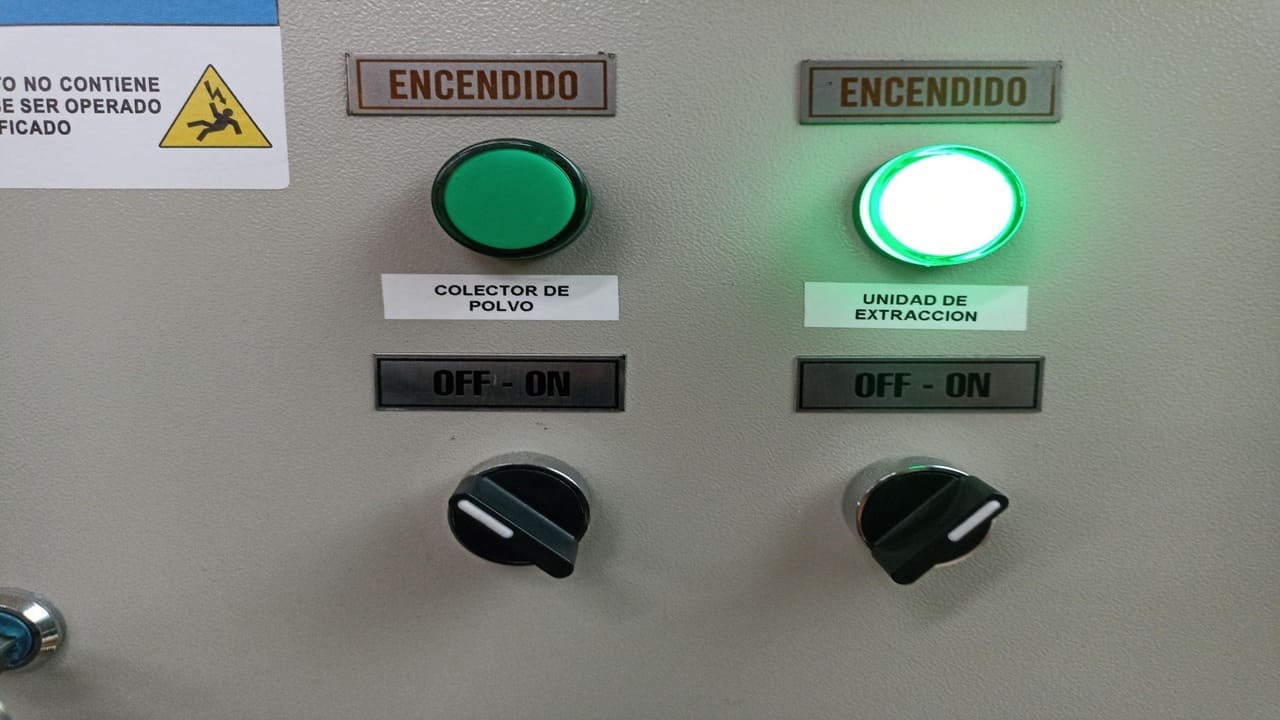
1.1) Ventilation and Air Extraction: 
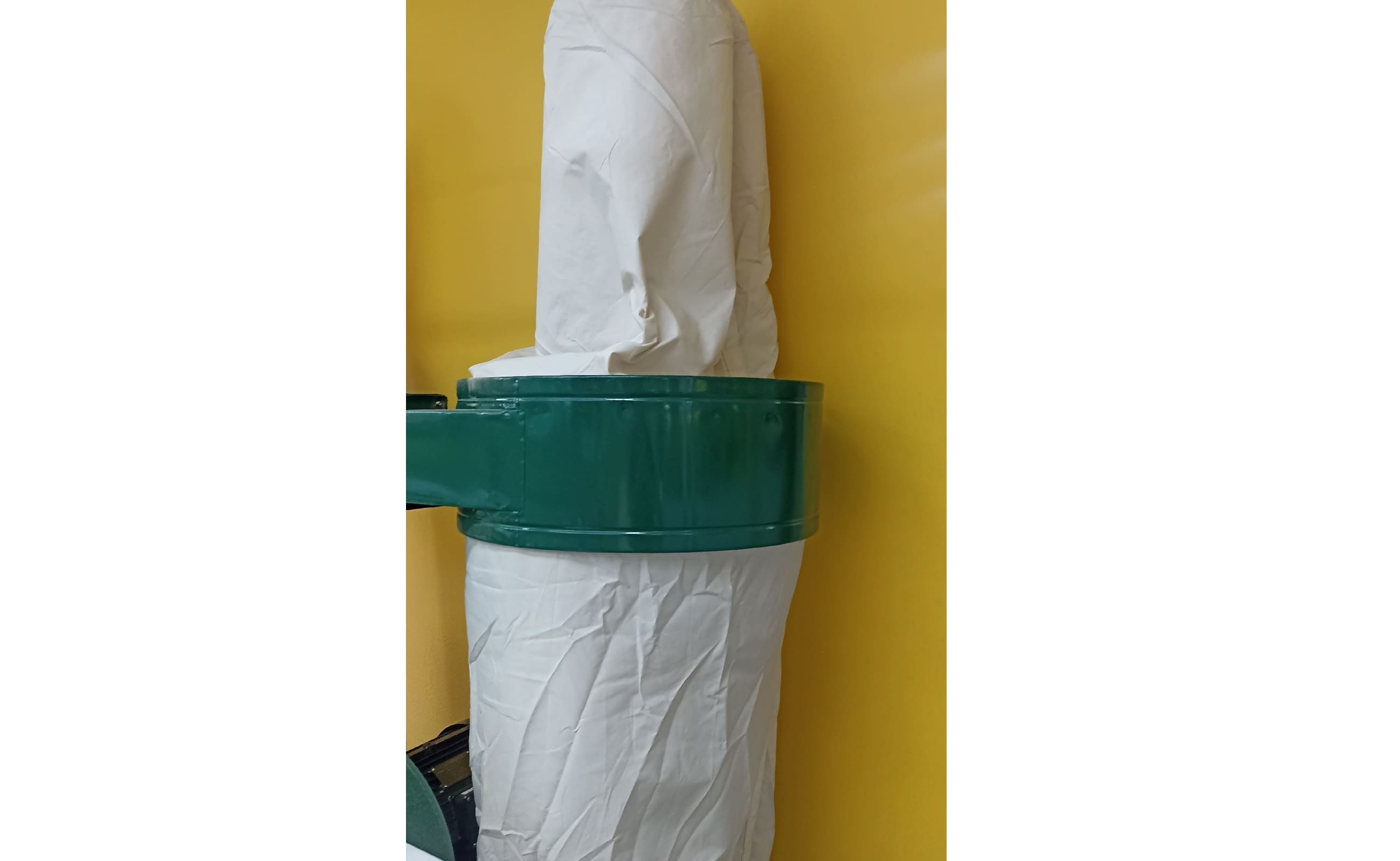
The machine is equipped with a cooling system (chiller) to maintain the appropriate temperature during the cutting process. Additionally, a dust collector extractor has been installed to capture the particles and fumes generated during cutting. Furthermore, there is a room extractor to ensure adequate ventilation and prevent the accumulation of gases or toxic fumes.
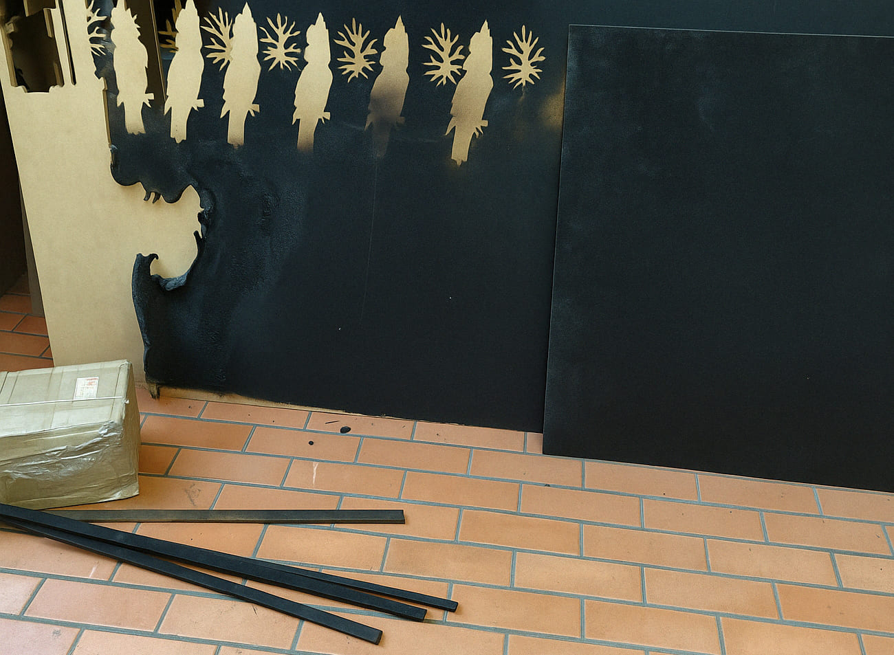
1.2) Prohibited Materials: 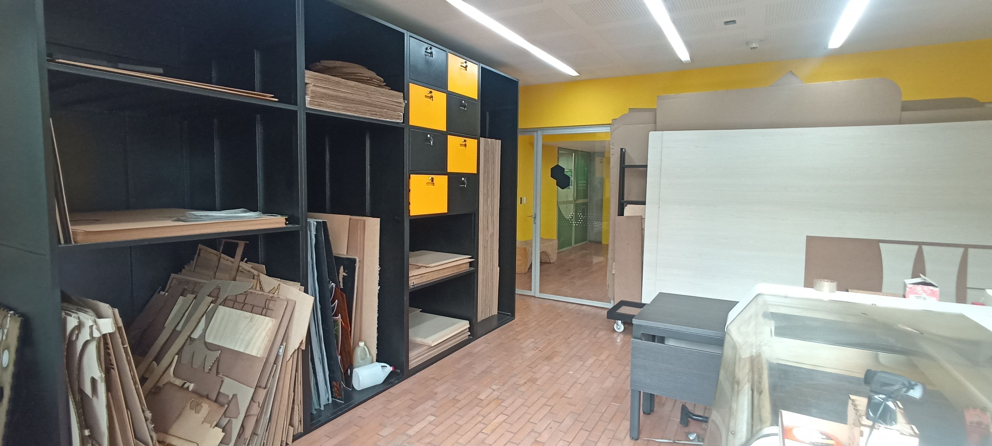
A clear list of materials that should not be processed in the laser cutter has been established, such as PVC, polycarbonate, and other materials that release toxic gases when cut. The use of metallic, reflective materials, or materials that may generate sparks is also prohibited.
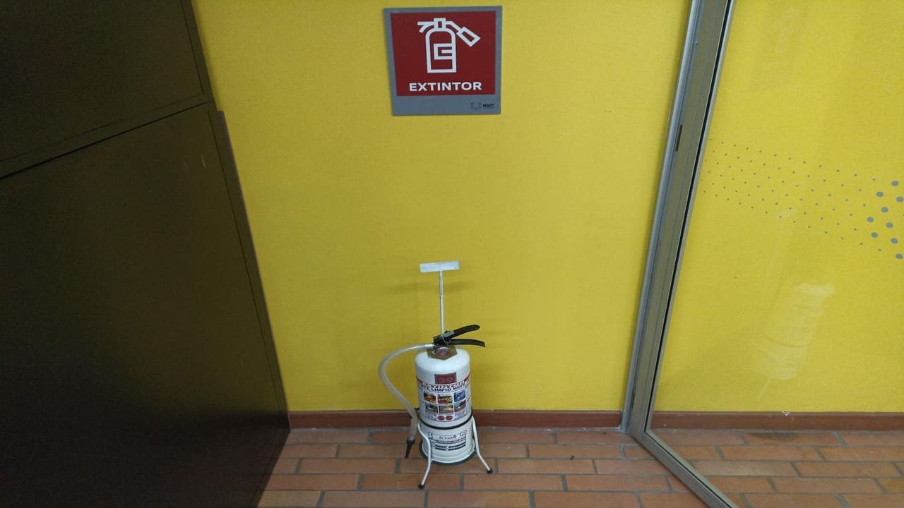
1.3) Fire Prevention 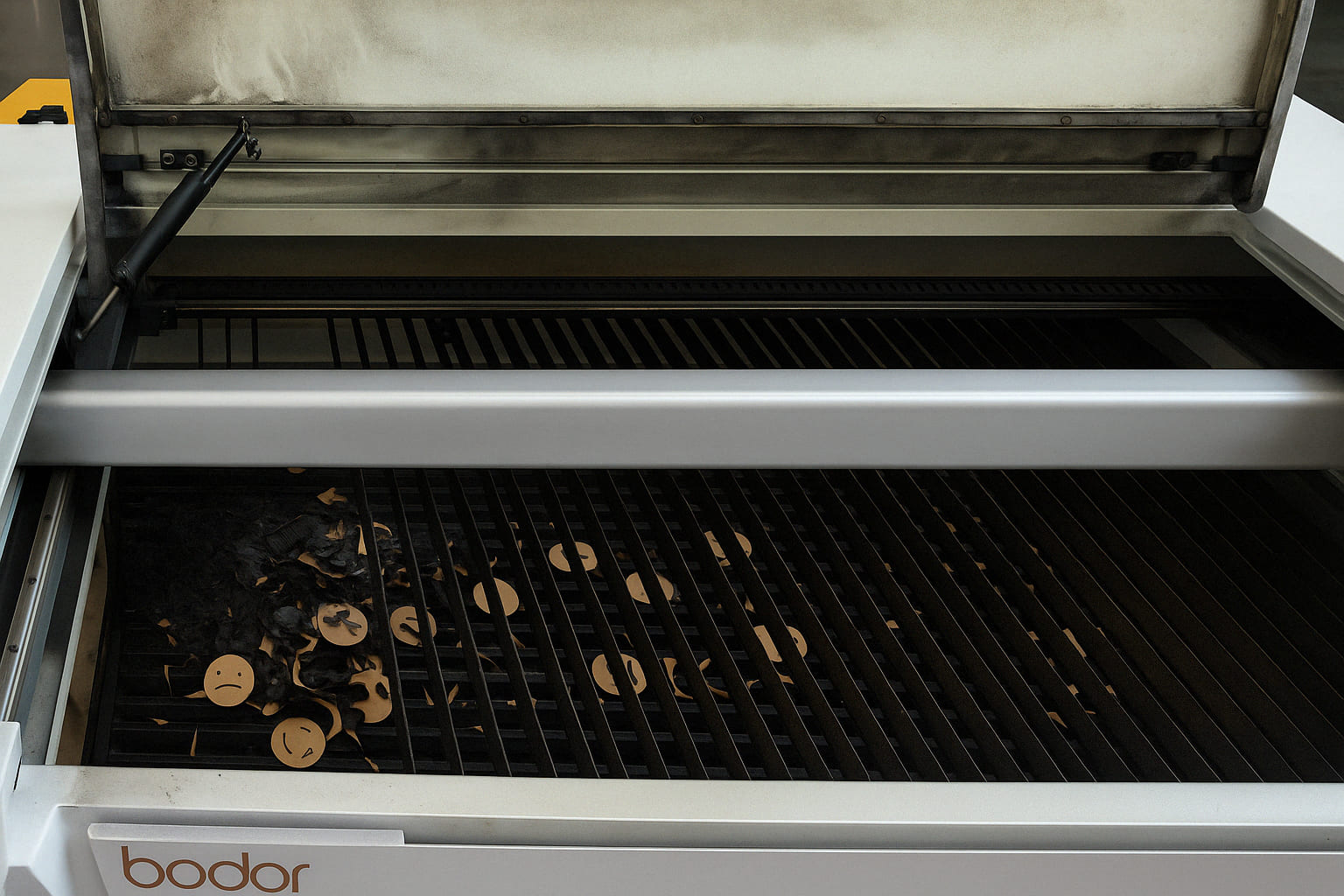
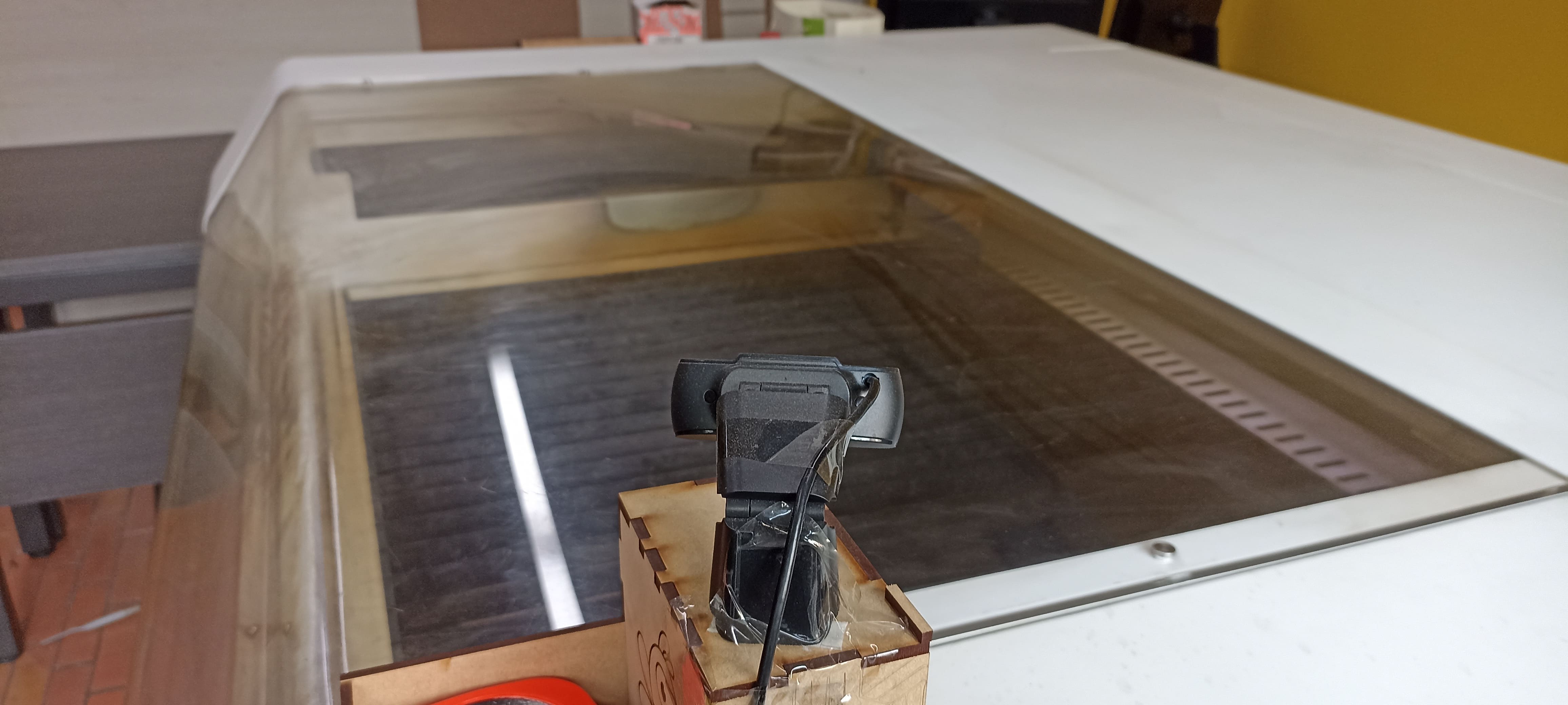
Due to an incident that occurred a year ago, in which a material caught fire during the cutting process, safety measures have been reinforced. A fire extinguisher has been placed near the machine to act quickly in case of an emergency. In addition, a surveillance camera has been installed, allowing for remote and real-time monitoring of the laser cutter, which helps us detect any anomalies or fire risks immediately.
1.4) Training and Key Guidelines: All users of the laser cutter must complete a safety training before operating the machine. This training includes:
Understanding the ventilation rules and proper use of the extractors.
Identifying materials and their associated risks.
Learning how to use the fire extinguisher and follow fire protocols.
Constantly supervising the cutting process, either in person or through the surveillance camera.
2)Characterizing the Laser Cutter Parameters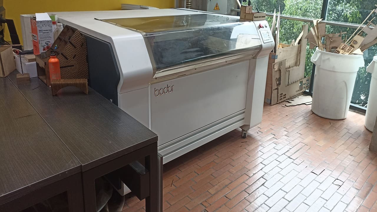
Before starting to operate in the laboratory, the FabLab team performs a brief calibration or verification of the mirrors to reduce variations in the width of the cut. This step is crucial, as it ensures the laser is properly aligned and that the cut is precise.
During this week, the group members designed our own cutting, power, and engraving tests to make an accurate comparison. We also conducted fit tests to determine the necessary clearances in the materials.
This machine has a laser that was recently replaced. It has 140 W of power, allowing it to cut multiple materials: wood, leather, fabric, etc. Many soft materials, but no metals.
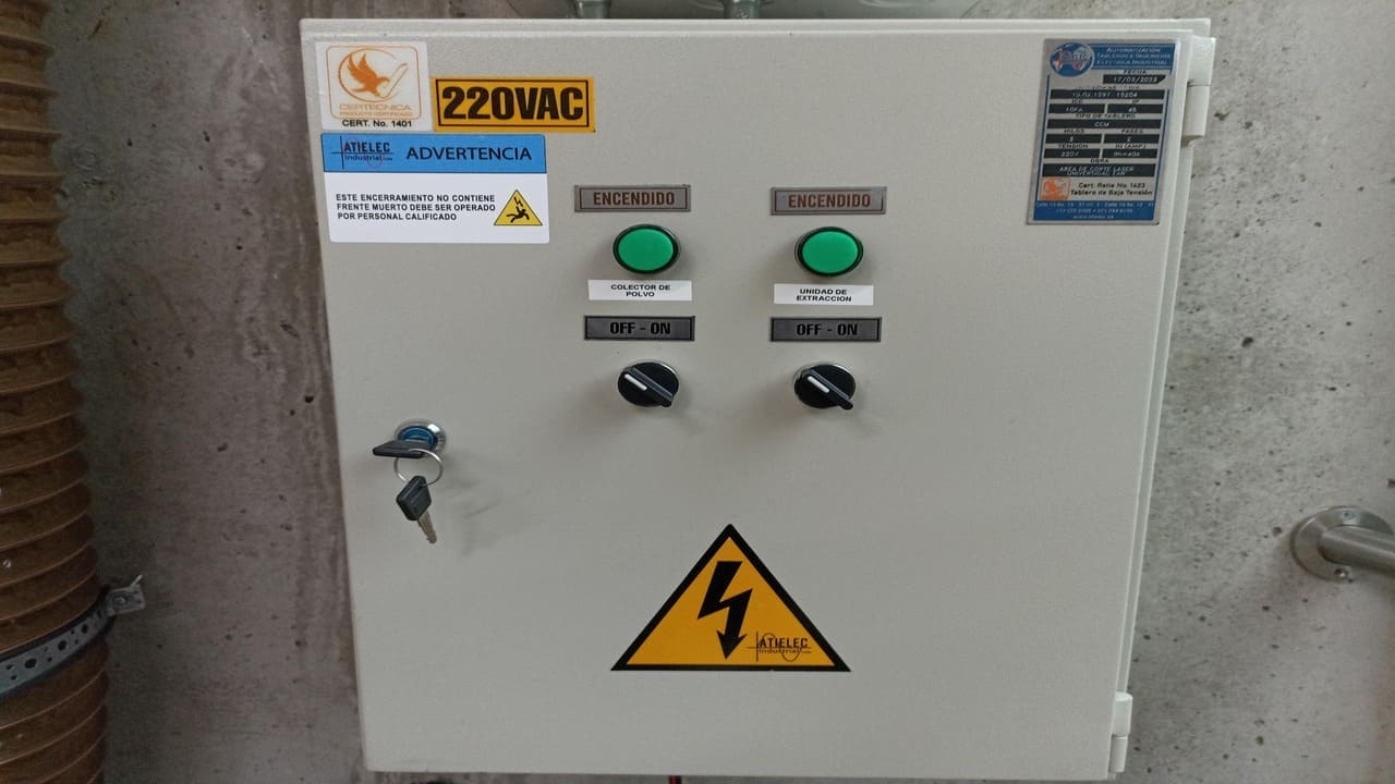
Moving on to the steps for working safely, we must first turn on the ventilation systems in the space: the room extractor, which removes odors that the direct extractor from the cutter might miss, and the design extractor, which turns on when the machine is operating.
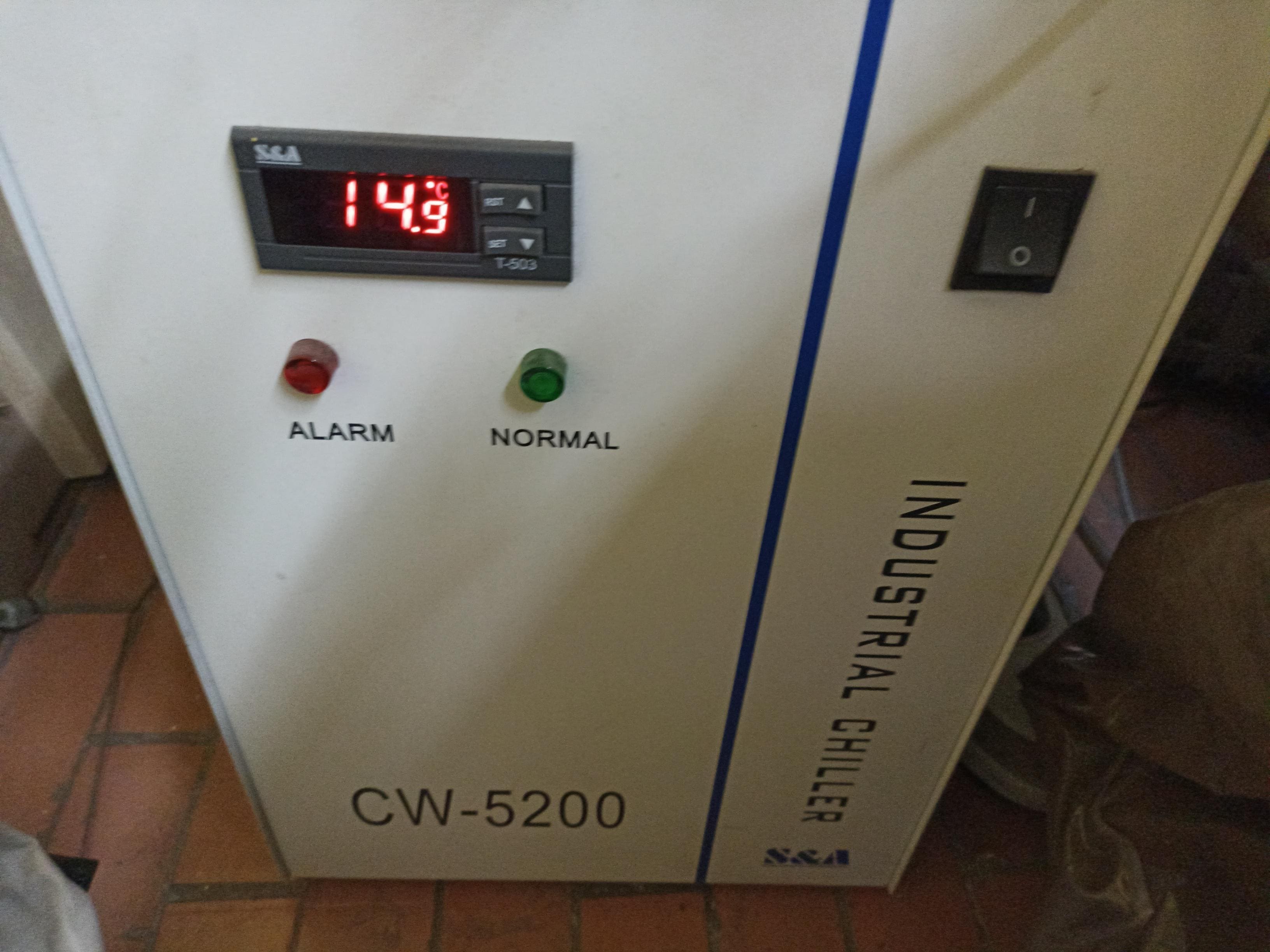
When turning on the machine, we check that the cooling water is circulating properly to prevent overheating and potential accidents.
Jhonatan Cortés’ contribution to this assignment is as follows: initially, I have always taken it as good practice to perform the laser validation and calibration to achieve the best results.
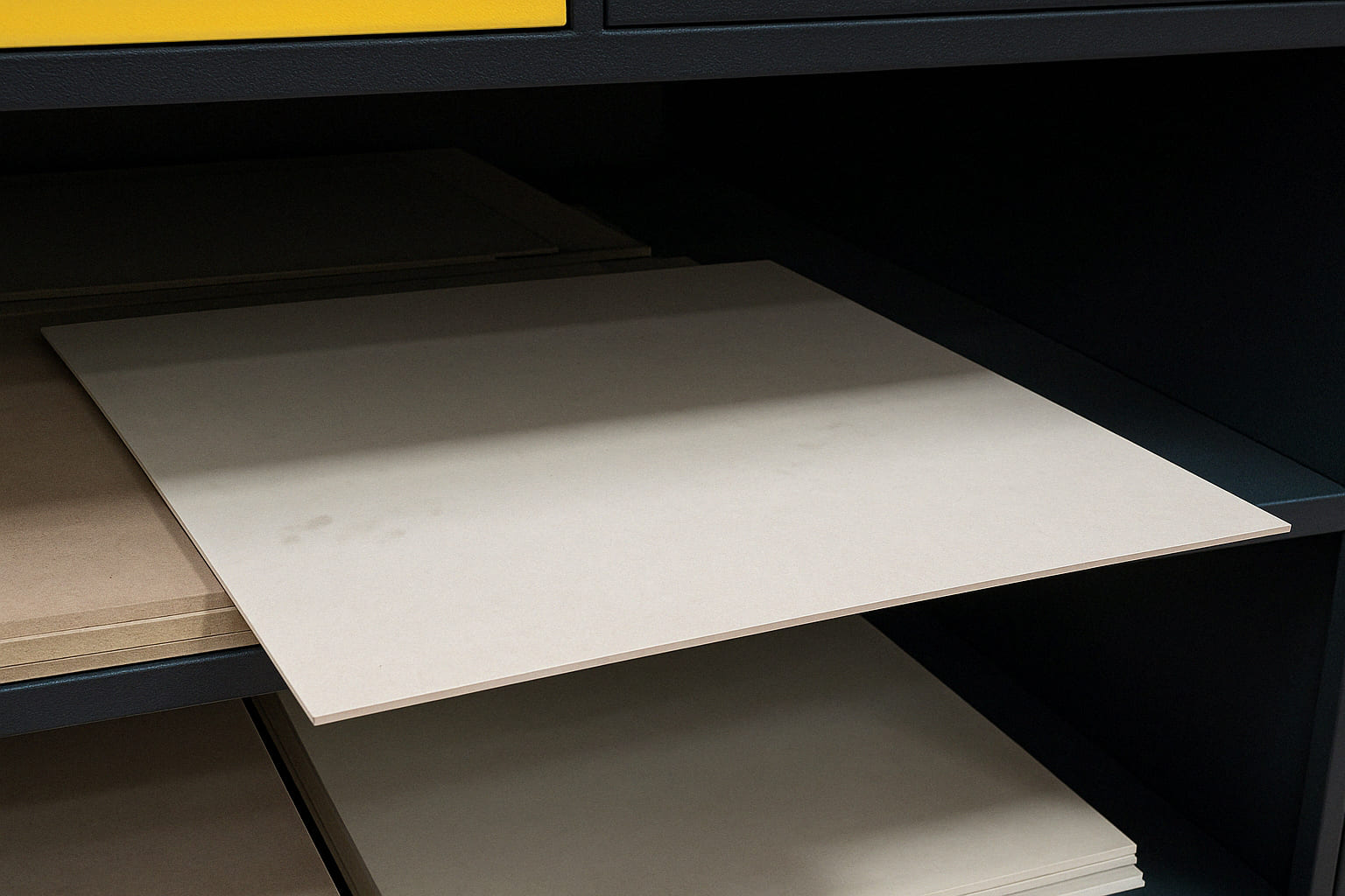
The material I chose to work with and test was 4 mm MDF. In this case, we previously prepared several 80 cm x 80 cm segments.
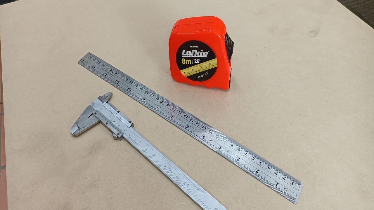
The tools required to work comfortably are usually these three: a tape measure, a ruler, and a caliper.
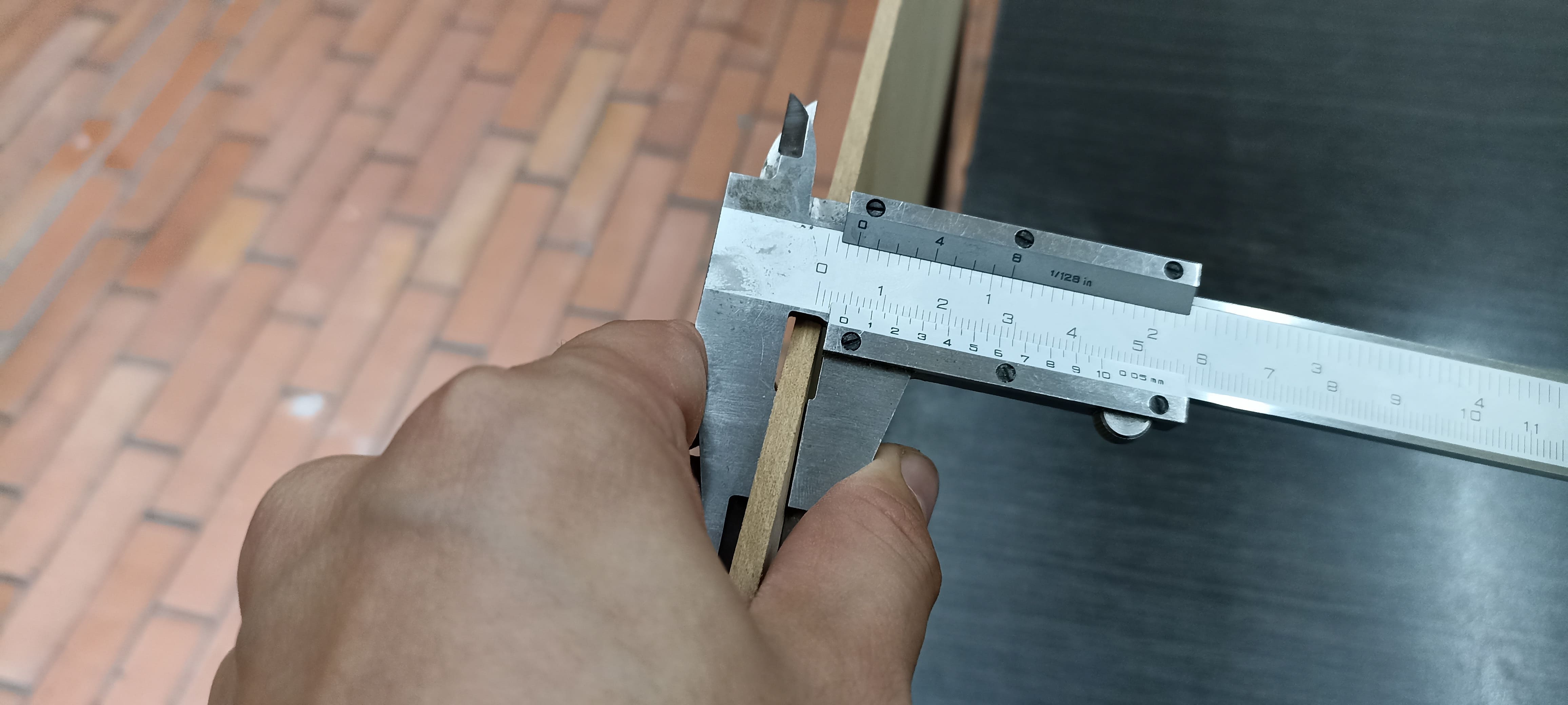
I used the caliper to verify the correct diameter of the material before mounting it.
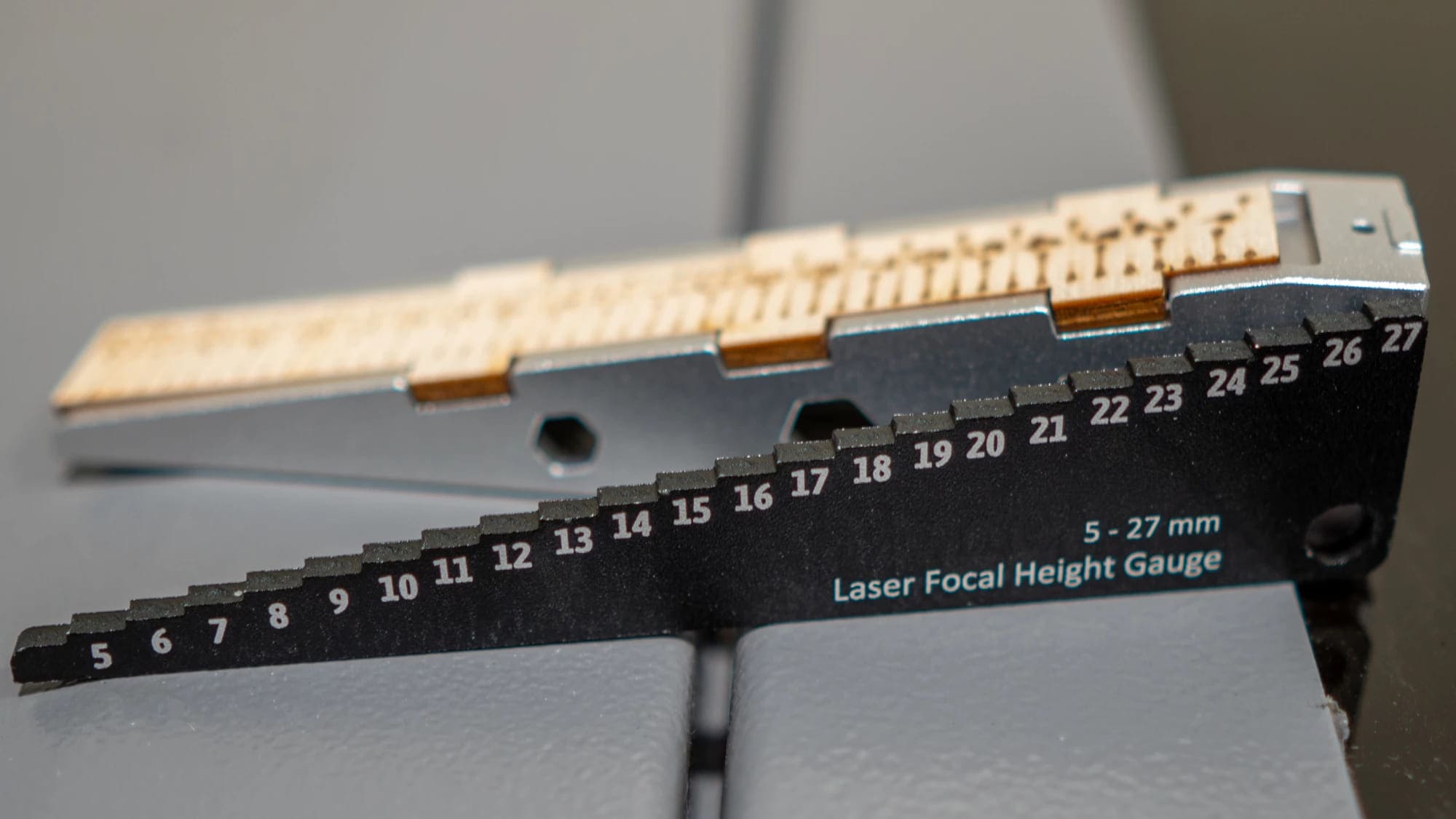
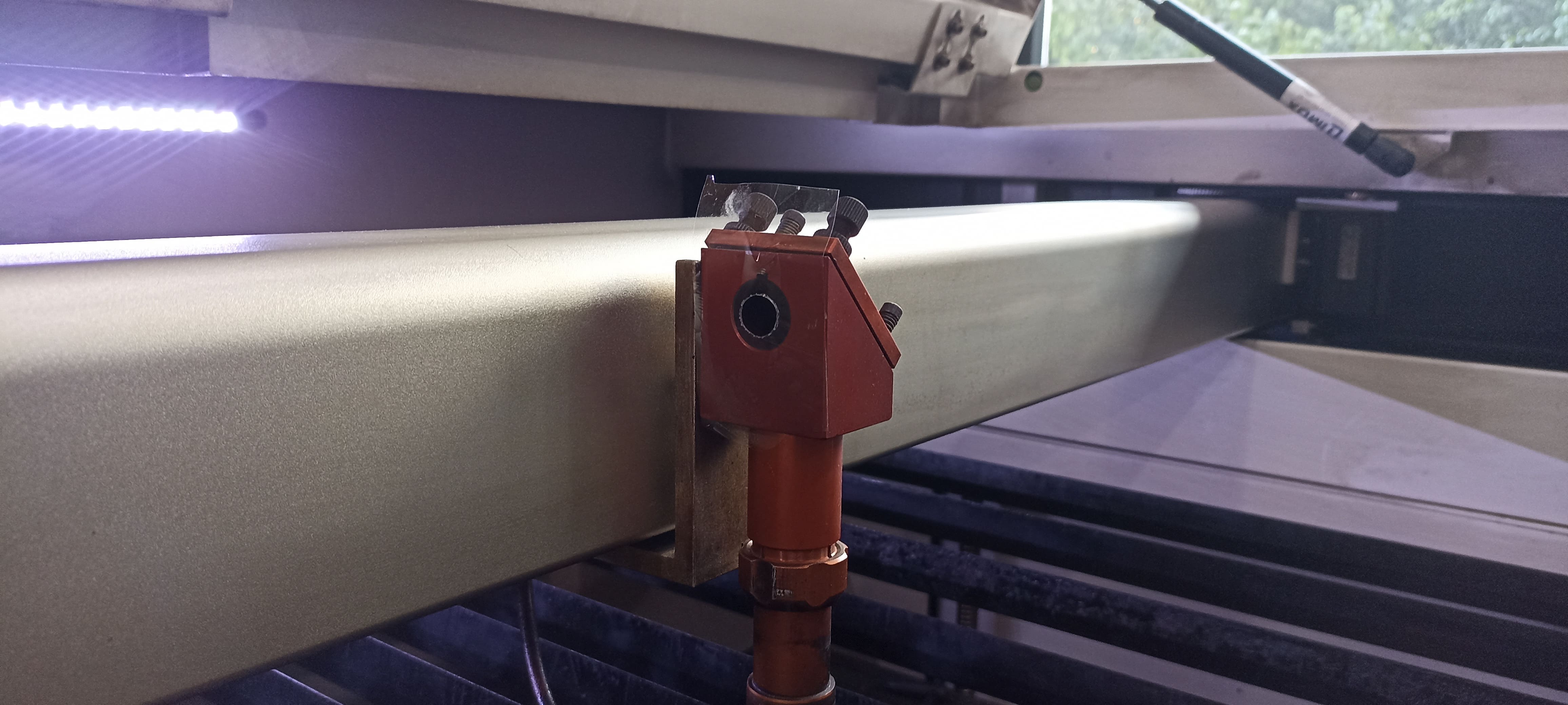
Remembering that these lasers have a focal point, we must use the notch to adjust the height. This is the original one from the machine, which allows adjustments for multiple materials.
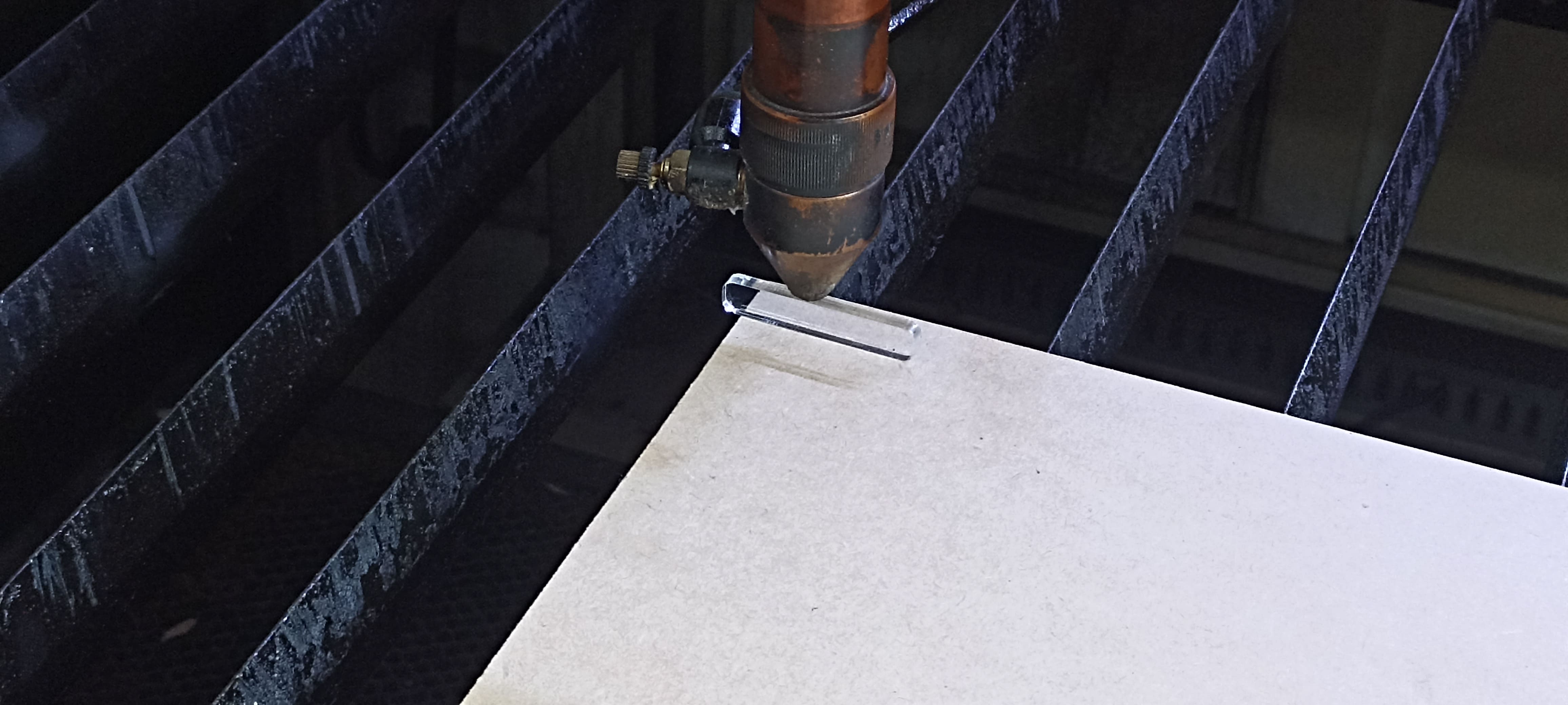
However, I created my own specific notch for this material, with a distance of 7 mm, which has given me the best results.
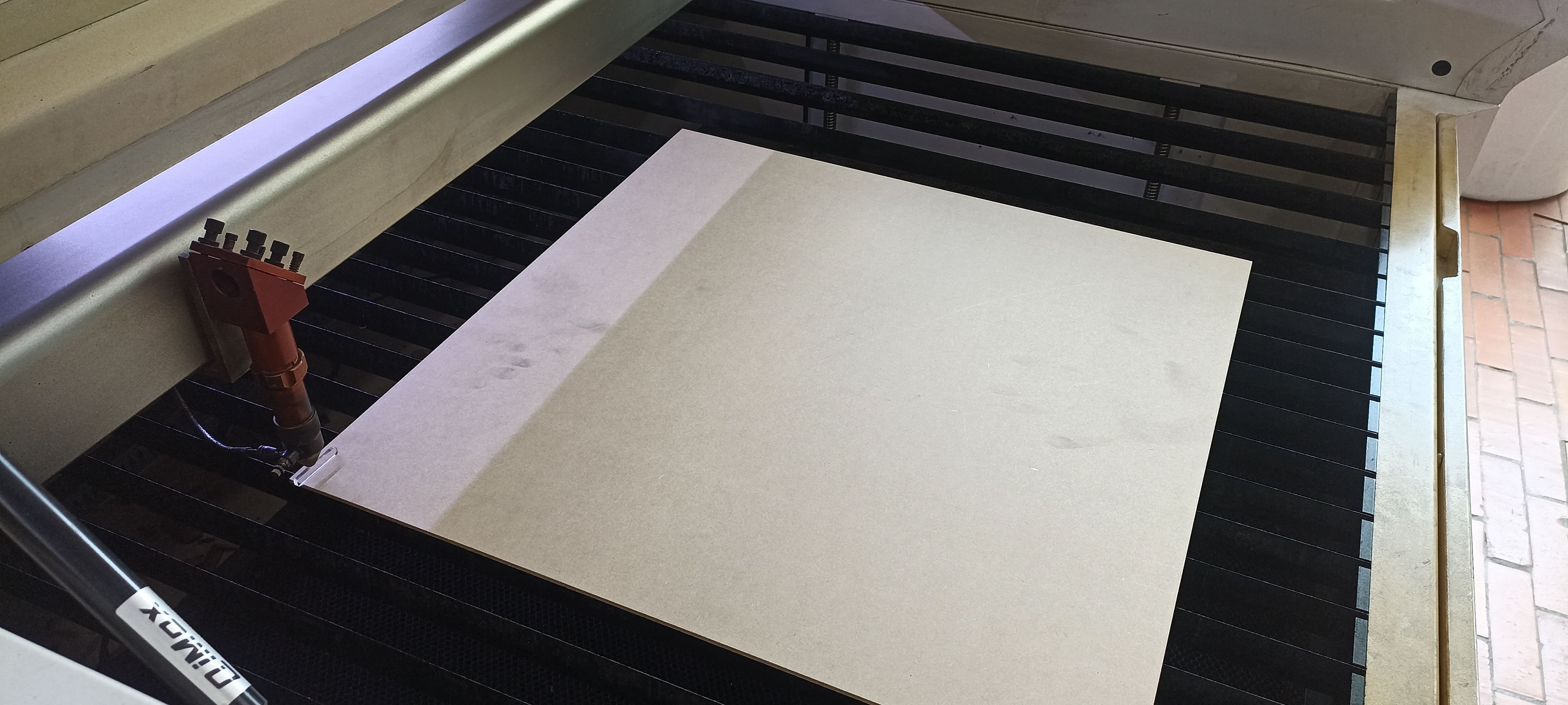
After setting the focus point, I carefully adjust the material along its length and width to ensure that the work I will do actually fits within the available material.
As mentioned earlier, there have been accidents, which is why we have a camera to monitor and supervise the machine remotely.
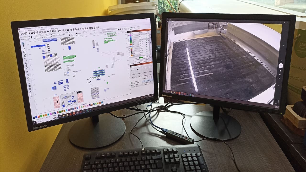
We can do this from the machine’s computer or remotely, ensuring safe operation.
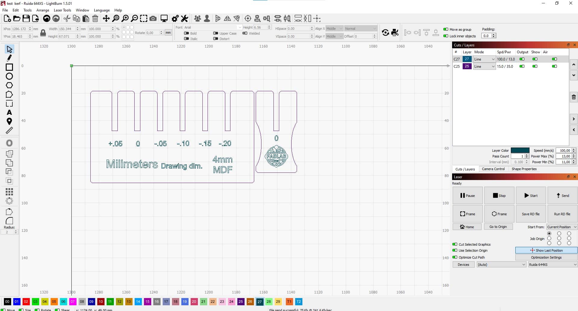
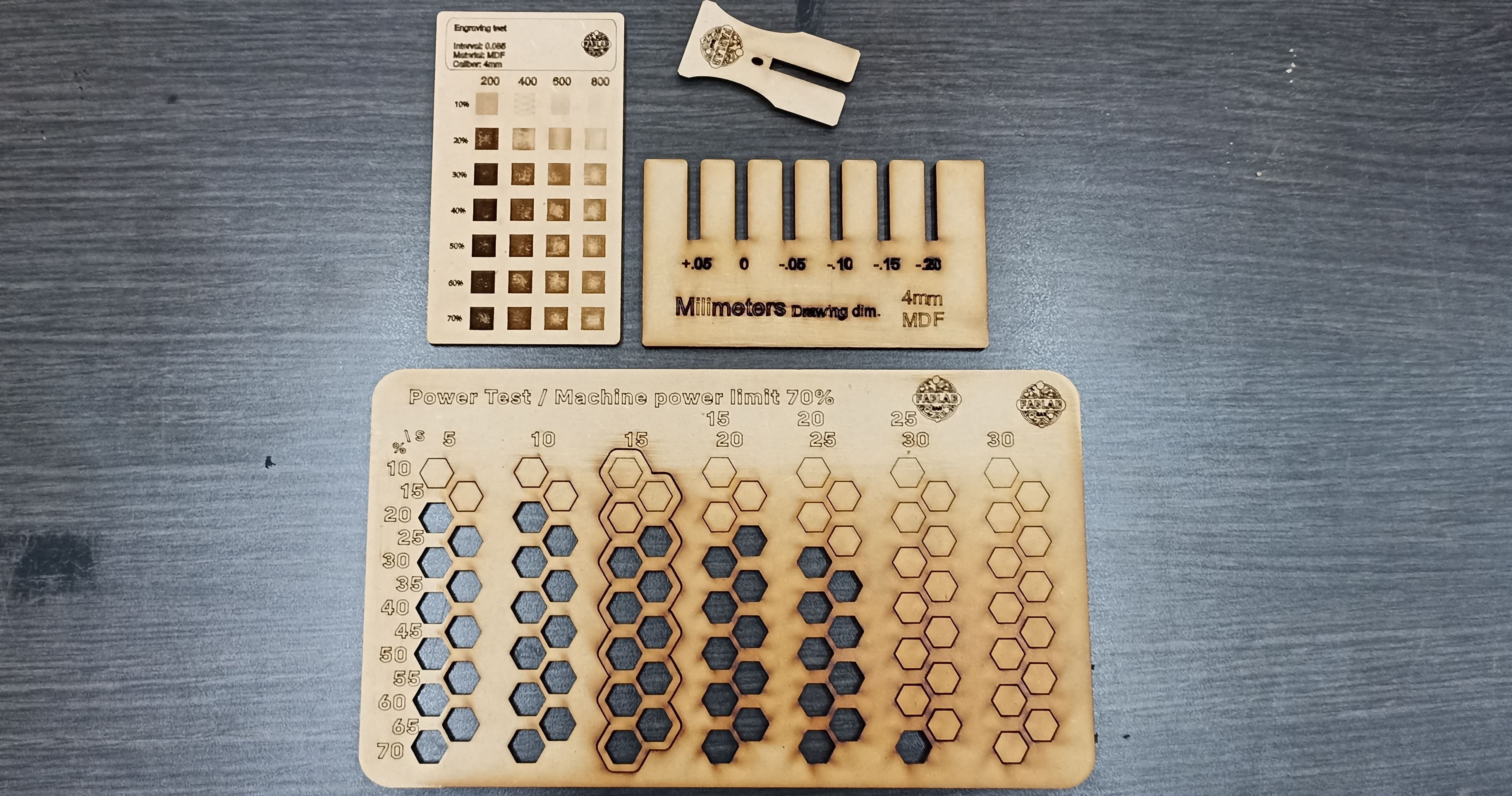
I designed my own kerf test to determine the correct tolerance for assembling the MDF pieces.
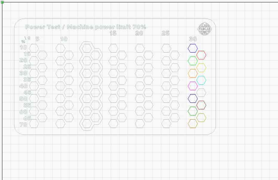
I also designed my own cutting power test, using hexagons as the basis.
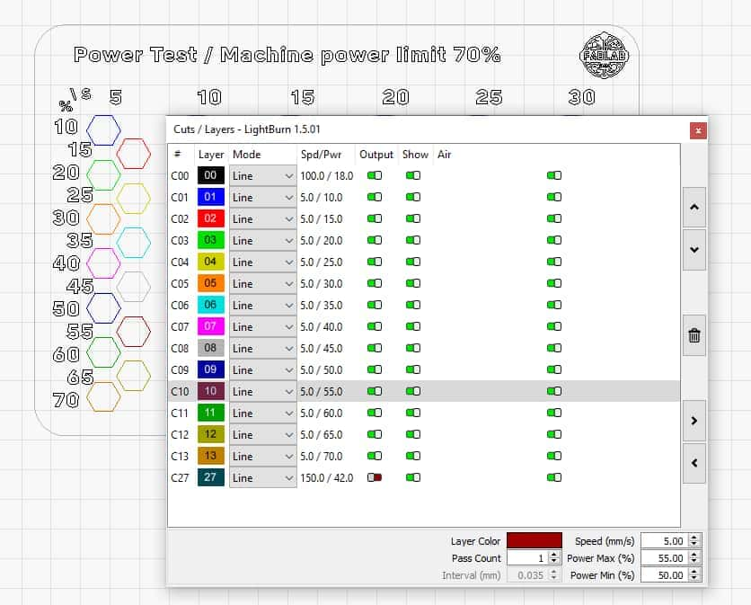
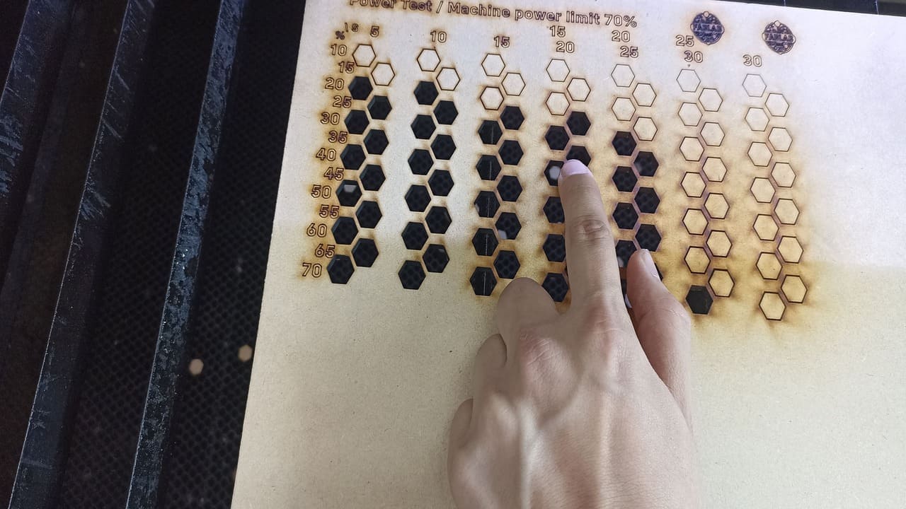
I adjusted the different power levels box by box, and I did it section by section to avoid mistakes (although I did make some).
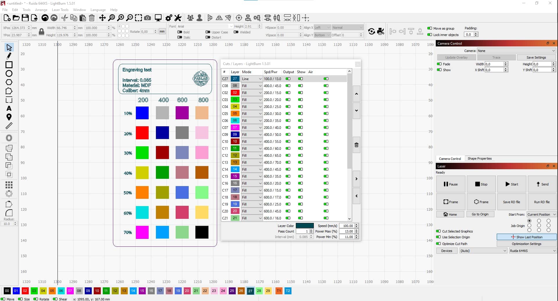
I also followed the same process for an engraving or fill test.
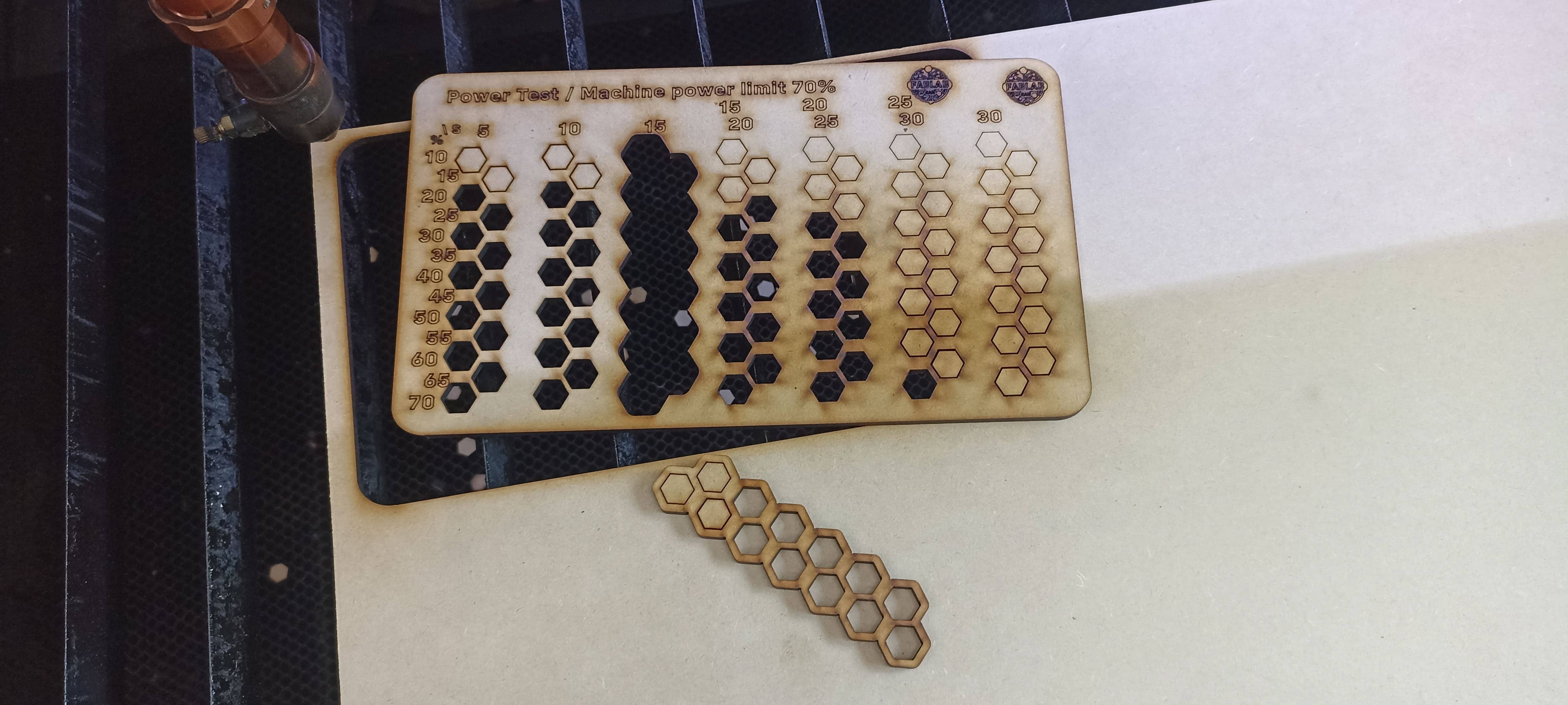
As I mentioned earlier, at one point I got confused because there were far more boxes than the software could handle, so I had to work in sections and cut out the failed part.
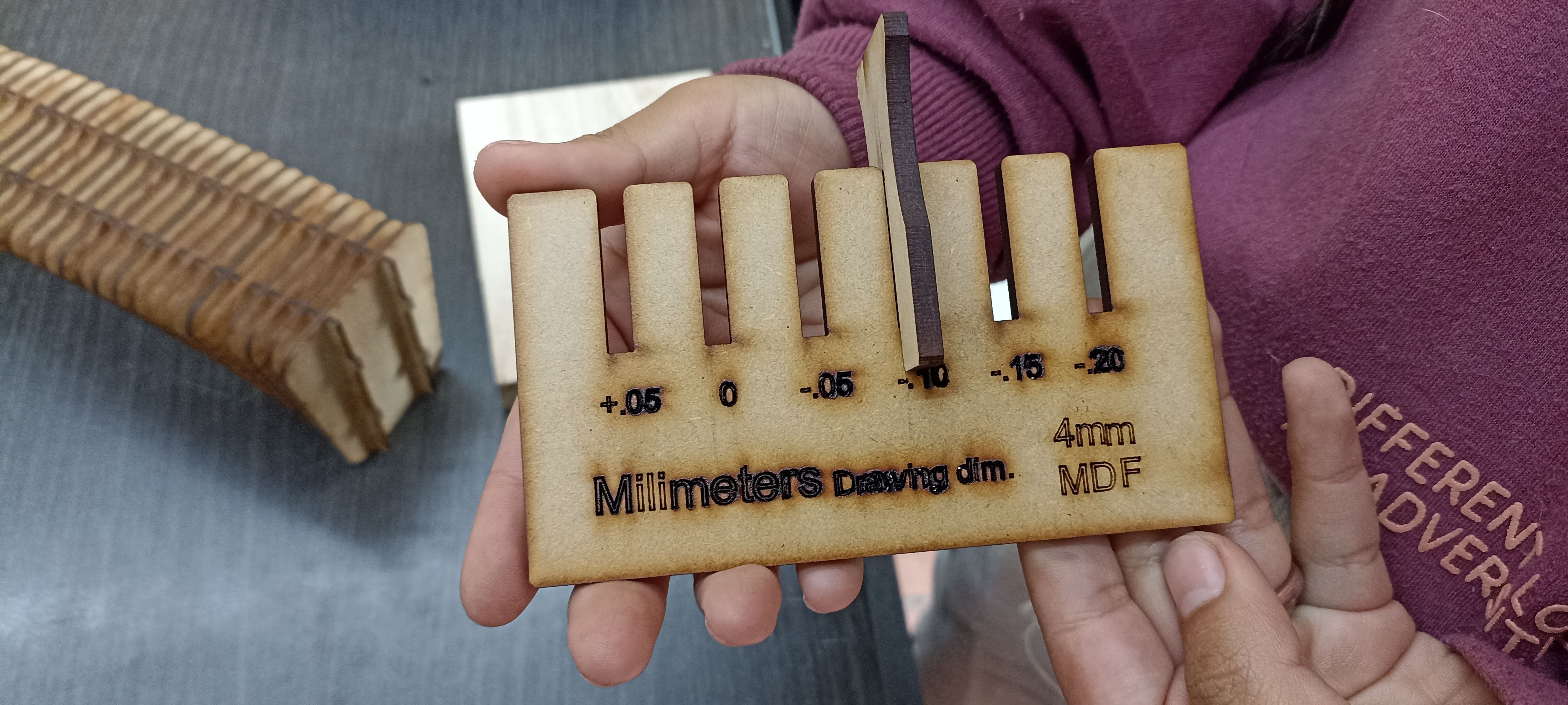
In the end, I determined that the best tolerance is -0.15 mm, achieving a precise fit without requiring too much force.
For laser cutting, I selected a medium power setting to operate the laser at a good speed: as fast as possible and with the least power necessary to cut well.
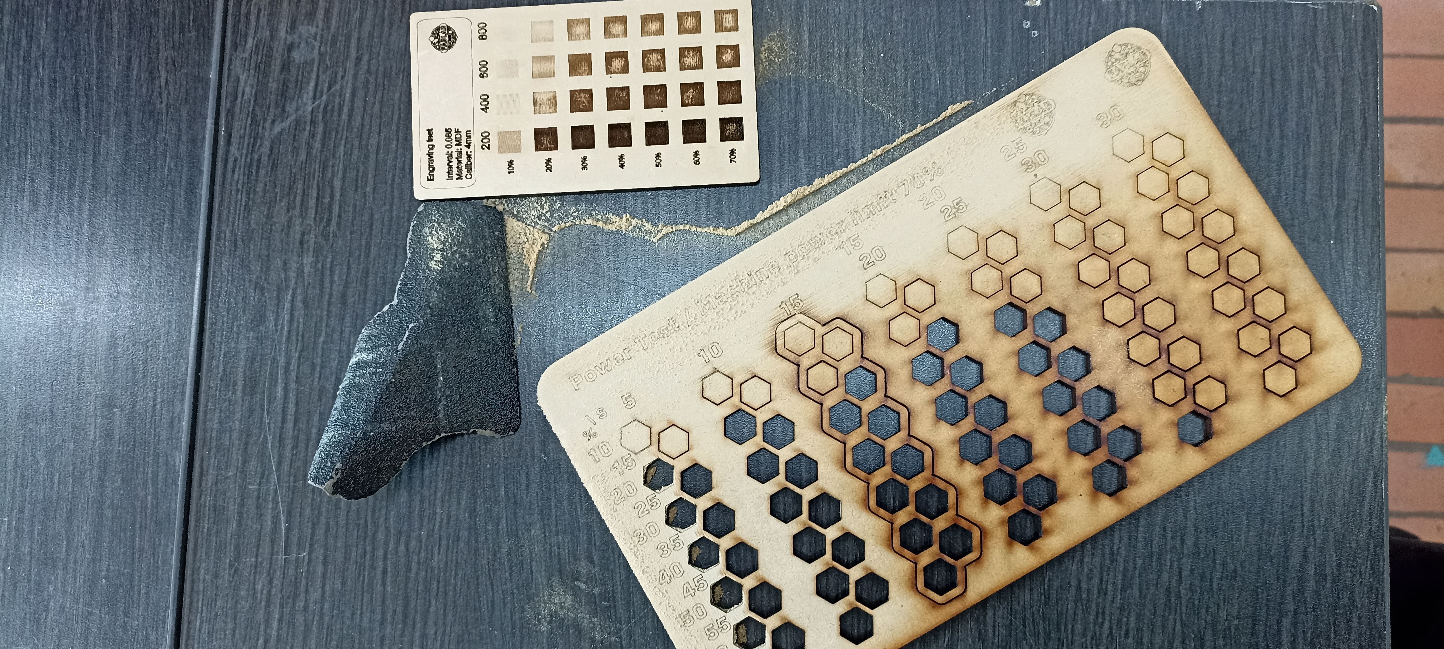
Since the pieces came out slightly burned, I sanded them to smooth the surface and make the text easier to read.
And these are all my tests, including even the part I had to cut out to avoid mistakes.
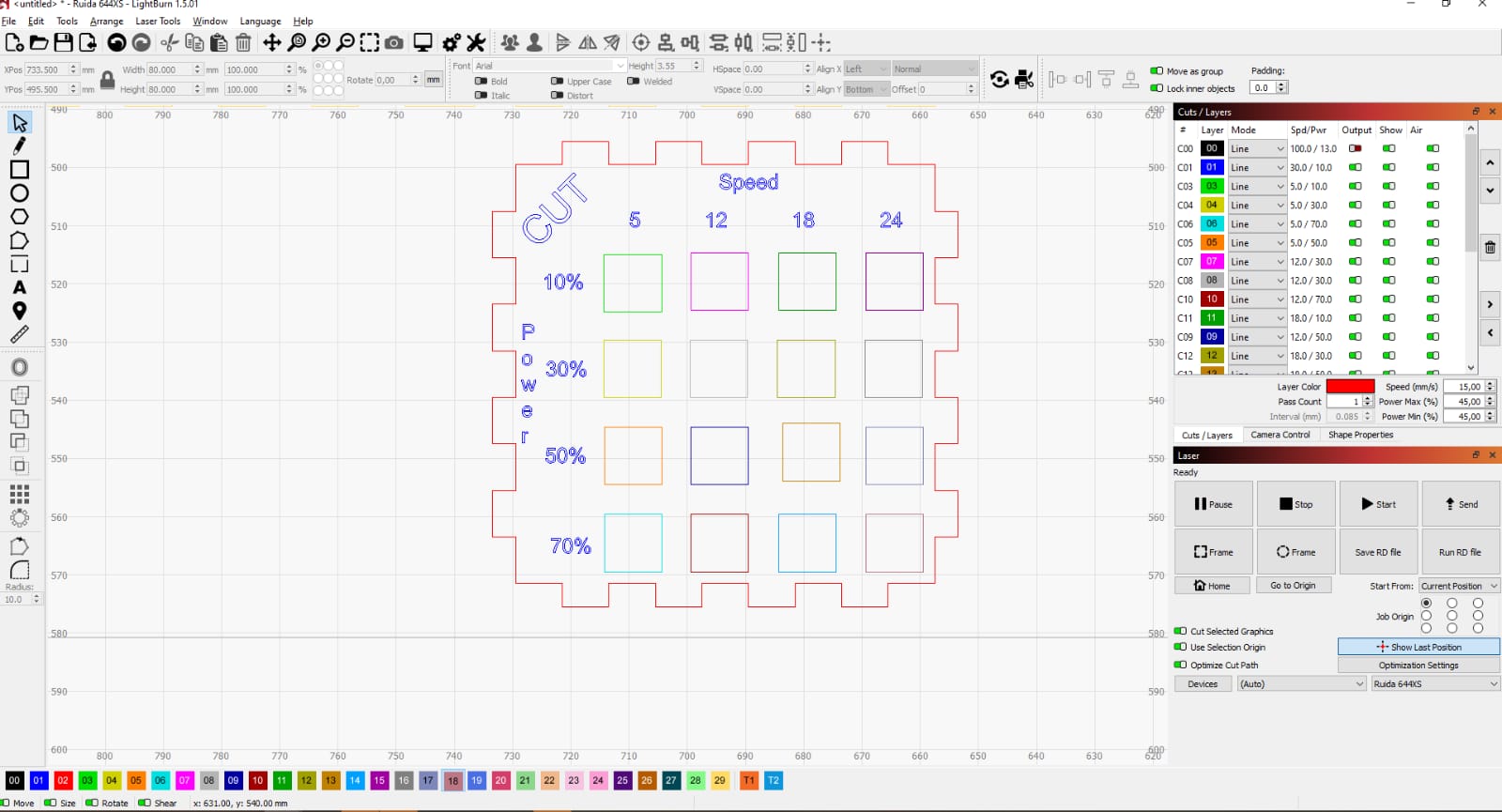
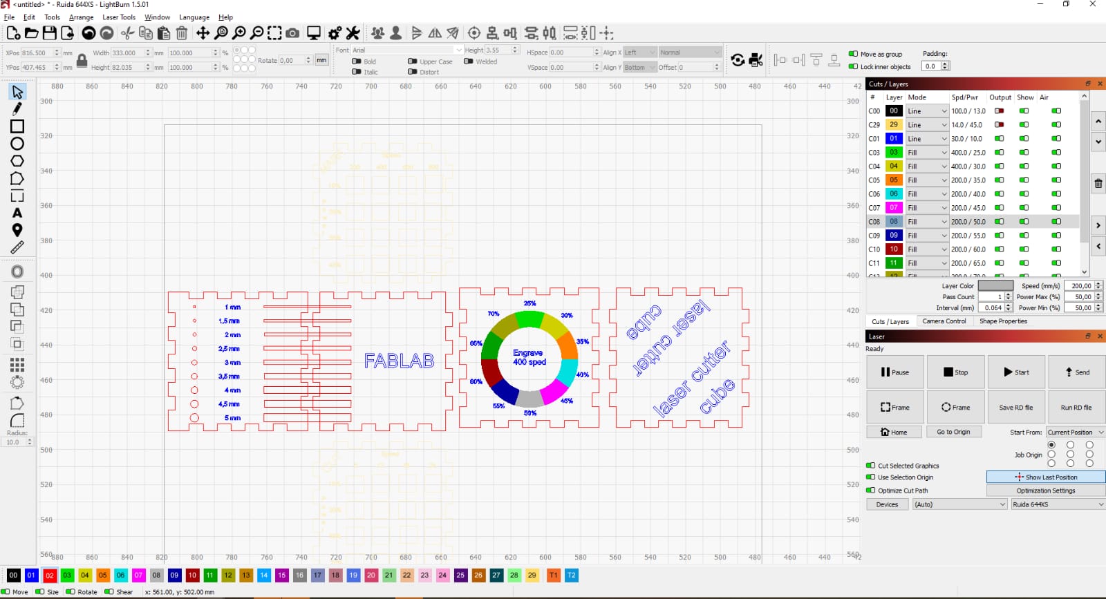
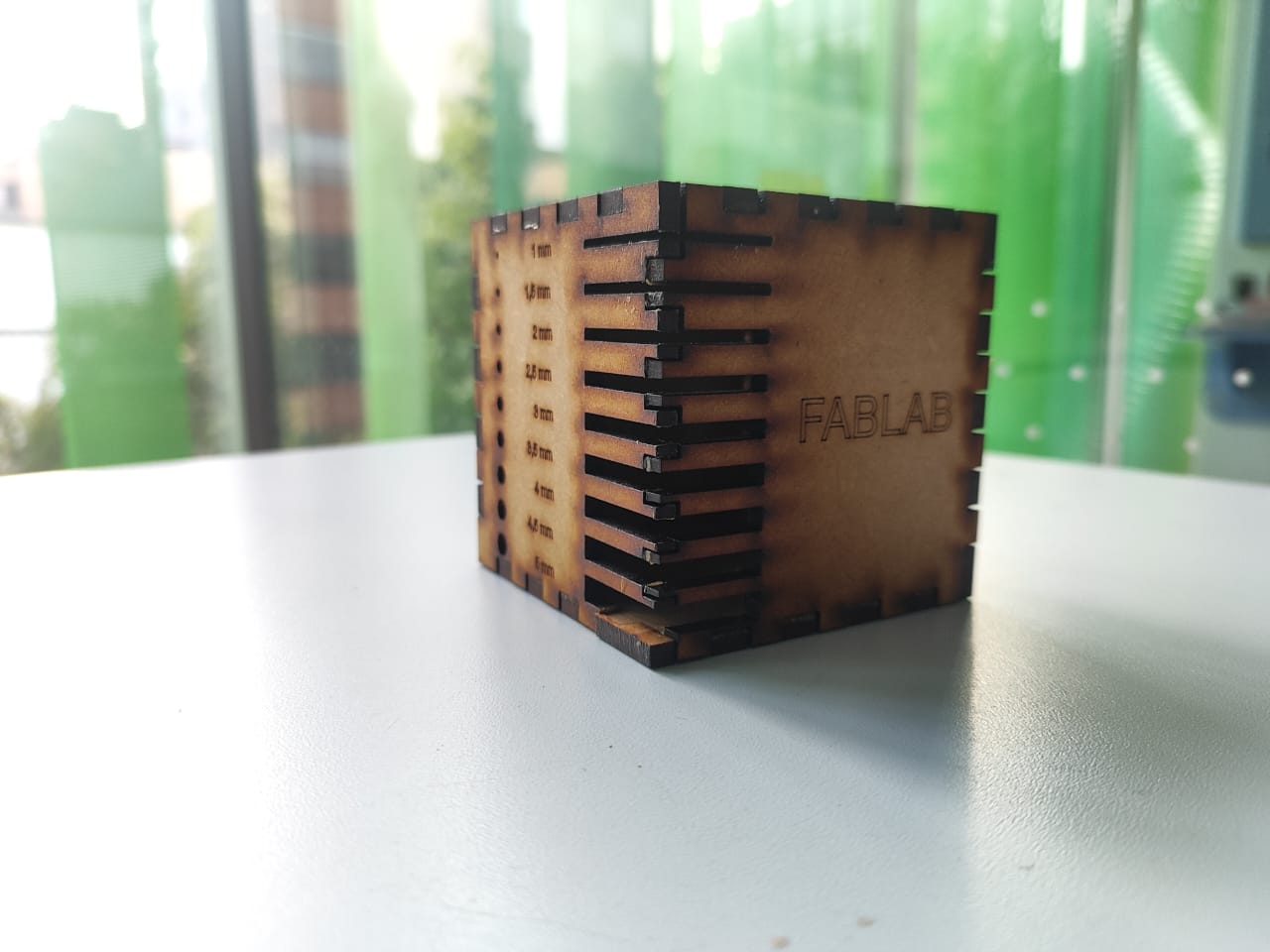
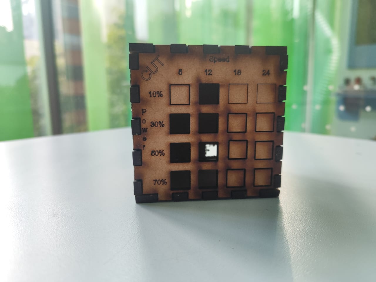
The contribution of Andrés Felipe Guarnizo to the group work consisted of building a cube to be able to measure the different speeds, marking, engraving, power and additionally to be able to determine the widths I need to fit the various pieces.
After the whole design process, I proceeded to make the cuts and engravings on the machine, obtaining the following results.
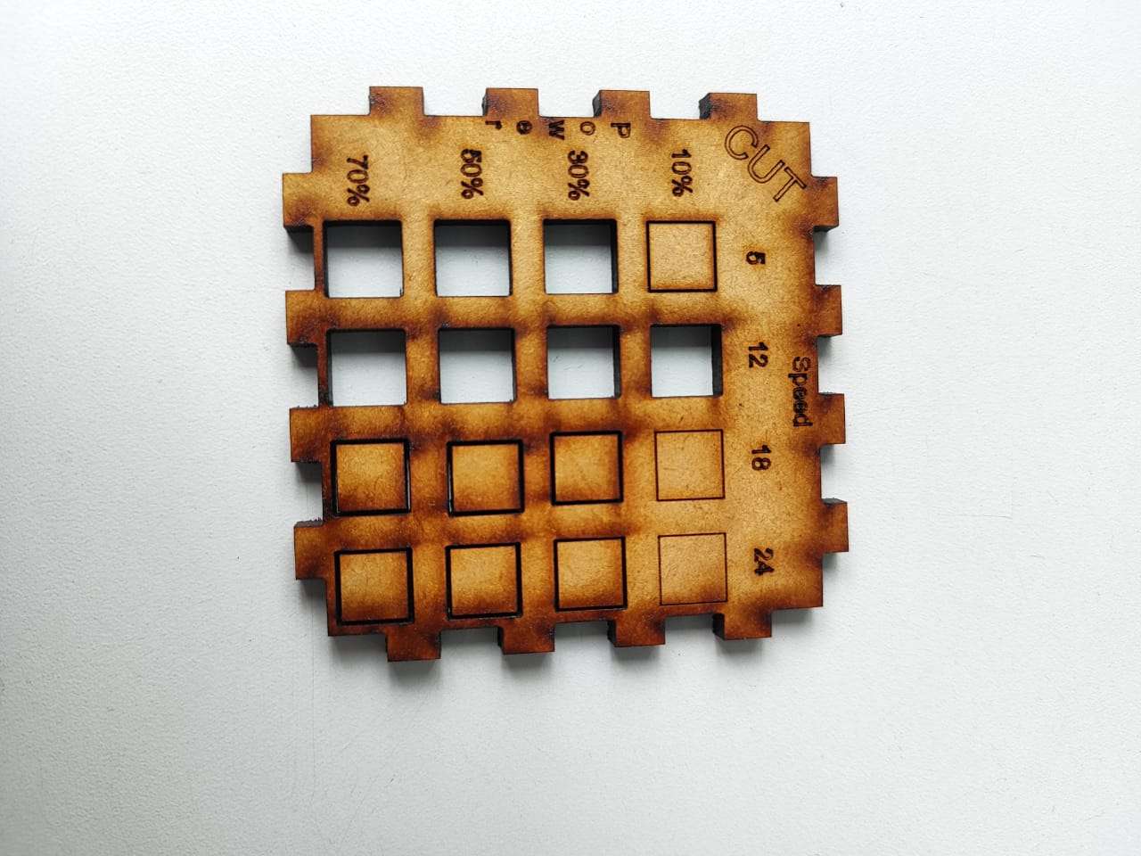
Based on the results obtained from the test cube, it was observed that at a power setting of 30% and a speed of 5 mm/s, the material is successfully cut. However, although the material is also cut at a power of 70% and a speed of 12 mm/s, the area surrounding the cut becomes visibly burned. This significantly reduces the aesthetic quality of the piece due to excessive charring around the edges.
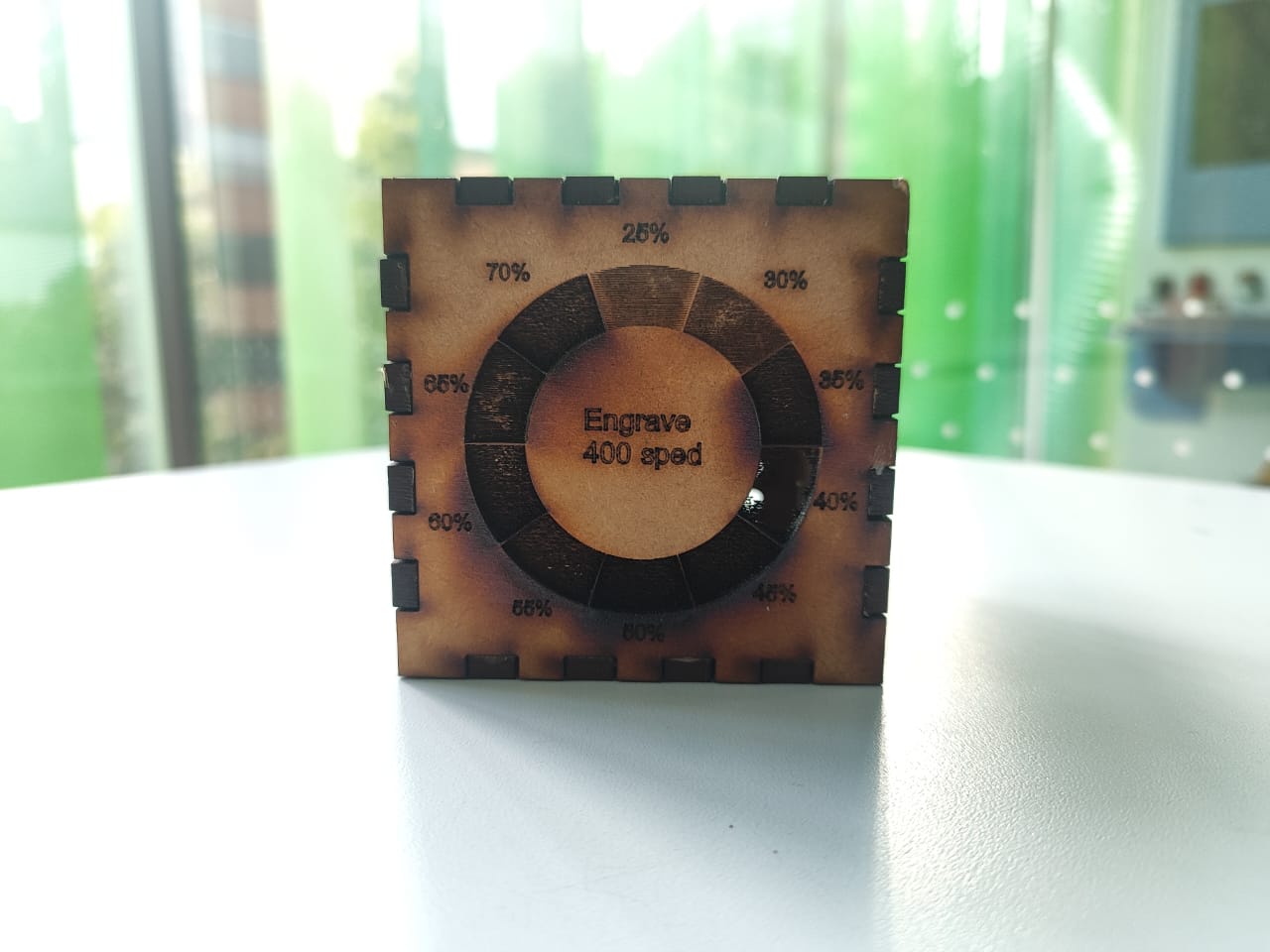
Regarding engraving with a constant speed of 400 mm/s, it was observed that using a power setting of 25% is sufficient to produce a light and subtle mark on the material. If a slightly deeper or more noticeable engraving is desired, increasing the power to 30% yields a more pronounced result. However, beyond this point, significant material loss becomes evident, and considerable variations in depth begin to appear, affecting the uniformity of the surface.
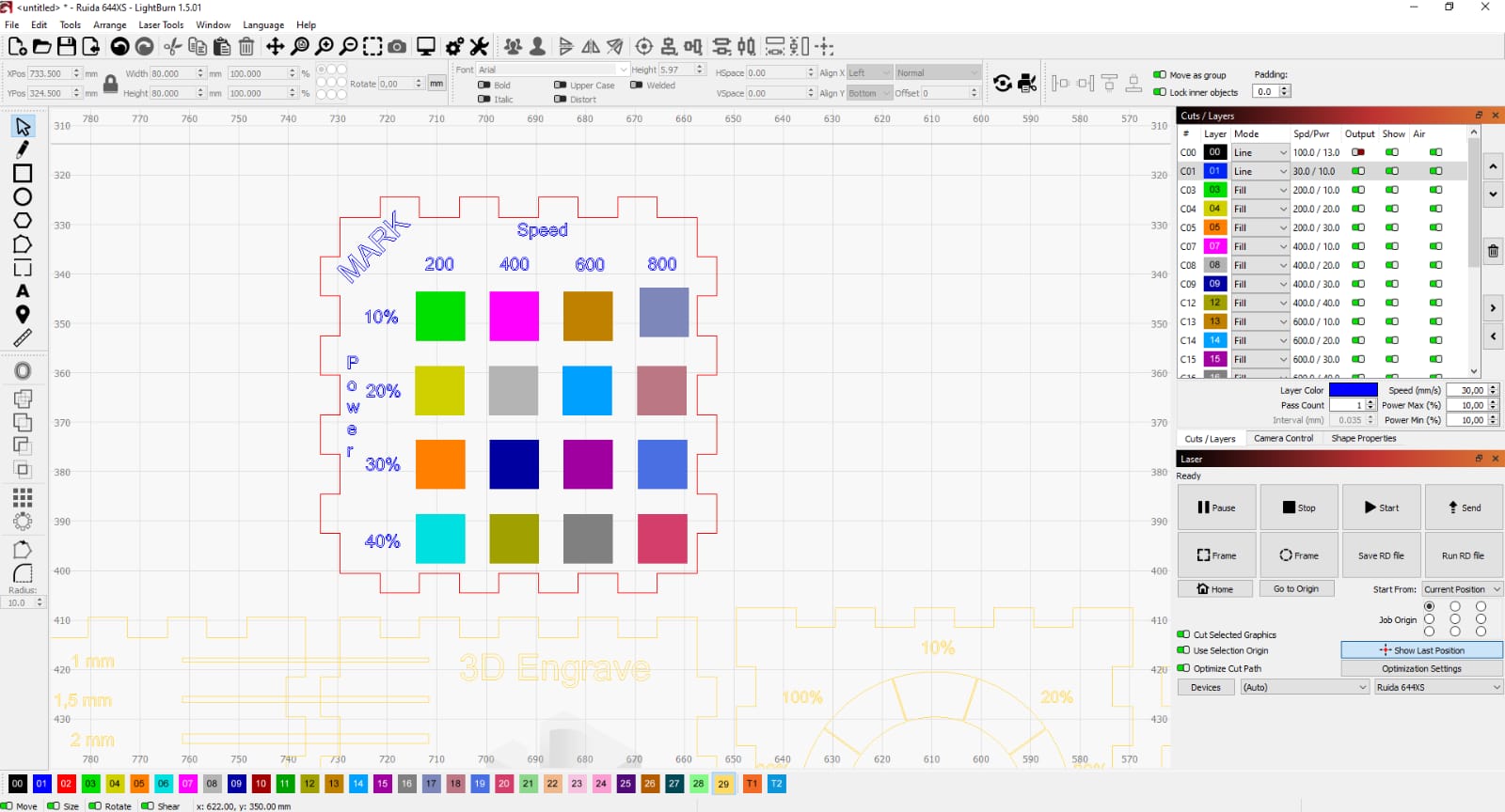
Regarding the marking test, it was observed that a configuration of 600 mm/s speed and 30% power provides a good result. Although it slightly reduces the surface height, it achieves a clean and well-contrasted mark. Other settings, such as 600 mm/s with 40% power, also produce acceptable results. However, using low-speed and moderate-power values—such as 200 mm/s and 30% power—causes damage to the material and is not recommended for marking purposes.
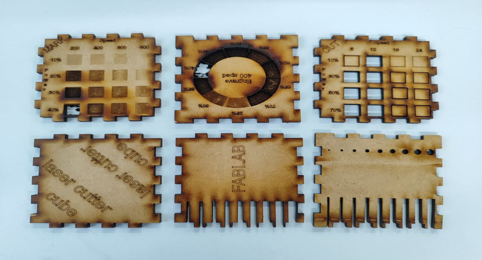
Finally, during the test to determine the optimal spacing in a cut that ensures parts remain firmly in place, it was concluded that a separation of 4 mm offers the best result. This measurement provides enough friction between the pieces to hold them together securely without the need for adhesives or fasteners.

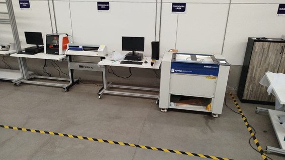
The image shows a digital fabrication workspace equipped with cutting and engraving devices, specifically an Epilog Fusion M2 laser cutter and a Roland vinyl cutter. Both machines are connected to workstation computers for software control. The area is clearly marked with yellow and black safety tape on the floor, indicating the safe operation zone and warning of the use of high-risk equipment.
FabLab Indoamérica
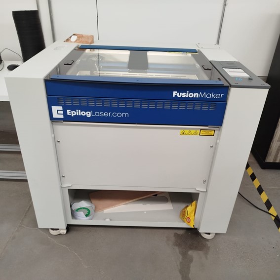
The image shows an Epilog Fusion Maker, a CO₂ laser cutter and engraver commonly used in FabLabs. It features a transparent lid for visibility, safety labels on the front, and a lower storage compartment with materials. The machine is placed in a clearly marked safety zone, reflecting a clean and organized workspace.
Prohibited Materials: PVC, polycarbonate, and materials that release toxic fumes.
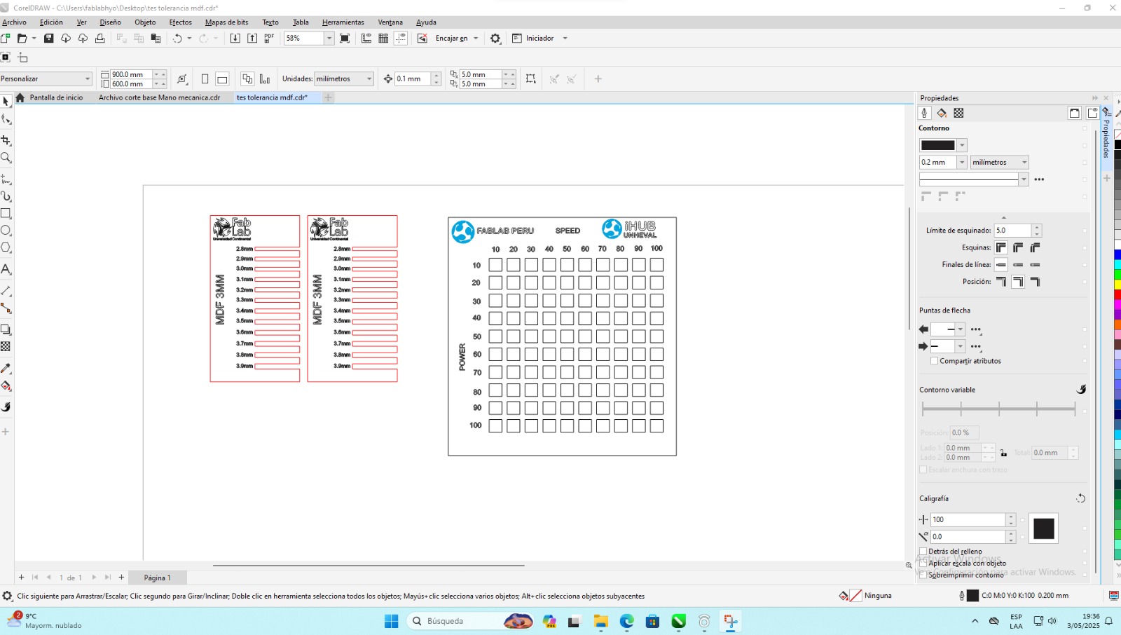
Displayed in the first image, the power vs. speed test grid is used to determine optimal settings for different materials.
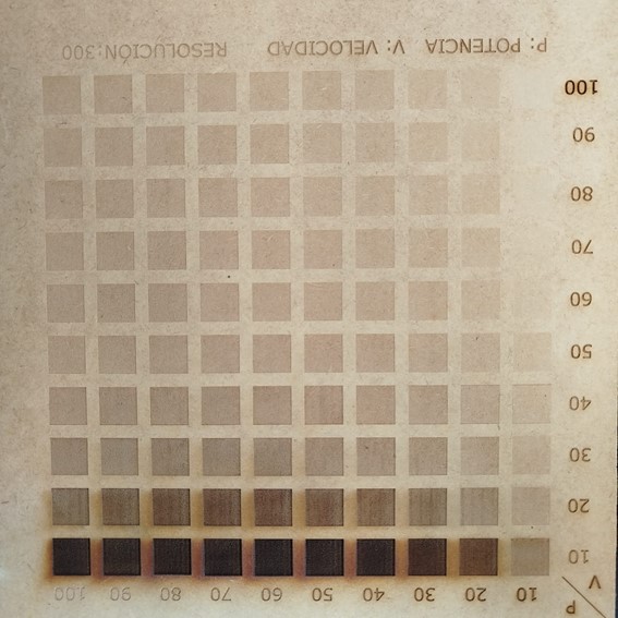
The image shows a laser engraving test grid used to calibrate power and speed settings on a material. The vertical axis represents power percentage (10–100%), and the horizontal axis shows speed percentage (10–100%). The result helps determine optimal engraving settings by analyzing contrast and burn depth variations at different configurations.
FabLab Indoamérica
This experiment aims to determine the optimal fit for interlocking laser-cut pieces by testing different slot widths and evaluating tolerances.
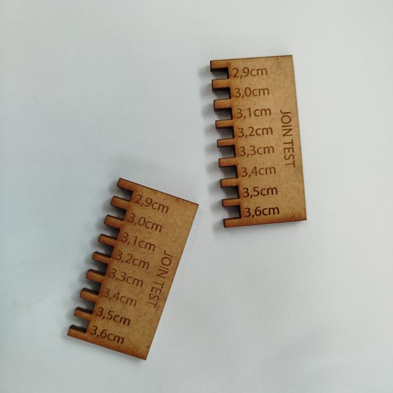
The image shows two laser-cut join test pieces made of MDF or similar wood-based material. Each piece features a series of interlocking notches labeled with dimensions ranging from 2.9 cm to 3.6 cm, allowing the user to test which slot size provides the best press-fit joint. This type of calibration tool is commonly used in digital fabrication to determine the optimal kerf compensation and ensure tight, accurate mechanical connections between laser-cut parts.
This test is essential for achieving precise fits in interlocking structures such as furniture, enclosures, and mechanical joints. Adjusting design files based on these results ensures accurate assembly and functional strength.