
(Includes: mechanism + actuation + automation + application)
Would you like to see our contributions? Here are the links so you can check them out: Evelyn’s Link / Armando’s Link
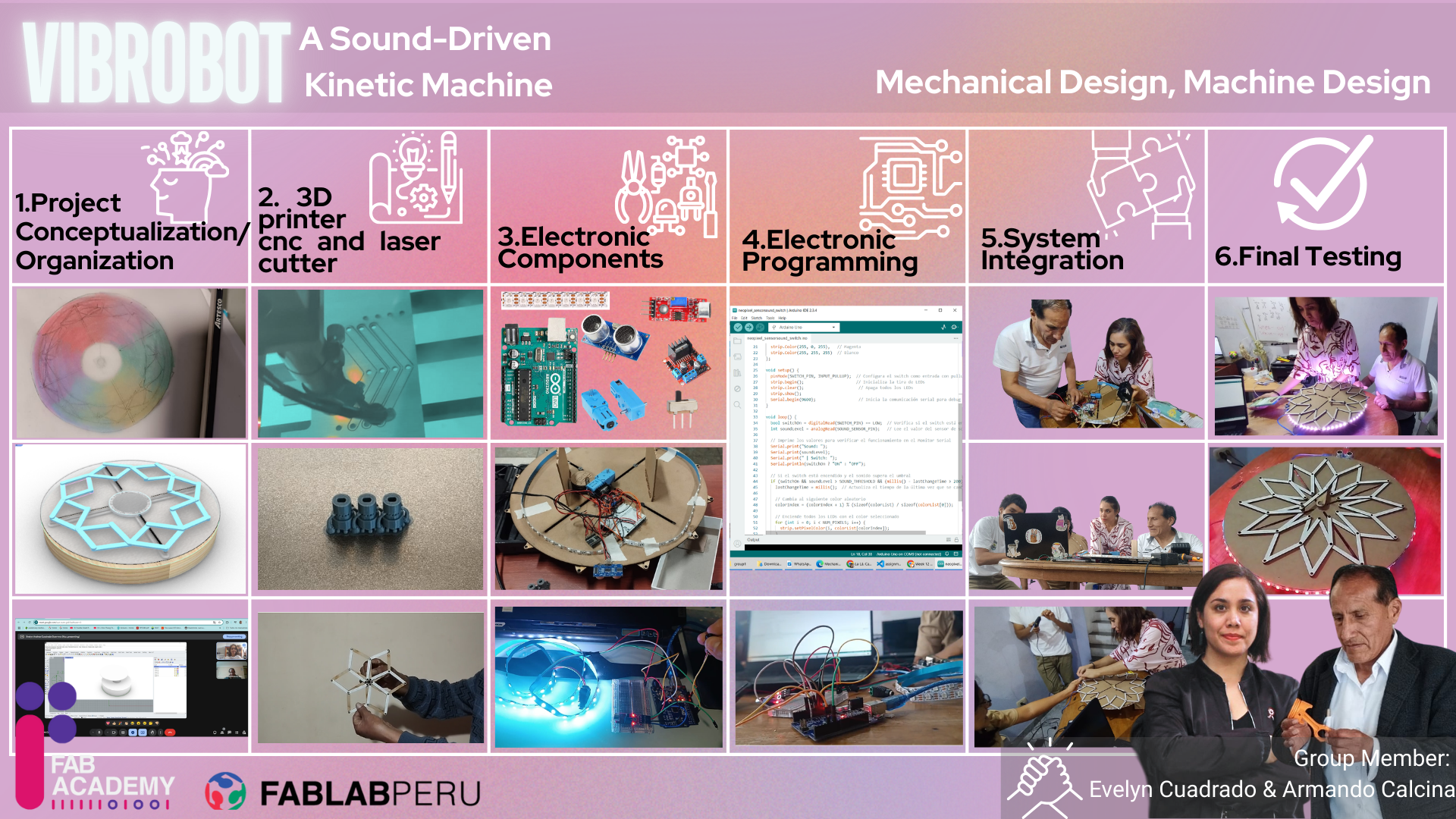
Summary video of VibroBot – A Sound-Driven Kinetic Machine, where you can see the full process in just 1 minute.
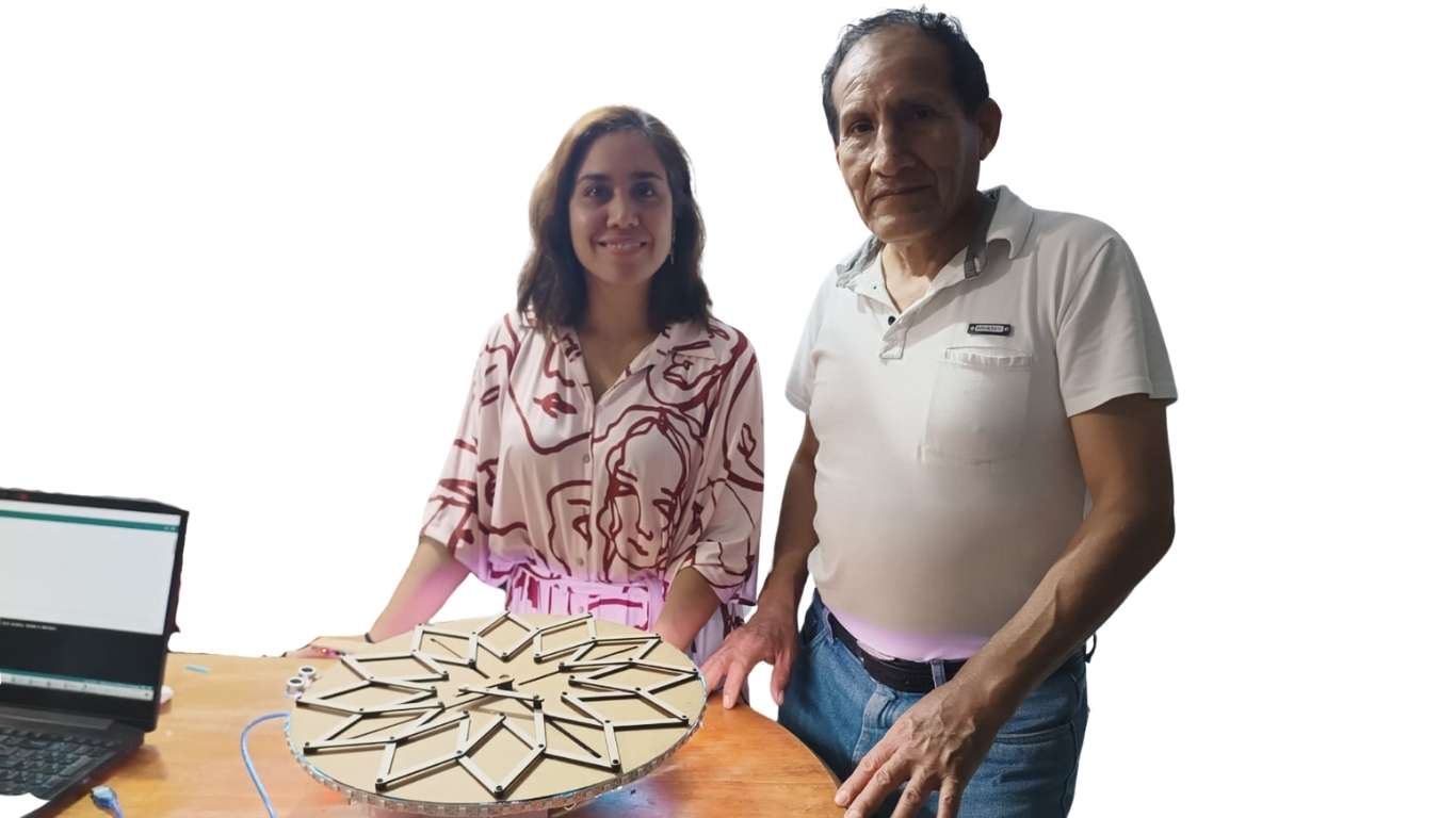
This project involves the design and construction of an interactive kinetic art machine that responds in real time to sound stimuli, such as music or ambient noise. It is a mechanical structure that integrates audio sensors, actuators, and a control system to transform sound waves into physical movement.
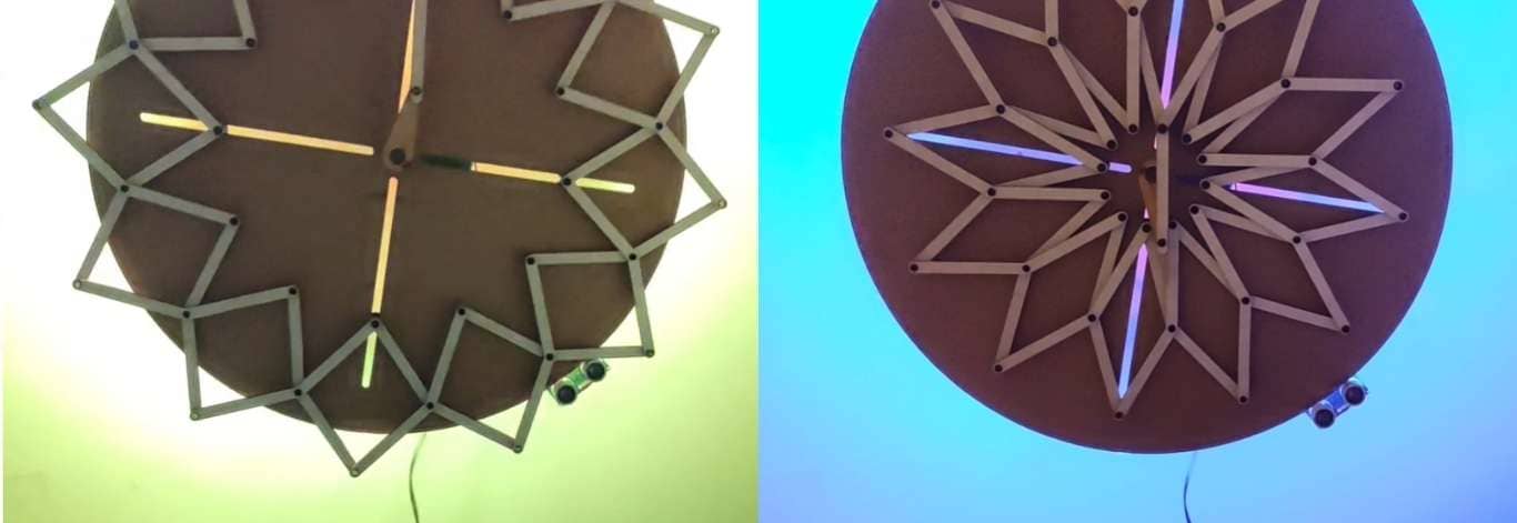
By capturing sounds from the environment, the machine generates dynamic responses through motorized mechanisms, creating visual patterns that evolve according to the intensity, rhythm, or frequency of the sound. This interaction turns auditory vibrations into a living visual experience, with the machine acting as a tangible extension of the acoustic environment.
Rather than being a static piece, this creation functions as an active entity that interprets sound and translates it into motion, forming a bridge between auditory and visual perception through technology.
The main purpose of this machine is to create an interactive experience that combines light, sound, and movement. By integrating these elements, the project seeks to engage users on multiple sensory levels, encouraging exploration, interaction, and emotional connection through a multisensory artistic expression.
The initial stage of the project focused on an intensive phase of brainstorming and visual research, aimed at exploring creative and technical possibilities for developing an interactive kinetic machine. This process was essential to define a clear and coherent direction for the final proposal.
During this phase, multiple ideas were generated around how to integrate art, technology, and movement, considering different types of interaction: visual, auditory, and physical. Concepts such as kinetic art, sound visualization, repetitive motion mechanics, and synchronization with environmental stimuli were explored.
At the same time, a visual research process was carried out using platform like Pinterest, where references were analyzed related to kinetic sculptures, interactive installations, and artworks that use light and sound as expressive media. This search helped identify visual styles, interesting mechanical systems, and methods of responding to external stimuli.
This phase concluded with the selection of a main idea: a kinetic machine that reacts to sound in real time, combining sensors, mechanical movement, and light effects to deliver a multisensory and immersive artistic experience.
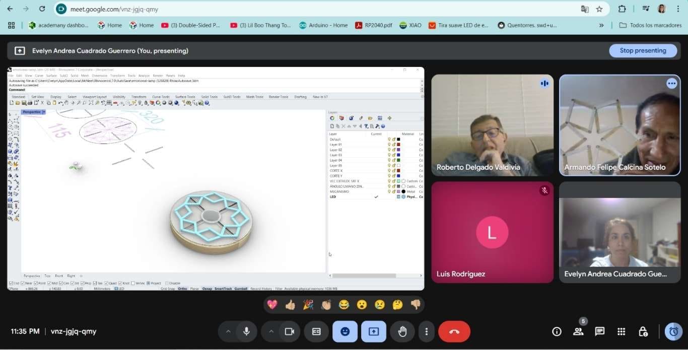
To improve our organization, distribute roles more efficiently, and define the project objectives more clearly, we held several key meetings with our instructors. These sessions were essential in the creative process, as they helped us ground our ideas and make realistic decisions based on our capabilities and the time available.
Since we were located kilometers apart, it was crucial to organize our work effectively. We created an activity schedule and timeline that allowed us to plan each phase of the project and maximize the available time. We only had one day to meet in person and assemble the machine, so we had to carefully coordinate our tasks and efforts.
With the support of Roberto, Cristian, Ulises, and Luis Miguel, we received valuable guidance to assign tasks according to the activities we had already been working on individually. Their input allowed us to collaborate in a more coordinated way, optimize our time, and make the most of each team member’s strengths.
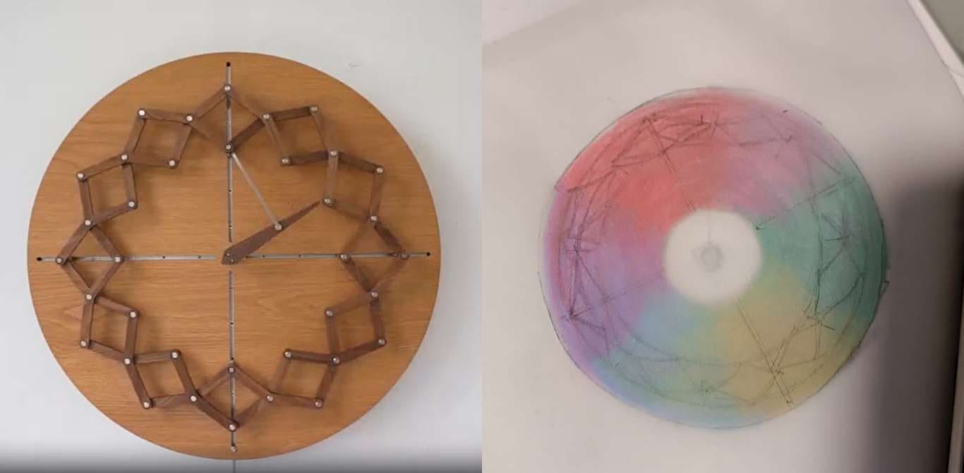
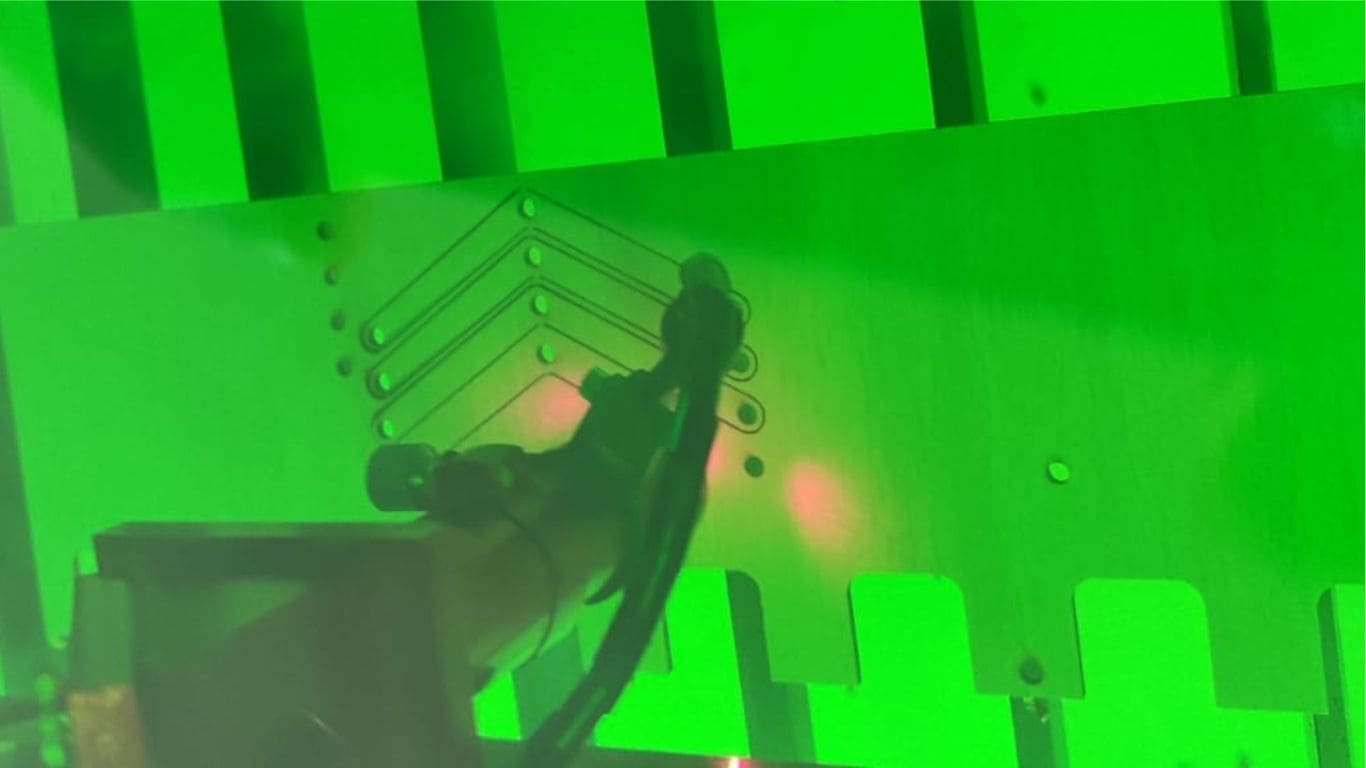
The mechanism is driven by a rotational motor connected to a clockwork-style system. This setup allows the structure to repeatedly expand and contract. Due to the specific kinematic design of the mechanism, this motion is not limited to a single axis; instead, it simultaneously produces movement along both the X and Y axes. In other words, as the structure expands and contracts, it also slides diagonally or across both axes, creating a multidirectional effect.
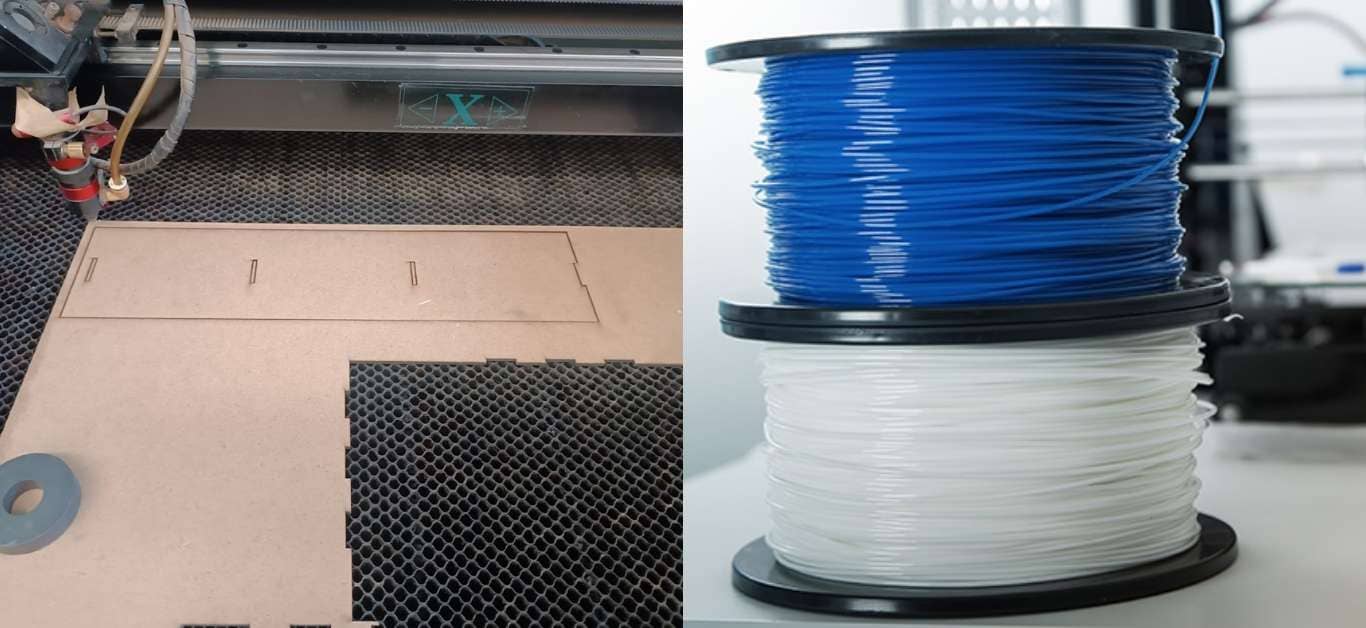
The material chosen for building the machine’s structure is MDF (Medium-Density Fiberboard), selected for its ease of machining, dimensional stability, and cost-effectiveness. Meanwhile, the rivets and connecting components will be produced using 3D printing with PLA filament, allowing for custom-designed joints and a precise fit between moving parts. (The photo of the PLA material was taken from the internet.)
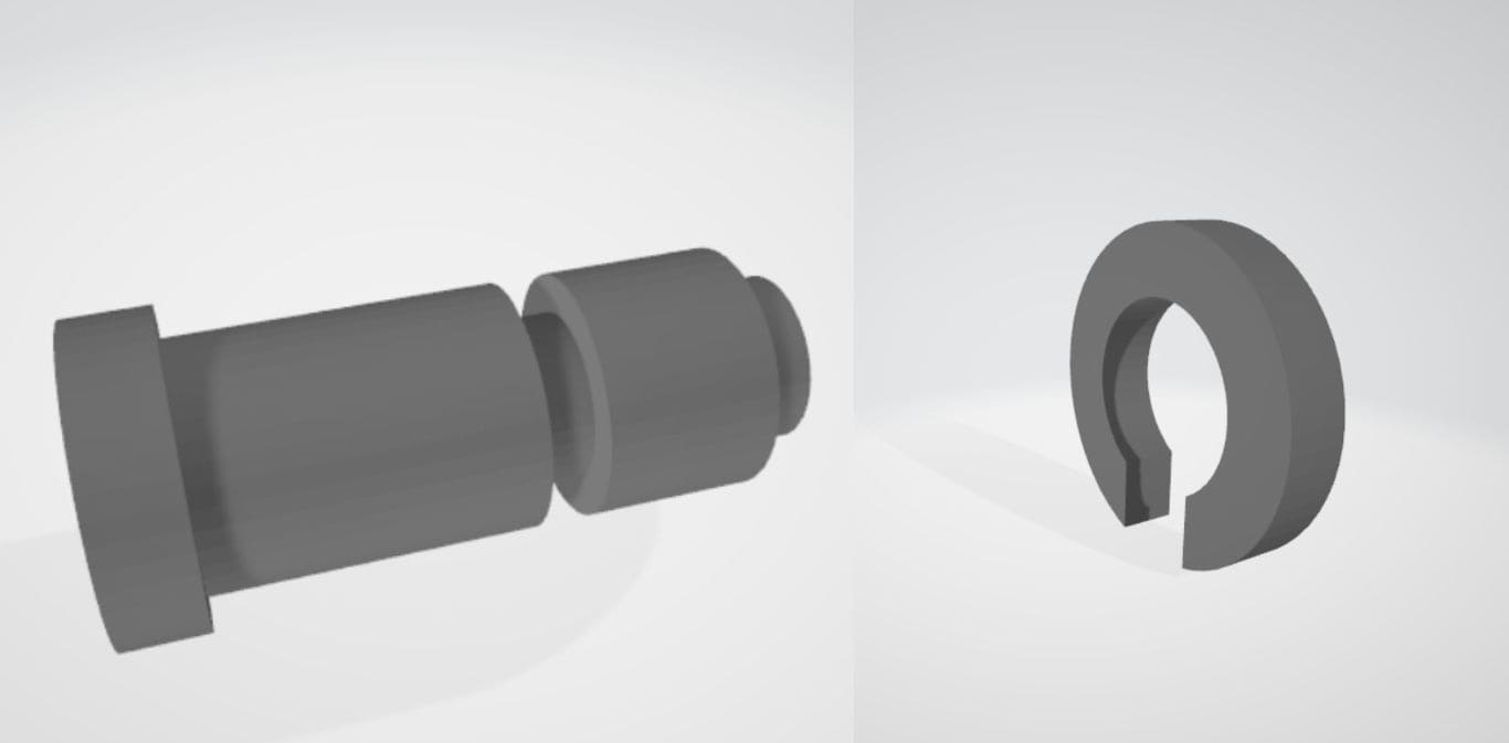
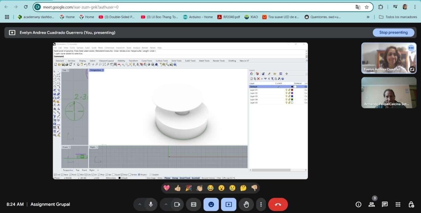
The modeling was done in SolidWorks software for the design of the rivets.
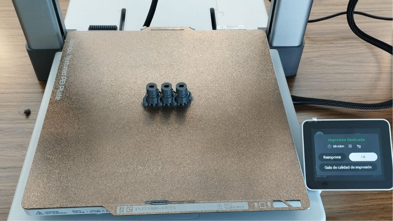
Subsequently, they were manufactured using a 3D printer.
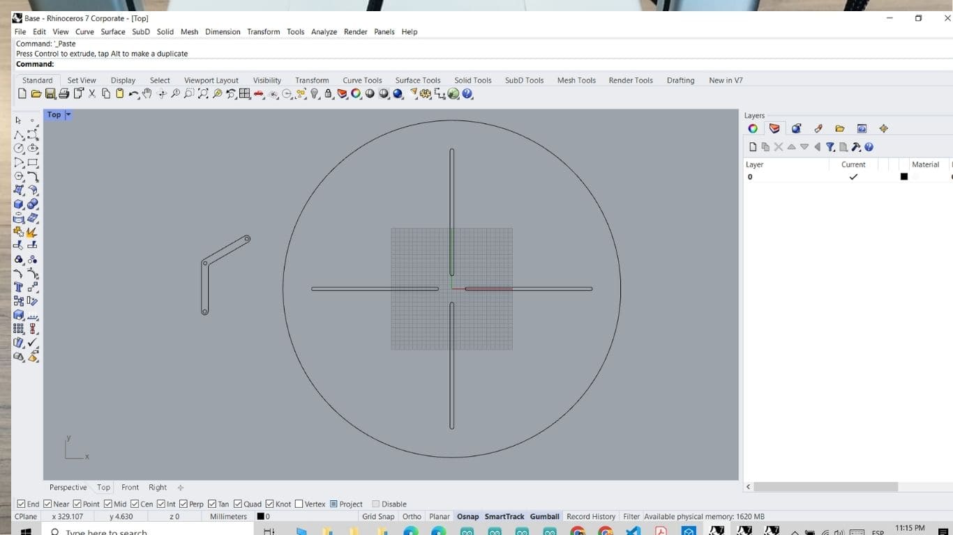
The design of the parts that make up both the structure and the mechanism was also completed.
These components were cut using laser technology to ensure dimensional accuracy and proper fitting. With this, all parts are now ready to begin the assembly process.
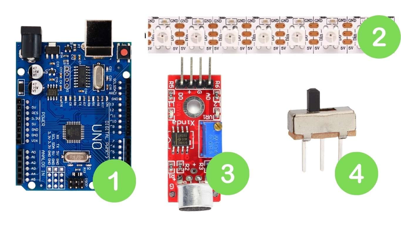
🔧 Electronic Components Used (Evelyn)
Main microcontroller that handles the entire logic and control system.
Individually addressable RGB LEDs used to create synchronized and dynamic lighting effects.
Detects ambient sound intensity; provides both analog and digital output.
Used to manually control system functions, such as activation or power.
| Component | Description | Arduino UNO Connection |
|---|---|---|
| Neopixel Strip (WS2812B) | Individually addressable RGB LEDs used for dynamic lighting effects. | Data Pin → D6 VCC → 5V GND → GND |
| KY-038 Sound Sensor | Captures ambient sound intensity to trigger visual responses. | A0 → A0 (Analog) VCC → 5V GND → GND |
| 3-Pin Switch | Used to turn the system on or off, or activate a specific function. | Signal → D4 GND → GND VCC → 5V |
| Arduino UNO | Main microcontroller board that reads inputs and controls outputs. | Central controller for all components |
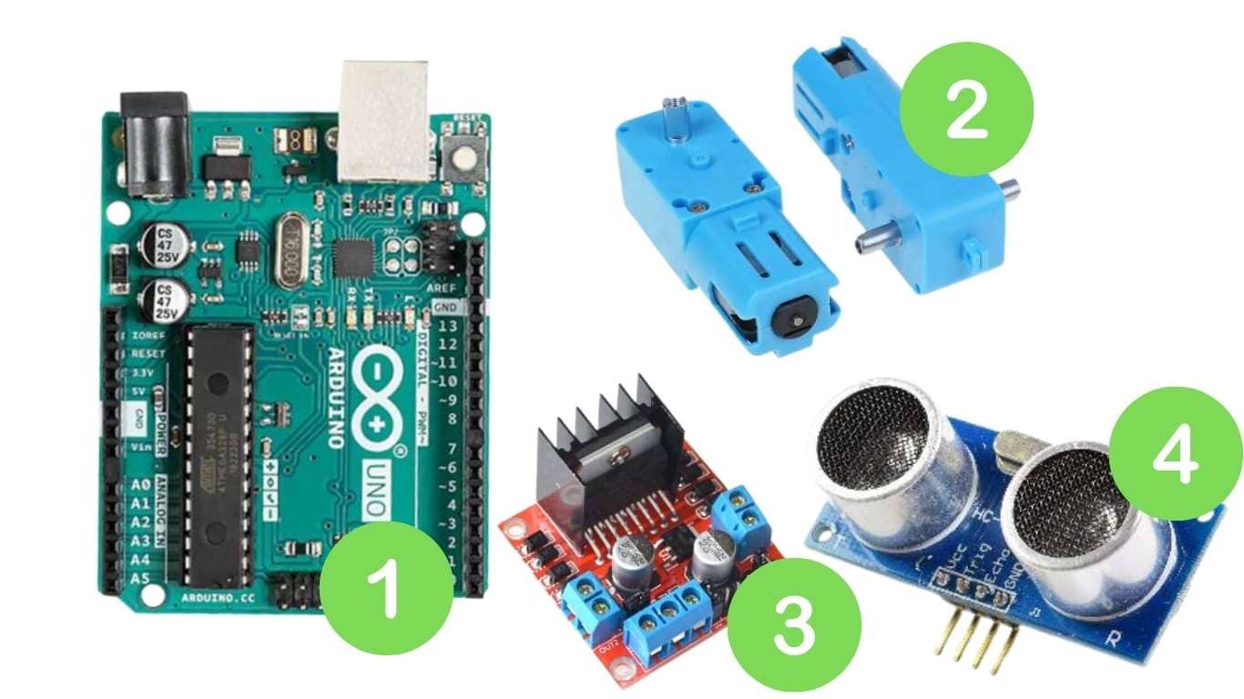
🔧 Electronic Components Used (Armando)
Main microcontroller board that manages all input and output operations in the system.
A DC motor with a metal gearbox for increased torque and precision in movement.
Dual H-Bridge motor driver used to control the speed and direction of the gear motor.
Measures distance to objects by emitting ultrasonic waves and reading the reflected signal.
| Component | Connection to Arduino UNO | Description |
|---|---|---|
| Metal Gear Motor | Connected to OUT1 and OUT2 of the L298N | DC motor with metal gears, controlled via the L298N driver |
| L298N Motor Driver |
|
Controls motor direction and speed |
| HC-SR04 Ultrasonic Sensor |
|
Measures distance using ultrasonic waves |
| Arduino UNO | - | Main microcontroller board that manages the entire system |
Develop and test sensor response and LED behavior.
            #include

                #define SOUND_SENSOR_PIN A0  // Pin analógico para el sensor de sonido
                #define SWITCH_PIN 2         // Pin del interruptor
                #define NEOPIXEL_PIN 6       // Pin para los LEDs NeoPixel
                #define NUM_PIXELS 60        // Número de LEDs en la tira
                #define SOUND_THRESHOLD 78  // Umbral de detección de sonido

                Adafruit_NeoPixel strip(NUM_PIXELS, NEOPIXEL_PIN, NEO_GRB + NEO_KHZ800);

                unsigned long lastChangeTime = 0;
                int colorIndex = 0;

                // Colores que se pueden usar (en formato RGB)
                uint32_t colorList[] = {
                  strip.Color(255, 0, 0),     // Rojo
                  strip.Color(0, 255, 0),     // Verde
                  strip.Color(0, 0, 255),     // Azul
                  strip.Color(255, 255, 0),   // Amarillo
                  strip.Color(0, 255, 255),   // Cian
                  strip.Color(255, 0, 255),   // Magenta
                  strip.Color(255, 255, 255)  // Blanco
                };

                void setup() {
                  pinMode(SWITCH_PIN, INPUT_PULLUP);  // Configura el switch como entrada con pullup
                  strip.begin();                      // Inicializa la tira de LEDs
                  strip.clear();                       // Apaga todos los LEDs
                  strip.show();
                  Serial.begin(9600);                  // Inicia la comunicación serial para debug
                }

                void loop() {
                  bool switchOn = digitalRead(SWITCH_PIN) == LOW;  // Verifica si el switch está encendido
                  int soundLevel = analogRead(SOUND_SENSOR_PIN);   // Lee el valor del sensor de sonido

                  // Imprime los valores para verificar el funcionamiento en el Monitor Serial
                  Serial.print("Sound: ");
                  Serial.print(soundLevel);
                  Serial.print(" | Switch: ");
                  Serial.println(switchOn ? "ON" : "OFF");

                  // Si el switch está encendido y el sonido supera el umbral
                  if (switchOn && soundLevel > SOUND_THRESHOLD && (millis() - lastChangeTime > 200)) {
                    lastChangeTime = millis();  // Actualiza el tiempo de la última vez que se cambió el color

                    // Cambia al siguiente color aleatorio
                    colorIndex = (colorIndex + 1) % (sizeof(colorList) / sizeof(colorList[0]));

                    // Enciende todos los LEDs con el color seleccionado
                    for (int i = 0; i < NUM_PIXELS; i++) {
                      strip.setPixelColor(i, colorList[colorIndex]);
                    }
                    strip.show();  // Muestra los cambios en los LEDs
                  } else if (!switchOn || soundLevel <= SOUND_THRESHOLD) {
                    // Si no hay sonido o el switch está apagado, apaga los LEDs
                    strip.clear();
                    strip.show();
                  }

                  delay(20);  // Pequeña demora para suavizar la lectura
                }
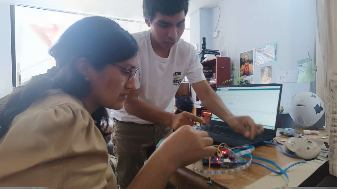
Program interaction between sound input and visual output.
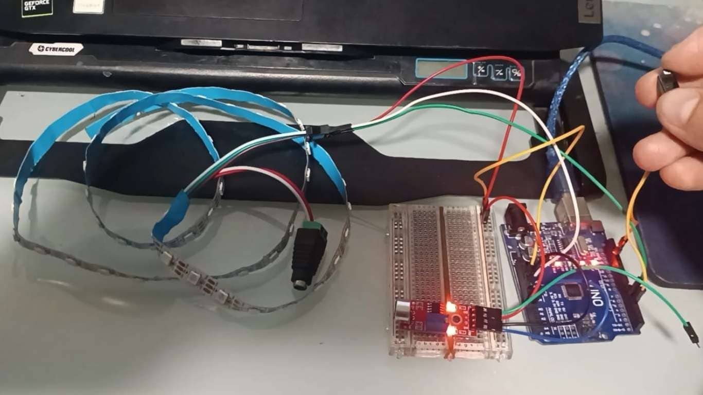
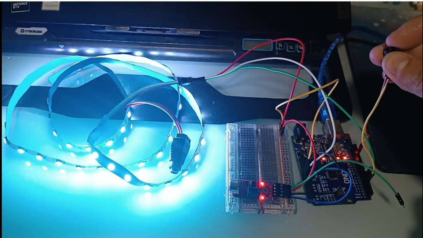
Tests were conducted to evaluate whether the KY-038 sound sensor could detect music and trigger movement in sync with the rhythm. Additionally, a switch was tested to confirm that it could successfully activate the system. Both tests were successful, though multiple adjustments and iterations were needed to fine-tune the sensor’s sensitivity and motor response.
Build physical structure
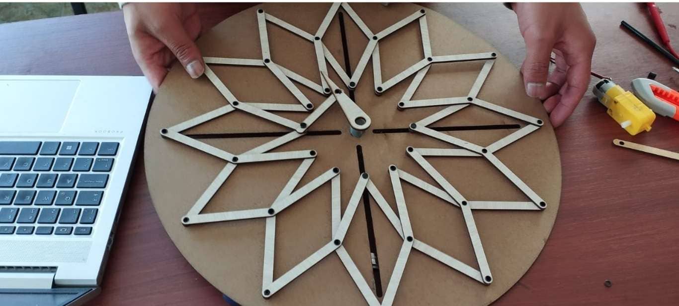
The mechanical design was relatively simple, but the challenging part was creating the joints so they would align properly with the circle. That process took a bit more time, but it was successfully achieved in the end.
Test motor performance and mechanical alignment.
-A code was developed to operate the mechanical part. The sensor responded correctly—it detected when a hand passed in front of it and immediately activated the motor, causing the joints to begin contracting and expanding.
            #include
                #include

                // Pines del sensor ultrasónico
                const int trigPin = 9;
                const int echoPin = 8;

                // Pines del motor (L298N)
                const int motorPWM = 5;
                const int motorDir = 7;

                // Pines de LEDs
                const int ledDetectado = 3;   // LED que se enciende cuando se detecta
                const int ledNoDetectado = 4; // LED que se enciende cuando no se detecta

                // Comunicación DFPlayer Mini
                SoftwareSerial mp3Serial(10, 11); // RX, TX
                DFRobotDFPlayerMini mp3;
                bool mp3Ready = false;

                void setup() {
                  Serial.begin(9600);
                  mp3Serial.begin(9600);

                  pinMode(trigPin, OUTPUT);
                  pinMode(echoPin, INPUT);
                  pinMode(motorPWM, OUTPUT);
                  pinMode(motorDir, OUTPUT);

                  // Pines LED
                  pinMode(ledDetectado, OUTPUT);
                  pinMode(ledNoDetectado, OUTPUT);

                  analogWrite(motorPWM, 0);
                  digitalWrite(motorDir, LOW);

                  Serial.println("Iniciando DFPlayer...");
                  if (mp3.begin(mp3Serial)) {
                    mp3.volume(25);
                    mp3Ready = true;
                    Serial.println("DFPlayer listo.");
                  } else {
                    Serial.println("DFPlayer no responde. Continuando sin sonido.");
                  }
                }

                void loop() {
                  // Medición ultrasónica
                  digitalWrite(trigPin, LOW);
                  delayMicroseconds(2);
                  digitalWrite(trigPin, HIGH);
                  delayMicroseconds(10);
                  digitalWrite(trigPin, LOW);

                  long duration = pulseIn(echoPin, HIGH);
                  float distance = duration * 0.034 / 2;

                  Serial.print("Distancia: ");
                  Serial.print(distance);
                  Serial.println(" cm");

                  if (distance > 0 && distance < 15) {
                    Serial.println("Objeto detectado. Encendiendo motor, LED y sonido.");

                    // Encender LED de detección, apagar el otro
                    digitalWrite(ledDetectado, HIGH);
                    digitalWrite(ledNoDetectado, LOW);


                    // Encender motor al 50%
                    digitalWrite(motorDir, HIGH);
                    analogWrite(motorPWM, 50);
                    delay(200);
                    analogWrite(motorPWM, 255);
                    Serial.println("Motor apagado.");

                    delay(1000); // Pausa para evitar repeticiones rápidas
                  } else {
                    // Si no se detecta, encender LED de no detección
                    digitalWrite(ledDetectado, LOW);
                    digitalWrite(ledNoDetectado, HIGH);
                  }

                  delay(200);
                }
With the HC-SR04 ultrasonic sensor, we were able to carry out the necessary tests to make the structure contract and expand properly.
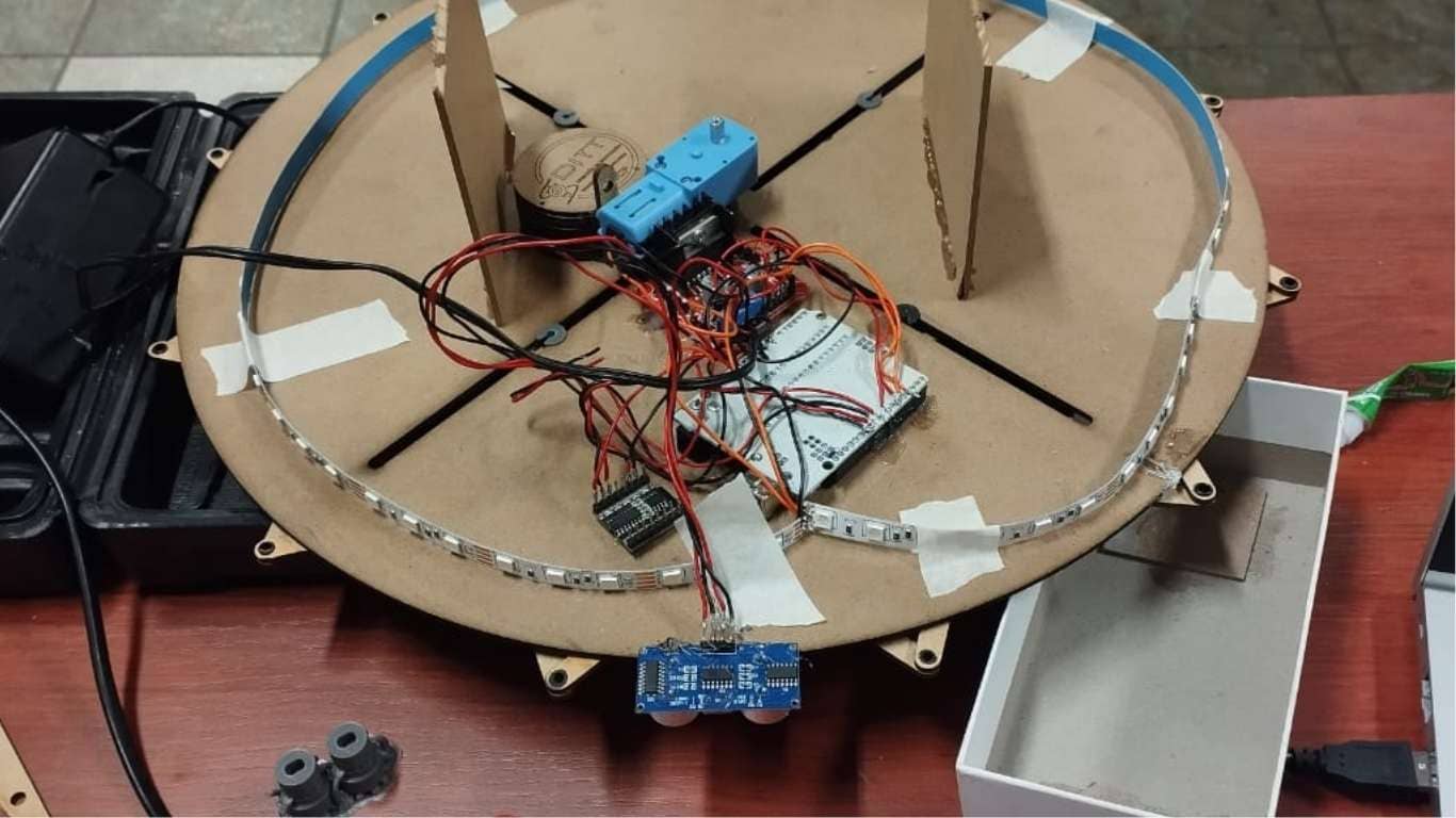
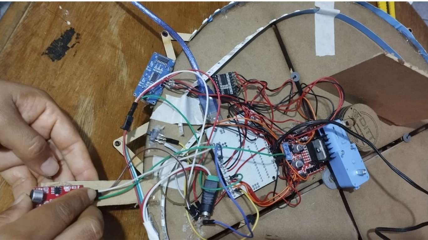
Here you can see the connections that were made to ensure the motor functions properly.
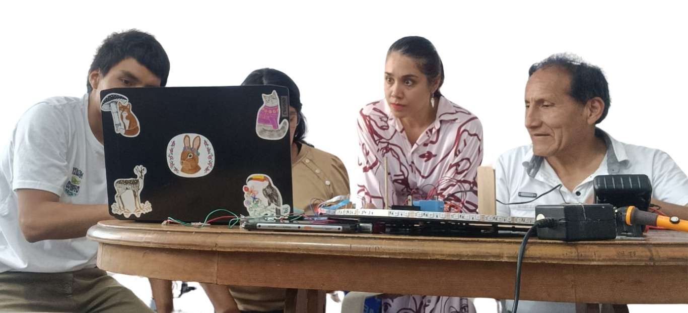
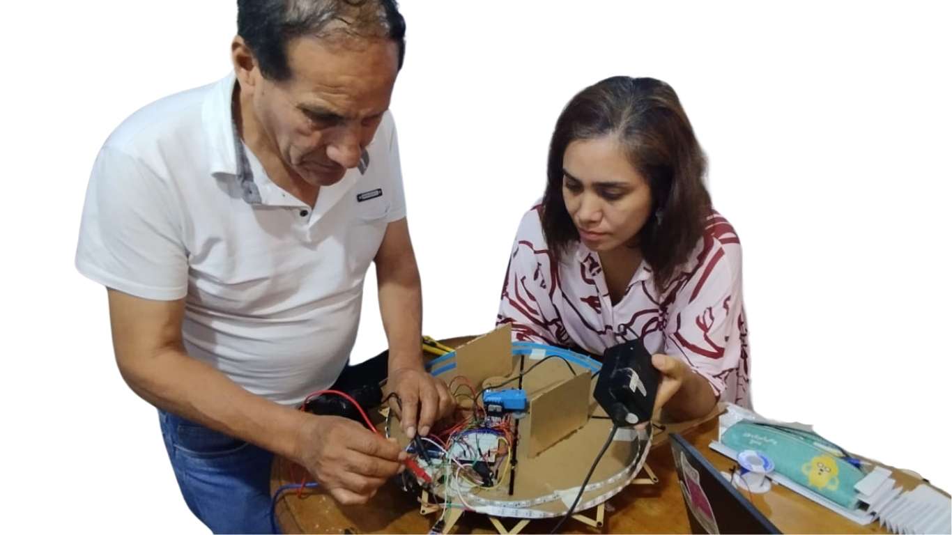
To continue with the assembly process and put together the pieces we had been working on, Armando traveled to the city of Lima so we could meet. We gathered at his house, where we worked as a team to complete the group assignment and build our machine.
For this phase, Armando brought in his daughter, who is an electronics engineer Giuliana Calcina Damas, and his nephew, a mechatronics engineer Yhamil Favio Munive Calcina. Both were willing to support us in moving the project forward. It was a highly participatory and enriching experience; having two experts in the field was a great help for us.
They reviewed the code to ensure everything was correctly programmed and that the machine would function properly. Additionally, the motor’s power was reduced to prevent it from rotating too abruptly.
We began making the connections between the different parts of our work: the section developed by Armando and the one I worked on.
This step was crucial to properly integrate the components and ensure the system would function as a whole.
There were no issues integrating the two systems; everything worked well. However, we did encounter difficulties with the threshold, as it was not detecting the signal properly. To resolve this, we had to change some pins, which took time since identifying the issue was not straightforward.
Another challenge was the power supply. We needed more power for the machine to operate correctly, so we decided to use two sources: one connected to the main power along with a battery, and the other coming from the laptop. This solution helped the machine run smoothly.
            #include
                #include
                #include

                // Pines del sensor ultrasónico
                const int trigPin = 9;
                const int echoPin = 8;

                // Pines del motor (L298N)
                const int motorPWM = 5;
                const int motorDir = 7;

                // Pines de LEDs simples
                const int ledDetectado = 3;
                const int ledNoDetectado = 4;

                // Pines del micrófono y tira LED NeoPixel
                #define SOUND_SENSOR_PIN A0
                #define NEOPIXEL_PIN 6
                #define NUM_PIXELS 63
                #define SOUND_THRESHOLD 128

                // DFPlayer
                SoftwareSerial mp3Serial(10, 11); // RX, TX
                DFRobotDFPlayerMini mp3;
                bool mp3Ready = false;

                // NeoPixel
                Adafruit_NeoPixel strip(NUM_PIXELS, NEOPIXEL_PIN, NEO_GRB + NEO_KHZ800);

                // Control de tiempo
                unsigned long lastActivation = 0;
                unsigned long activationCooldown = 1000;

                void setup() {
                  Serial.begin(9600);
                  mp3Serial.begin(9600);

                  pinMode(trigPin, OUTPUT);
                  pinMode(echoPin, INPUT);
                  pinMode(motorPWM, OUTPUT);
                  pinMode(motorDir, OUTPUT);
                  analogWrite(motorPWM, 0);
                  digitalWrite(motorDir, LOW);

                  pinMode(ledDetectado, OUTPUT);
                  pinMode(ledNoDetectado, OUTPUT);

                  strip.begin();
                  strip.clear();
                  strip.show();

                  if (mp3.begin(mp3Serial)) {
                    mp3.volume(25);
                    mp3Ready = true;
                    Serial.println("DFPlayer listo.");
                  } else {
                    Serial.println("DFPlayer no responde.");
                  }

                  randomSeed(analogRead(0)); // Inicializar aleatoriedad
                }

                void loop() {
                  bool trigger = false;

                  // Sensor ultrasónico
                  digitalWrite(trigPin, LOW);
                  delayMicroseconds(2);
                  digitalWrite(trigPin, HIGH);
                  delayMicroseconds(10);
                  digitalWrite(trigPin, LOW);
                  long duration = pulseIn(echoPin, HIGH);
                  float distance = duration * 0.034 / 2;

                  if (distance > 0 && distance < 15) {
                    trigger = true;
                  }

                  // Sensor de micrófono
                  int soundLevel = analogRead(SOUND_SENSOR_PIN);
                  if (soundLevel > SOUND_THRESHOLD) {
                    trigger = true;
                  }

                  // Activación si alguno de los sensores se dispara
                  if (trigger && millis() - lastActivation > activationCooldown) {
                    lastActivation = millis();
                    activarSistema();
                  }

                  delay(50);
                }

                void activarSistema() {
                  Serial.println("Activación por sensor!");

                  // LEDs simples
                  digitalWrite(ledDetectado, HIGH);
                  digitalWrite(ledNoDetectado, LOW);

                  // Tira LED con color aleatorio
                  uint8_t r = random(50, 256);
                  uint8_t g = random(50, 256);
                  uint8_t b = random(50, 256);
                  for (int i = 0; i < NUM_PIXELS; i++) {
                    strip.setPixelColor(i, strip.Color(r, g, b));
                  }
                  strip.show();

                  // DFPlayer
                  if (mp3Ready) {
                    mp3.play(1);
                  }

                  // Motor
                  digitalWrite(motorDir, HIGH);
                  analogWrite(motorPWM, 100);
                  delay(200);
                  analogWrite(motorPWM, 255);

                  // Apagar después de 1 segundo
                  delay(1000);
                  strip.clear();
                  strip.show();
                  analogWrite(motorPWM, 0);
                  digitalWrite(ledDetectado, LOW);
                  digitalWrite(ledNoDetectado, HIGH);
                }
By integrating the electronic components and making the necessary adjustments to the code, as well as solving the power supply issues, we were able to get the sound machine working properly. The axes, motor, and electronic programming all functioned as intended, successfully meeting the project’s objectives.
Due to the limited time available to develop this machine, it is important to highlight some improvements that could be implemented in a future version:
Application: Transforming ideas generated by artificial intelligence into precise physical drawings, integrating automation, technological recycling, and creativity within the Industry 4.0 philosophy.
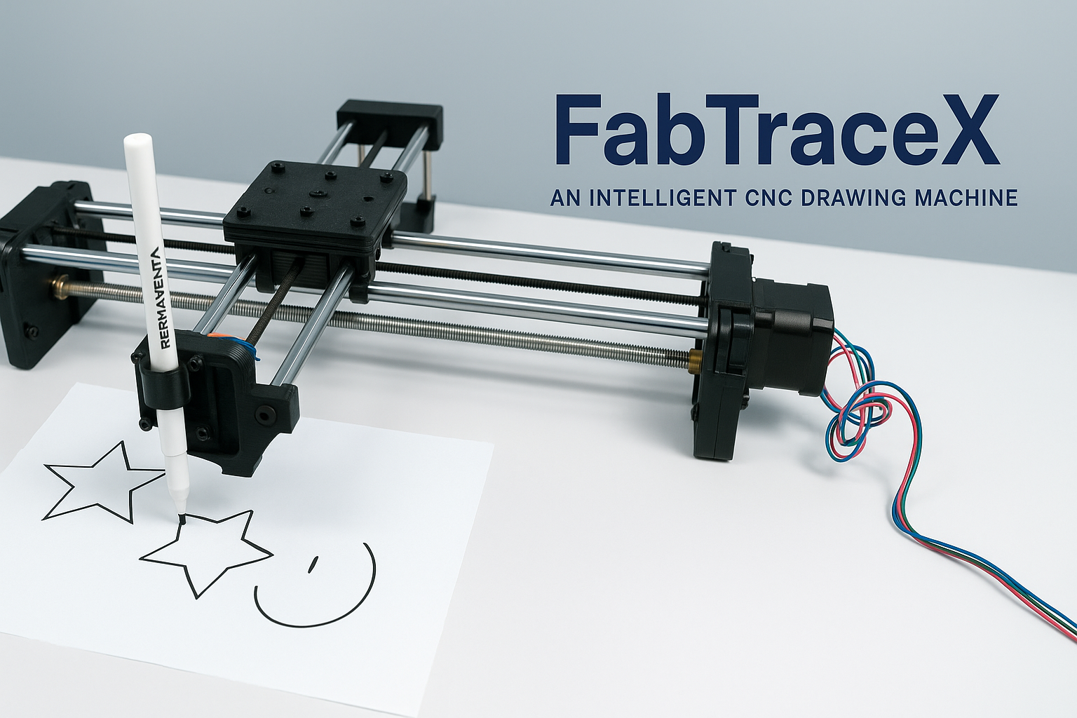
FabTraceX is born as an innovative proposal responding to the increasing interaction between artificial intelligence and physical machines. The idea arises with the purpose of reusing technological resources from EANLab, especially unused 3D printers, to build a CNC machine capable of automatically drawing images received from an AI API. This project combines mechanical design, automation, and practical application, within a sustainable approach.
The machine is a Cartesian CNC structure, including reused mechanical components such as stepper motors, linear rails, and structural bases. The first stage of development involves creating the mechanical elements and testing them manually. Subsequently, it progresses to automated actuation, where the machine can receive commands directly from AI, process them, and render graphics in real time.
FabTraceX is based on a Cartesian displacement system on two axes (X, Y), but with an innovative approach in its construction. It uses a single belt and two motors which, depending on the combination of rotation directions, allow precise control of the drawing arm's position on both axes. This simplified mechanical design seeks efficiency and reduced material use, leveraging recycled parts from 3D printers.
In its initial phase, the machine was manually operated and later integrated with stepper motors controlled by G-code. Currently, FabTraceX can already receive and execute programmed trajectories, enabling it to perform simple drawings generated directly from predefined code files.
Although full automation with AI integration is still under development, progress has been made in processing custom G-codes. The connection with AI APIs is in the design and testing phase, due to the time required for proper integration and training for effective image generation. This functionality is projected for future phases.
In its current form, FabTraceX can serve as an educational and experimental CNC platform, ideal for understanding the principles of controlled movement, G-code generation, and the basic operation of an automated machine. In the future, with AI integration, it is expected to create unique real-time drawings, transforming text or ideas into physical graphics autonomously.
FabTraceX aims not only to be an automated drawing machine but also a symbol of sustainable innovation. By recovering technological materials and giving them new life, it fits within the Industry 4.0 movement, where artificial intelligence, automation, and sustainability converge. It is an ideal platform to explore how machines can "think and create", powered by AI algorithms but also by the creative minds of its users.
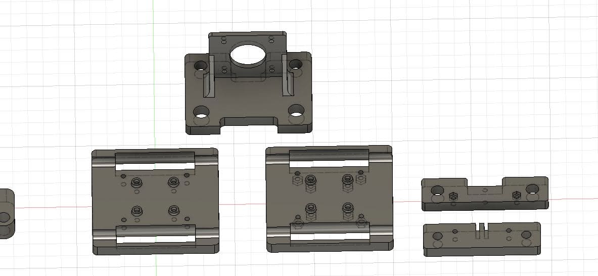
To bring FabTraceX to life, the team began by dismantling obsolete 3D printers to recover reusable components. During this process, many parts were found to be incompatible with standard models, which led the group to completely redesign several mechanical elements using Fusion 360.
This stage was essential, and the entire team collaborated on correcting and adjusting designs, ensuring that the parts fit properly and the mechanical structure was functional and stable.
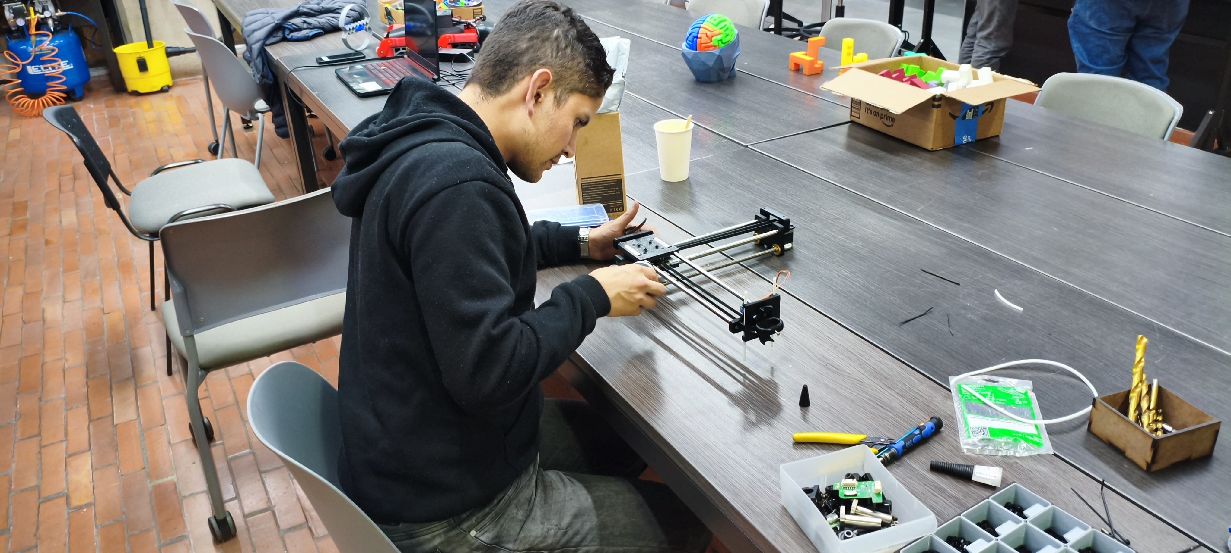
With the structure defined, the team proceeded to:
Thanks to this collaborative effort, a fully functional mechanical system was achieved, ready for automation.
An ESP32 was configured with FluidNC 3.8.3 firmware, enabling Wi-Fi connectivity. A custom configuration was uploaded, defining movement limits, axis parameters, and motor setups. Initially, DRV8825 drivers were used, but due to stability issues, the team switched to A4988 drivers, achieving more reliable control. All electronic connections were assembled on a breadboard, allowing easy testing and adjustments.
ChatGPT was used to manually generate G-code, such as a five-pointed star. The code was saved in
.gcode format and executed using Candle.
The ESP32 processed these instructions, sending them to the stepper motors, allowing the
machine to perform simple drawings accurately.
The team conducted exploratory tests with different artificial intelligence models:
These tests helped identify the technical challenges for future AI integration.
Although AI integration is still under development, FabTraceX can already execute drawings through manual G-code, proving its viability as an automated creation platform.
Next Steps:
Team: Manuel Ayala-Chauvin, Sandra Nuñez-Torres
Institution: Fablab - Universidad Tecnológica Indoamérica
Year: 2025
This project aimed to design, build, and automate a low-cost CNC milling machine equipped with a continuity sensor to map surface profiles on copper plates. By applying a concurrent engineering approach, the team simultaneously developed the mechanical, electronic, and software systems to achieve a modular, affordable, and replicable machine for educational and research environments.
The machine was conceived as a three-axis Cartesian CNC with a leadscrew drive system, capable of manual and automated operation. The design prioritized low-cost materials, ease of fabrication, modularity for future upgrades, and sufficient precision for contour line generation.
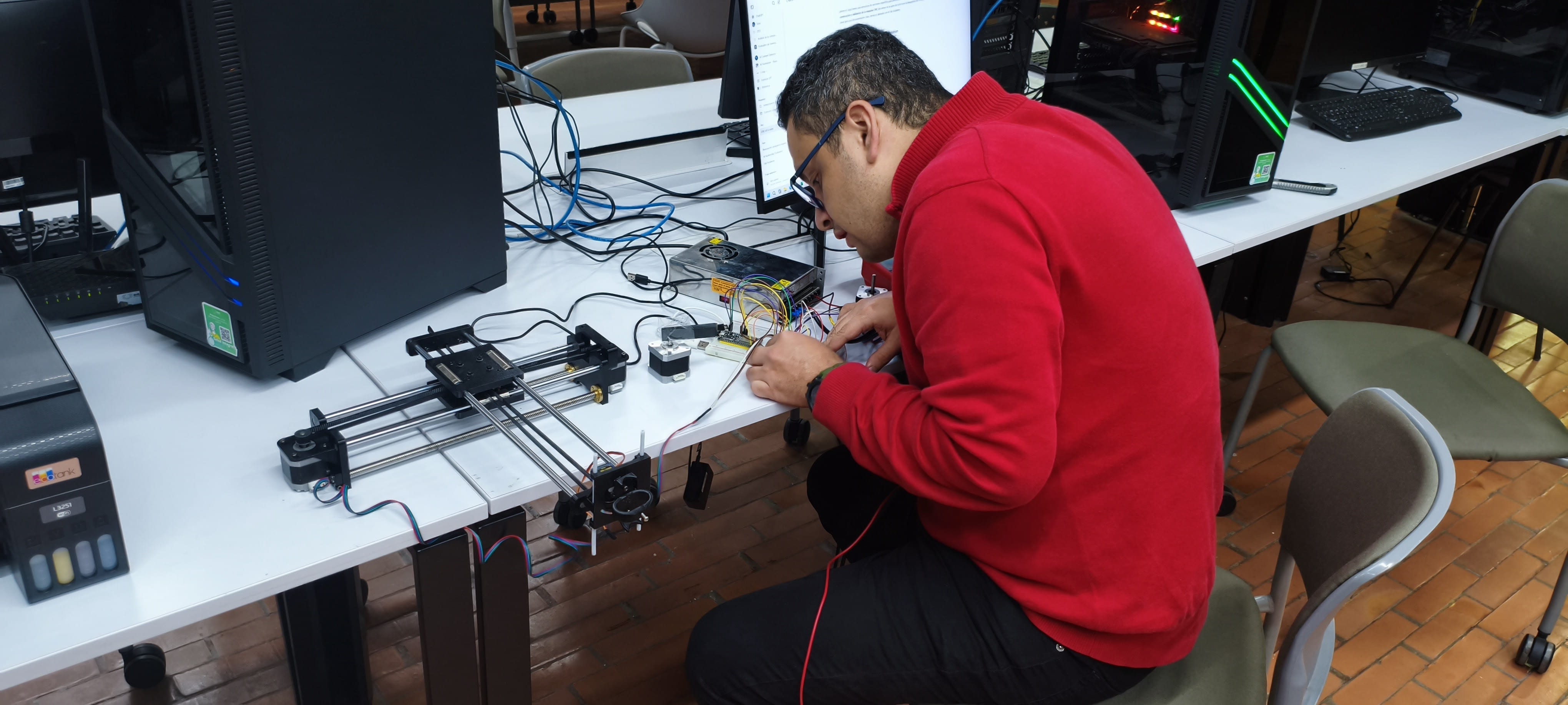
The frame was built using aluminum profiles and AISI 1020 steel reinforcements. Movement was guided by linear rails (12 mm) and driven by 8 mm leadscrews with a 2 mm pitch. Before installing electronics, the machine was manually operated via hand cranks to validate mechanical alignment, smoothness of motion, and structural rigidity. FEA simulations predicted a maximum displacement of 0.0236 mm under load, which manual testing later confirmed as acceptable.
The mechanical design was based on a four-stage method:
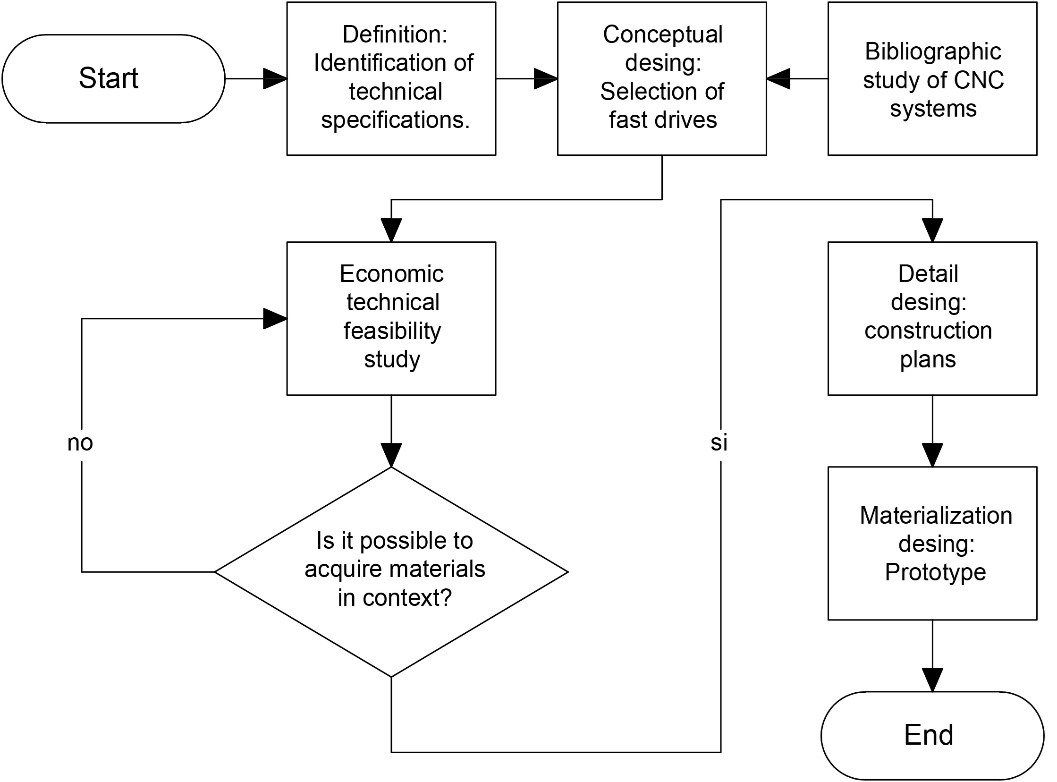
The diagram presents the systematic design process used for the low-cost CNC milling machine project. It begins with the identification of technical specifications, which define the project's fundamental requirements such as work area dimensions, desired precision, and operational capacity. The next step involves conceptual design, focusing on selecting suitable motion systems like leadscrews and motors. A bibliographic study of existing CNC technologies is conducted in parallel to enrich the conceptual framework. Once the preliminary design is ready, a technical and economic feasibility study is carried out to evaluate material availability and budget constraints. If materials are not obtainable within the project’s context, the process loops back to redefine specifications and adjust the design accordingly. When feasibility is confirmed, the project advances to the detailed design phase, generating complete CAD models, technical drawings, and part lists. The final stage is the materialization phase, where the prototype is constructed based on the finalized plans. This iterative and feedback-driven process ensures the CNC machine is not only functional and efficient but also economically viable and adaptable to local fabrication capabilities.
As the mechanical design leader, Manuel was responsible for creating detailed three-dimensional CAD models of the entire CNC milling machine using SolidWorks. This work included modeling the primary structure (frames and supports), the motion transmission system (leadscrews, couplings, linear guides), and the mechanical subassemblies (motor mounts, sensor holders, spindle supports). Each component was designed parametrically to allow for easy adjustments and scalability. The modeling process ensured that interferences were minimized, tolerances were respected, and that future modifications, such as enlarging the working area or integrating new actuators, could be accomplished efficiently. Additionally, the CAD models served as the basis for generating technical drawings for fabrication and assembly documentation.
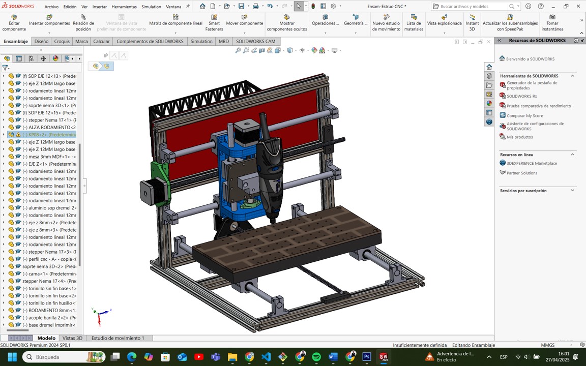
This screenshot shows the complete CAD model of the machine developed in SolidWorks. The left sidebar lists each component and subassembly, such as motors, rods, and bearings. It demonstrates that the project followed good parametric modeling practices, ensuring easy modifications or scaling of the machine. The final 3D design confirms that all motion systems are correctly aligned and mechanically feasible.
Manuel conducted comprehensive mechanical analyses to determine the necessary force and torque requirements for each axis movement. Using basic dynamic and static formulas, he calculated the load requirements based on the weight of moving elements, friction coefficients, and desired acceleration values. Based on these calculations:
After the fabrication of individual parts, Manuel personally led the mechanical assembly of the CNC machine. This process required careful squaring and alignment of the frame, precision positioning of the linear rails, and exact installation of leadscrews and bearings. Mechanical calibration was critical: each axis was manually moved and adjusted to eliminate excessive friction, misalignment, or backlash. Dial indicators, calipers, and alignment jigs were used to validate and correct the mechanical setup, ensuring smooth and accurate movement across all three axes (X, Y, and Z). These manual efforts directly contributed to the machine’s final precision during both manual and automated operations.
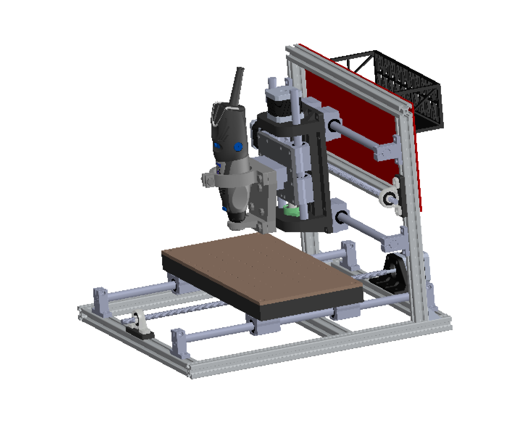
This image displays the fully assembled CNC milling machine ready for operation. It highlights the Dremel spindle mounted correctly, the bed aligned with X and Y axis movement, and the general structural stability of the design. The aluminum and steel frame ensures a balance between weight and rigidity, vital for precision scanning and machining tasks.
One of the fundamental contributions was the design of the external structural elements that house and protect the CNC milling machine’s functional components. This included the development of an ergonomic and protective outer shell that minimizes external particle ingress, improves user safety, and optimizes aesthetics. Operator interfaces, such as emergency stop locations, manual access points for tool changes, and the positioning of control buttons, were carefully analyzed and incorporated. Additionally, the red rear protection panel was strategically designed not only to shield sensitive components but also to serve as a mounting platform for cable management and future electronics (controllers, sensors). The entire layout was modeled in SolidWorks to ensure seamless integration with the mechanical motion system without causing interferences.
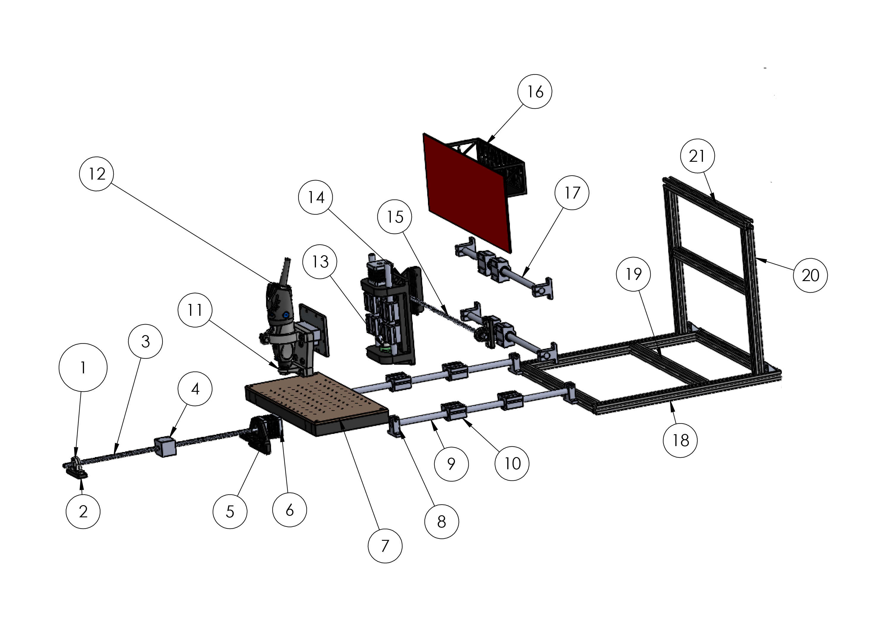
This image shows an exploded view of the CNC milling machine, where each component is separated to visualize its positioning and assembly order. Key elements include the linear rails (8 and 9), leadscrews (1 and 5), spindle mount (11), rear frame (20 and 21), and the protective electronics panel (16). This view is essential to understand how parts fit together and how to proceed during assembly or maintenance.
Prior to the automation phase, manual validation of the CNC machine was critical. Sandra conducted a series of usability inspections to confirm that operators could comfortably access critical areas such as: - The spindle head (for tool attachment and maintenance), - The bed surface (for part loading and securing), - Leadscrew supports and guide rails (for maintenance and alignment verification). Adjustments were proposed and implemented, such as slight repositioning of the bed relative to the frame and additional clearances in the Z-axis structure, to enhance ease of use without compromising mechanical performance. These actions directly contributed to reducing setup and maintenance times, improving the overall machine usability.
A systematic usability testing protocol was developed, involving practical walkthroughs of typical machine operations in a manual mode. Sandra documented ergonomic bottlenecks, safety hazards, and operator fatigue risks. Recommendations arising from this testing included: - The placement of cable routing away from operator access paths, - The suggestion of installing a transparent protective screen for moving parts, - Guidelines for labeling manual control interfaces clearly. These improvements were integrated into the second mechanical validation cycle and contributed substantially to enhancing the machine’s operational experience, particularly for new or non-expert users. All findings were archived in the project’s design documentation to inform future iterations or scalability projects.
The machine was automated by integrating three NEMA 17 stepper motors driven by DRV8825 drivers, controlled through an Arduino UNO with a CNC Shield. A fine-contact continuity sensor was connected to detect surface variations along the Z-axis. Toolpaths were generated using Vectric Aspire and executed with Universal G-Code Sender.
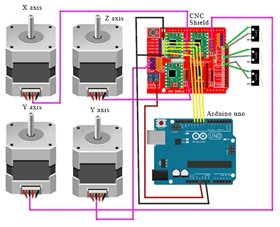
The image illustrates the electronic control system architecture implemented for the low-cost CNC milling machine. At the center of the system is an Arduino UNO, which serves as the main microcontroller, responsible for interpreting G-code commands and translating them into precise motion instructions. Mounted on top of the Arduino is a CNC Shield, which organizes and routes the electrical connections to the stepper motor drivers and limit switches. Four NEMA 17 stepper motors are connected: one motor controls the X-axis movement, one controls the Z-axis vertical movement, and two motors are connected to the Y-axis to ensure synchronized and stable motion of the machine bed. Each motor is powered and driven independently through the CNC Shield, allowing fine control over direction and steps. This modular setup ensures that the CNC machine can achieve high precision while maintaining a low-cost, open-source hardware base. The use of a CNC Shield simplifies wiring complexity and enhances system maintainability, making the machine more accessible to students, researchers, and DIY makers. Furthermore, the dual-motor configuration on the Y-axis significantly improves structural stability and alignment during fast movements, which is critical for maintaining milling accuracy. Overall, this configuration represents an efficient, scalable, and easily replicable solution for educational and small-scale manufacturing environments.
The automated system was tested over copper plates to verify contour mapping accuracy. Calibration of stepper motor steps/mm and sensor response ensured consistent scanning performance.
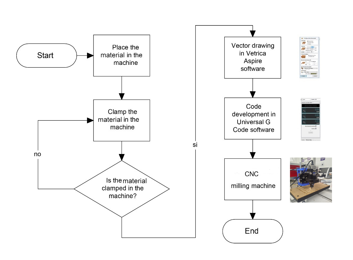
The figure shows the workflow used to machine any type of material on the low-cost CNC milling machine. The process begins by placing the material inside the machine and securely clamping it using holding systems. If the material is not properly fixed, adjustments must be made to ensure a firm hold, essential to prevent displacement during machining. Once secure clamping is verified, the toolpath is designed using Vectric Aspire software, where the cutting paths are defined. Subsequently, the vector design is converted into G-code using Universal G-Code Sender software, setting the movement parameters for the axes. Finally, the CNC machine automatically performs the machining operation on the secured material. This workflow ensures that all steps, from material preparation to final machining, are performed in a controlled and precise manner, guaranteeing high-quality results.
The image shows the CNC milling machine connected to a laptop controlling the machining process via CAM software. The CNC setup is ready to execute the loaded machining program.
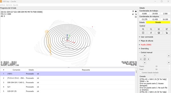
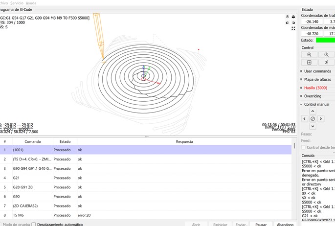
This screenshot displays the programmed toolpaths in a spiral pattern. G-code commands are successfully processed, with X, Y, and Z axes settings visible, ensuring that the machine is ready for precise operation.
A detailed view of the G-code console shows each processed command. While most commands are confirmed as "ok", some errors such as error20 (tool change) are noted, demonstrating real-time system feedback.
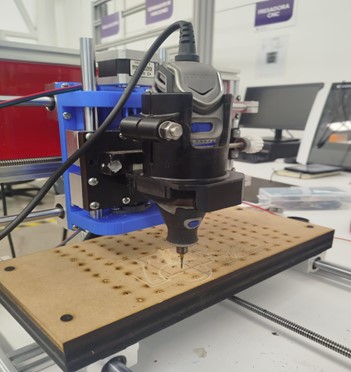
A close-up image of the milling machine engraving a circular path onto an MDF sheet. The tool is visibly executing the programmed path, confirming correct translation from digital to physical.
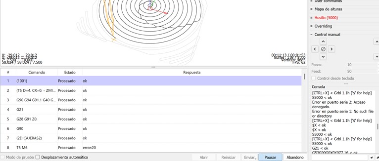
This image shows the active execution of the machining process with live tracking of tool movements and processed commands, confirming real-time system monitoring.
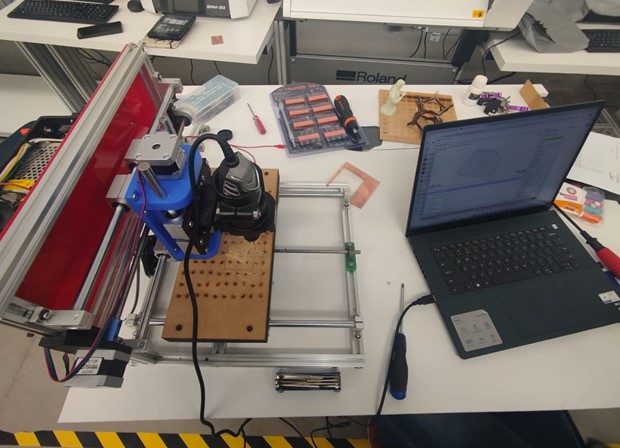
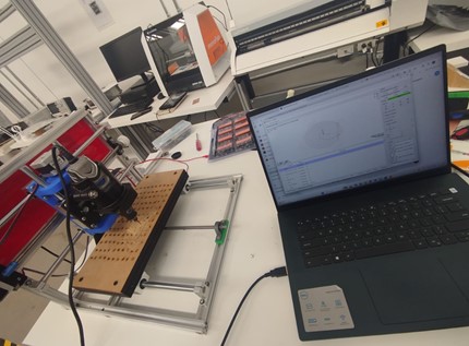
A top view of the complete CNC workstation, including the machine, laptop, tools, and materials. This setup highlights the comprehensive preparation for digital fabrication operations.
| Component | Cost (USD) |
|---|---|
| Stepper Motors (3 units) | $60 |
| Mechanical Components (guides, bearings, leadscrews) | $199 |
| Electronic Components (Arduino, Shield, Drivers) | $198 |
| Spindle (Dremel Tool) | $150 |
| Fabrication Labor and Assembly | $400 |
| Total | $1007 |
Notes: Bulk material sourcing could reduce overall costs by 10-15%.
Watch the video of operational testing here: https://youtu.be/TLGdXZf97eM
This project successfully demonstrated the viability of designing and constructing a low-cost CNC milling machine for contour mapping applications. Through meticulous mechanical design, careful component selection, and synchronized software development, a highly functional and accessible machine was built.
The collaboration between mechanical design and usability specialists ensured that both technical performance and user experience were addressed from the earliest stages. Future improvements will explore higher resolution sensing, faster scanning speeds, and extended machining capabilities.
During Week 12, we successfully applied the complete cycle of mechanical and machine design principles to create a functional, low-cost CNC milling machine capable of surface scanning and material machining. The collaborative effort between mechanical structure development, electronics integration, and usability validation allowed us to build a robust and replicable system. By following concurrent engineering practices, we shortened development time, reduced iteration errors, and achieved a high level of integration across mechanical and electronic subsystems. The experience emphasized the critical importance of interdisciplinary collaboration, early validation through manual operation, and structured design methodologies. This project not only strengthened our technical skills in CAD modeling, dynamics calculations, electronics programming, and CNC automation but also reinforced key soft skills such as teamwork, documentation, and project planning. Moving forward, we aim to refine the system with higher precision sensors, improved control interfaces, and expanded machining capabilities for broader applications.
Click the button below to access and download all available materials.
Download Resources