- Document your individual contribution
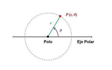
Rectangular and Polar Coordinates
This task aims to materialize the development of a project that can move along rectangular coordinate axes (x, y) or polar coordinates (r, 0). That is, it can drive elements that move along these axes. This could be a machine or mechanism that performs an automated function. Therefore, we began with the idea of creating a machine that we will call "VibroBot: a sound-powered kinetic machine."
Project Concept: "VibroBot: A Sound-Powered Kinetic Machine"
In this phase, I previously reviewed information from the state-of-the-art documentation on the Fab Academy website and analyzed several previous projects. This process allowed me to gather ideas, identify possibilities, and develop a clear understanding of the mechanism to be designed, especially one that meets the characteristics of movement in a rectangular and polar coordinate system—that is, to design a machine that integrates movement, art, and technology. For this reason, my project would now be called "VibroBot: A Sound-Powered Kinetic Machine".
Design stage
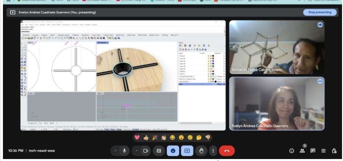
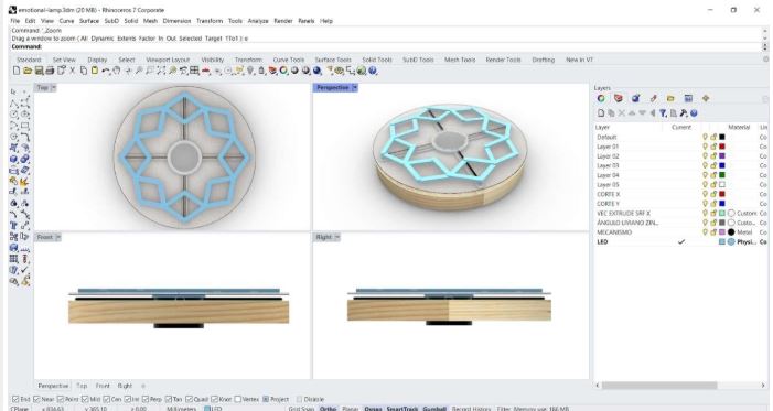
At this stage, with our classmate Evelyn, we designed a preliminary model of the machine, essential for visualizing the general structure of the machine and anticipating how its different parts would interact.
Review of the preliminary project
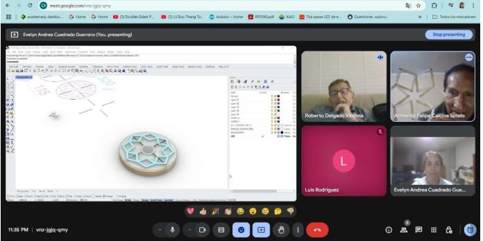
Afterward, Evelyn, Roberto, and I met to review the preliminary design of our machine to ensure we were aligned with the overall project concept. Once everything was clear, the final design was completed, and the entire mechanical structure of our machine was built.
1.-Design and Construction
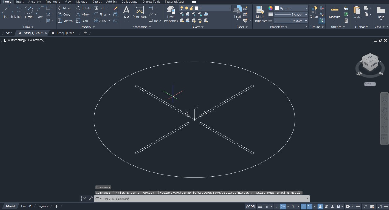
Base Design
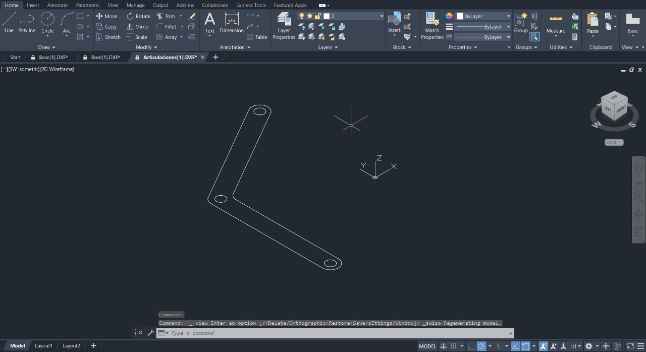
For the design of the base we have used AutoCAD software,To create the dimensions and slots on the x and y axes, which will house the connecting pins of the link joints, which will move on the x and y axes by means of the rotation of a clockwise link.
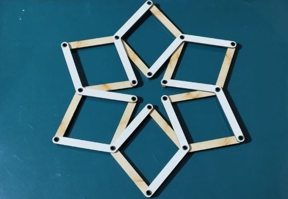
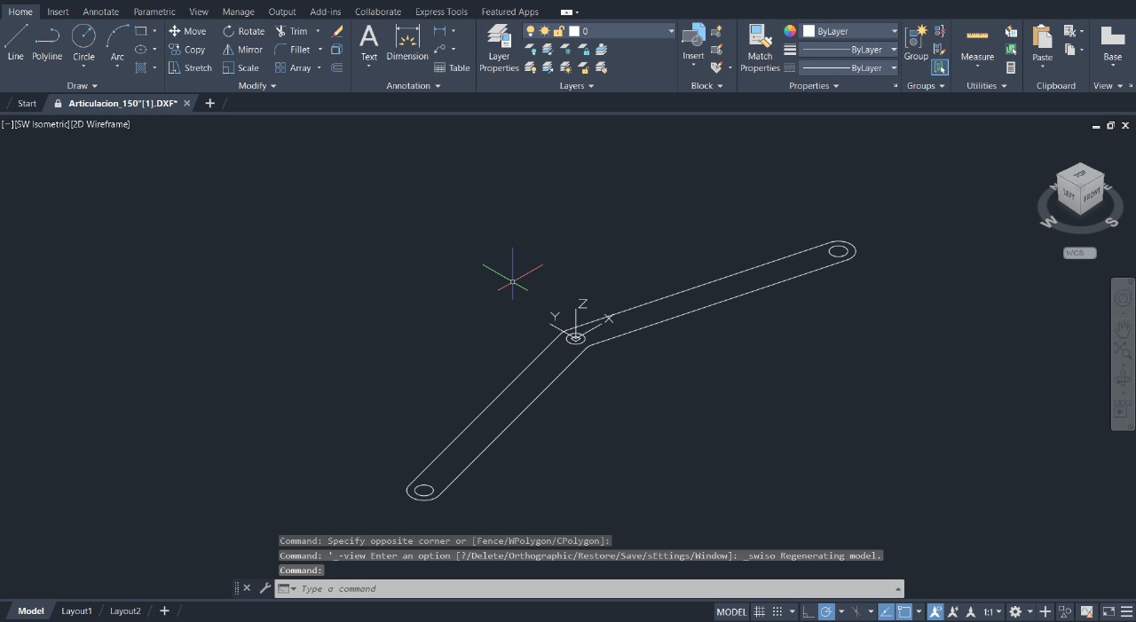
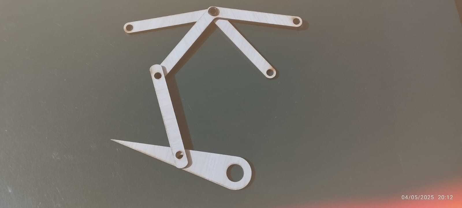
150-Degree Articulation Join
The mechanical components, which are links with obtuse angles of 150 degrees, will allow rotational movement of up to 150 degrees, in a total of 17 links.
Design in Autocad
The other component is also the design of a link with a 120° angle to form the geometric figures of a rhombus that can be opened and closed when the central element rotates, driven by the motor.
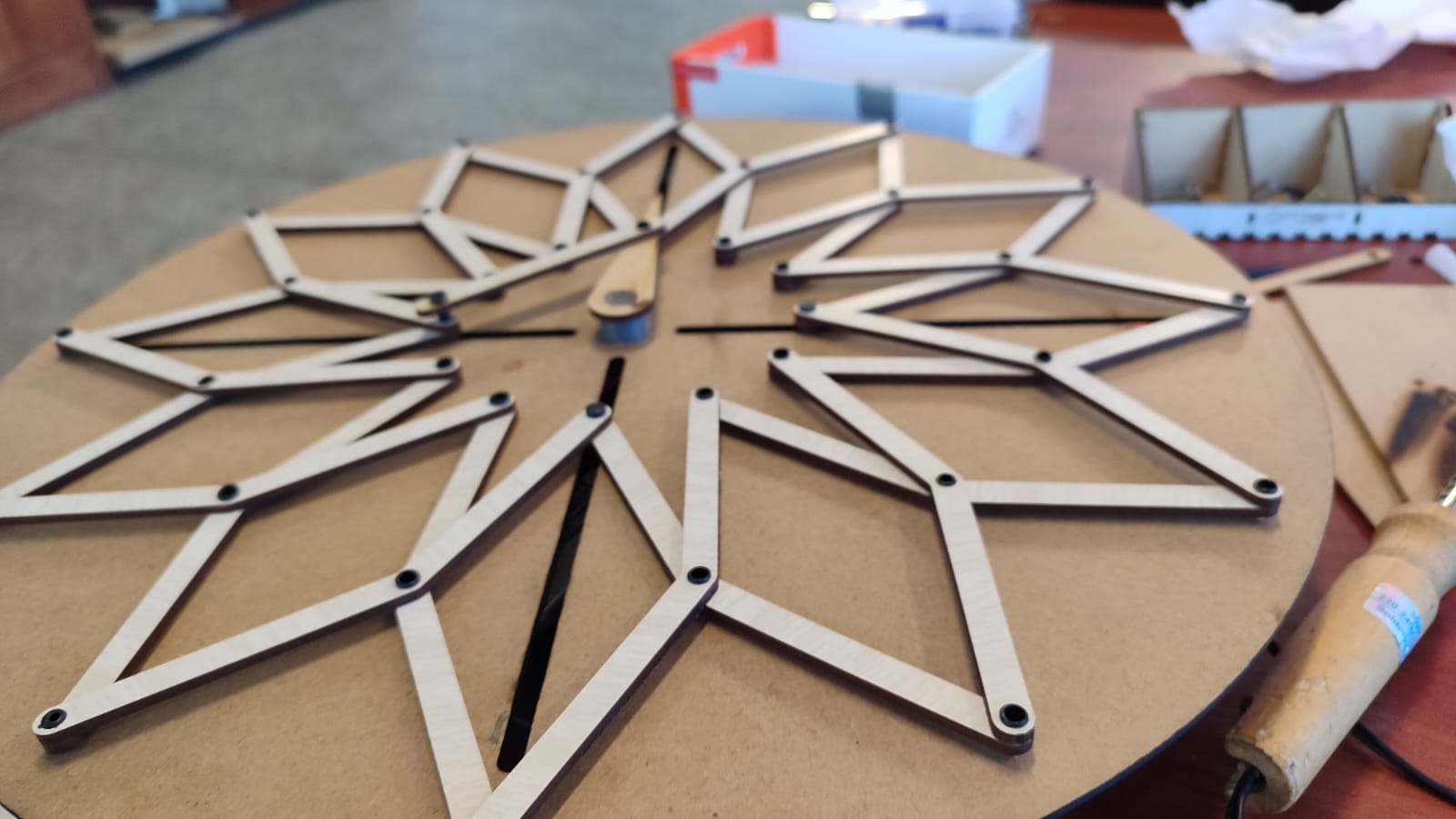
cutting parts
Using a CNC laser machine, all the pieces designed in AutoCAD software were cut, and then the pieces were assembled and joined together.
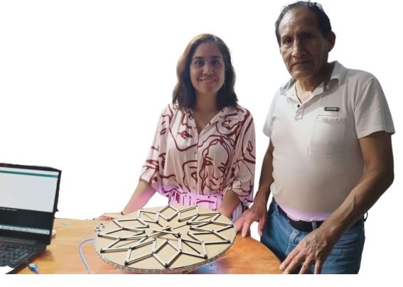
Construction
To build the machine, we started by joining all the parts together. We also used sliding spacers that would be placed at the joints, which would perform the sliding function when the motor and shaft mechanism rotate according to the rotation speed.
Once the components are ready, we begin making the connections according to our schematic diagram, and then continue with the programming in the auduino IDE environment.
2.-List of Components
The electronic components I will use for the project include an Arduino board, a 3- to 6-volt DC gear motor, an ultrasonic sensor, and a driver for powering and controlling the motor switch. These elements form part of the vibrobot's electronic mechanism and control, and will later be integrated into the program development and the machine's interaction with its environment
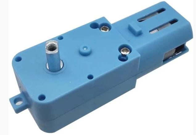
DC 3-6V gear motor
- Supply voltage: 3-6V
- Reduction: 48:1
- Load current consumption: 150mA
- Shaft diameter: 6mm
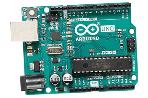
Arduino Uno
- Microcontroller: ATmega328P
- Operating Voltage: 5V
- Input Voltage (recommended): 7–12V
- Input Voltage (limit): 6–20V
- Digital I/O Pins: 14 (6 PWM outputs)
- Analog Input Pins: 6
- DC Current per I/O Pin: 20 mA
- Flash Memory: 32 KB (0.5 KB used by bootloader)
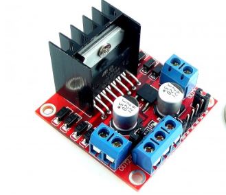
Driver L298N
- Motor operating voltage: 5V to 35V
- Logic voltage: 5V
- Maximum current: 2A per channel (3A peak)
- Channels: 2 (can control 2 DC motors or 1 stepper motor)
- Maximum PWM frequency: 40 kHz
- Thermal protection: Yes
- Integrated 5V voltage regulator (can be enabled or disabled via jumper)
3.-Electronic Programming in Arduino IDE
Once the components are ready, we begin making the connections according to our schematic diagram, and then continue with the programming in the auduino IDE environment.
- Arduino: Main controller that makes decisions and executes actions.
- Ultrasonic Sensor (HC-SR04): Measures the distance to an object using ultrasonic pulses.
- L298N Motor Driver: Controls the DC motor (speed and direction), since the Arduino cannot provide enough current directly.
- DC Motor: Activates when an object is detected.
Programming Code
#include
#include

// Pines del sensor ultrasónico
const int trigPin = 9;
const int echoPin = 8;

// Pines del motor (L298N)
const int motorPWM = 5;
const int motorDir = 7;

// Pines de LEDs
const int ledDetectado = 3;   // LED que se enciende cuando se detecta
const int ledNoDetectado = 4; // LED que se enciende cuando no se detecta

// Comunicación DFPlayer Mini
SoftwareSerial mp3Serial(10, 11); // RX, TX
DFRobotDFPlayerMini mp3;
bool mp3Ready = false;

void setup() {
  Serial.begin(9600);
  mp3Serial.begin(9600);

  pinMode(trigPin, OUTPUT);
  pinMode(echoPin, INPUT);
  pinMode(motorPWM, OUTPUT);
  pinMode(motorDir, OUTPUT);

  // Pines LED
  pinMode(ledDetectado, OUTPUT);
  pinMode(ledNoDetectado, OUTPUT);

  analogWrite(motorPWM, 0);
  digitalWrite(motorDir, LOW);

  Serial.println("Iniciando DFPlayer...");
  if (mp3.begin(mp3Serial)) {
  mp3.volume(25);
  mp3Ready = true;
Serial.println("DFPlayer listo.");
  } else {
Serial.println("DFPlayer no responde. Continuando sin sonido.");
  }
}

void loop() {
  // Medición ultrasónica
  digitalWrite(trigPin, LOW);
  delayMicroseconds(2);
  digitalWrite(trigPin, HIGH);
  delayMicroseconds(10);
  digitalWrite(trigPin, LOW);

  long duration = pulseIn(echoPin, HIGH);
  float distance = duration * 0.034 / 2;

  Serial.print("Distancia: ");
  Serial.print(distance);
  Serial.println(" cm");

 if (distance > 0 && distance < 15) {
	Serial.println("Objeto detectado. Encendiendo motor, LED y sonido.");

	// Encender LED de detección, apagar el otro
	digitalWrite(ledDetectado, HIGH);
	digitalWrite(ledNoDetectado, LOW);


	// Encender motor al 50%
	digitalWrite(motorDir, HIGH);
	analogWrite(motorPWM, 150);
	delay(400);
	analogWrite(motorPWM, 255);
	Serial.println("Motor apagado.");

	delay(1000); // Pausa para evitar repeticiones rápidas
  } else {
	// Si no se detecta, encender LED de no detección
	digitalWrite(ledDetectado, LOW);
	digitalWrite(ledNoDetectado, HIGH);
  }

  delay(200);
}
4.-mechanical design completed
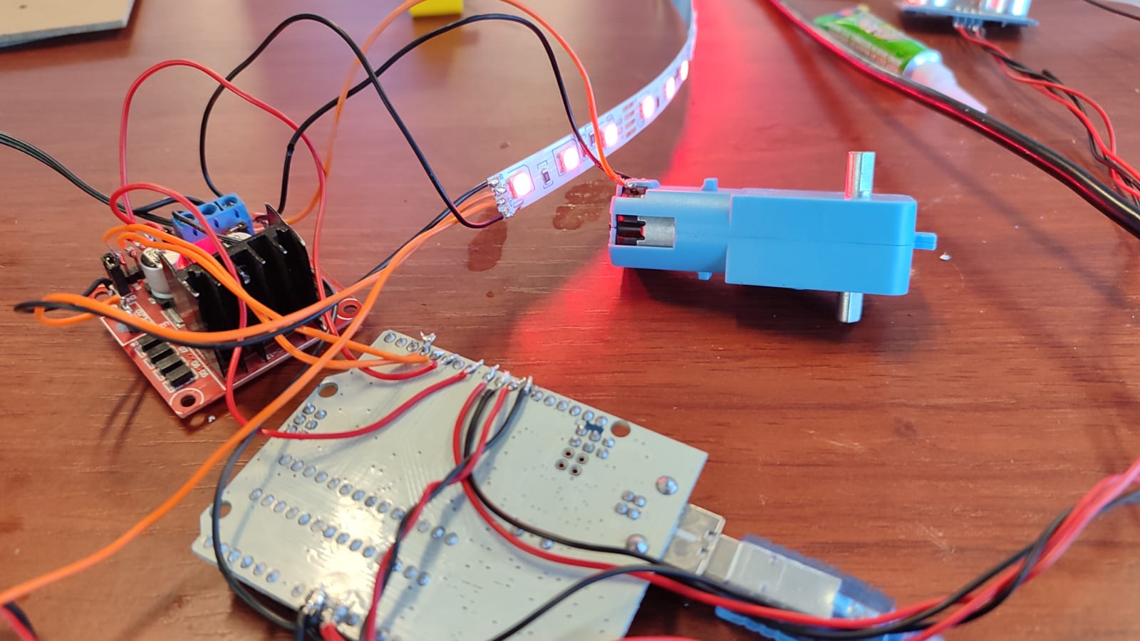
Several tests were performed to verify that the mechanism was working correctly and responding according to the programming code. However, we did have some issues with the power supply. We needed more power for the machine to function properly, so we decided to use two sources: one connected to the mains with a battery and the other from the laptop. This solution facilitated the machine's operation.
and we continue to perform tests to verify that everything is working correctly.
Below is the completed, assembled design. We see that the ultrasound sensor detects distance. If it is less than 15 cm, it turns on a detection LED, then activates the motor connected to the L298N (first at 50%, then briefly at 100%).