Week 12
Mechanical Design & Machine Design
Week Overview
This week focuses on mechanical design and machine building, where we collectively design a machine as a group and document the mechanical structure, individual responsibilities, assembly process, and learnings.
Electronics and Control System
This section documents the electronic design, wiring, and implementation of the control system for the machine. The process included the selection of the development board, motor driver, and stepper motor, as well as the definition of the power and connection scheme to integrate the electronic components into the mechanical structure.
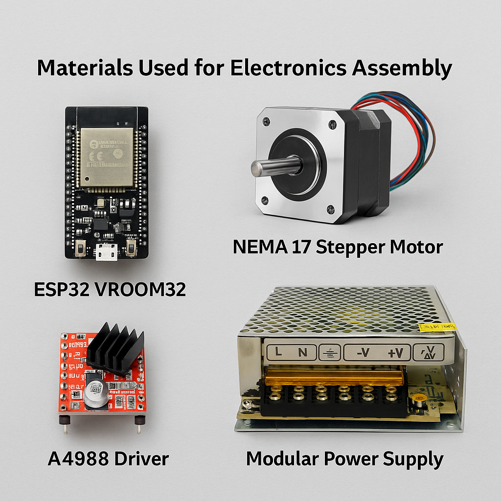
Materials Used for Electronics Assembly
For the electronics of our XY drawing machine, I selected and assembled the following components. These were essential for enabling motor control, powering the system, and processing G-code instructions from the computer.
| Item | Description | Purpose |
|---|---|---|
| ESP32 VROOM32 | Wi-Fi and Bluetooth-enabled microcontroller | Used as the main controller to receive and execute G-code via FluidNC |
| NEMA 17 Stepper Motor | 1.8° step angle, bipolar stepper motor | Drives the motion of the machine's X and Y axes |
| A4988 Driver | Stepper motor driver module | Controls step signals and current to the NEMA motor |
| Modular Power Supply | 12V / 30A regulated switching power supply | Provides reliable power to the driver and stepper motor |
The following image displays the main components I used for the electronic setup of our machine. These include the ESP32 VROOM32 microcontroller, a NEMA 17 stepper motor, an A4988 motor driver, and a modular 12V 30A power supply. These elements were crucial to ensure accurate motor control and stable operation of the system.
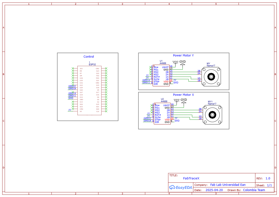
The schematic below illustrates the wiring setup for the electronic system of our machine. It shows the correct connections between the ESP32 VROOM32, A4988 drivers, the NEMA 17 stepper motors, and the 12V 30A power supply. These connections were carefully planned to ensure reliable motor operation and power management.
Connection Table for A4988 Drivers and ESP32 VROOM32
| Driver Pin | Connection Description | ESP32/GND/Power Pin | Notes |
|---|---|---|---|
| VMOT | Power supply for motor coils | 12V (Power Supply) | Shared for both drivers |
| GND (VMOT side) | Ground for motor power | GND (Power Supply) | Shared for both drivers |
| VDD | Logic power supply | 5V (ESP32) | Shared for both drivers |
| GND (Logic side) | Ground for logic | GND (ESP32) | Shared for both drivers |
| RESET | Reset control | 5V (ESP32) | Tied HIGH to enable operation |
| SLEEP | Sleep control | 5V (ESP32) | Tied HIGH to keep driver active |
| STEP | Step signal input | GPIO 25 | Controls movement on X axis |
| DIR | Direction control | GPIO 26 | Controls direction on X axis |
| STEP | Step signal input | GPIO 14 | Controls movement on Y axis |
| DIR | Direction control | GPIO 12 | Controls direction on Y axis |
Installing and Configuring FluidNC
After wiring all the electronic components, I proceeded to install FluidNC, an advanced firmware for ESP32 boards that allows direct control of CNC machines. This firmware offers high customization through YAML configuration files and allows wireless G-code streaming via Wi-Fi.
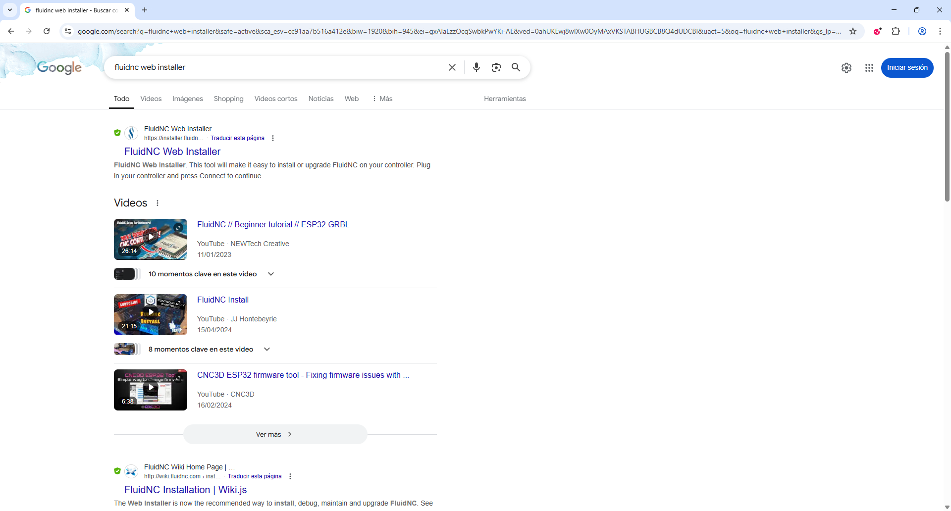
The first step is to search for "Fluid NC web installer" on Google and click on the first link.
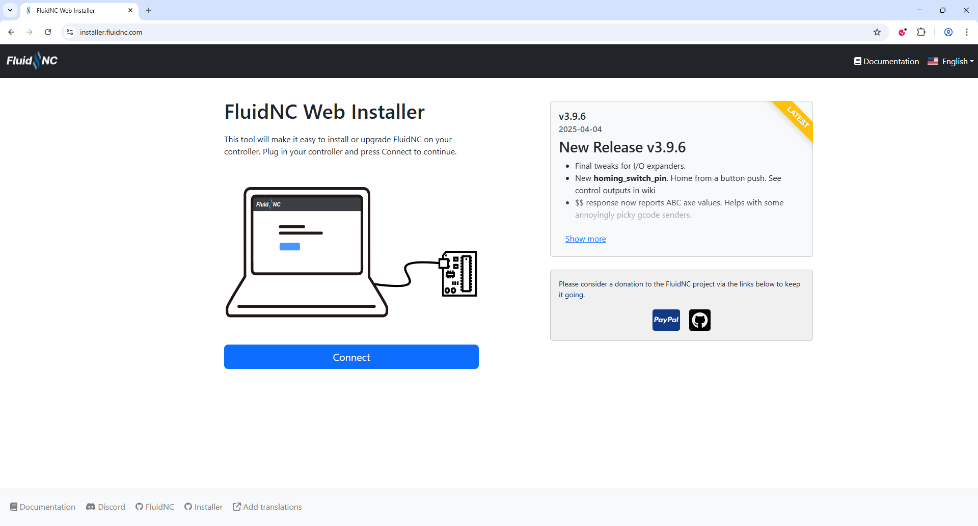
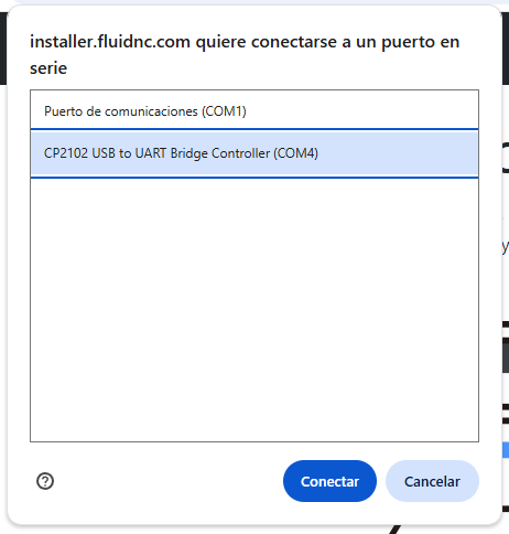
Then, you must click on "Connect". It's possible that the ESP32 won't be recognized immediately when connected to the computer, so it's important to make sure that the ESP32 is fully recognized and assigned to a COM port.
Select the corresponding port assigned to the ESP32 board. This ensures the installer can communicate correctly with the device.
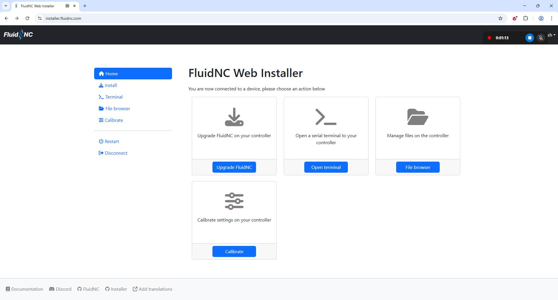
Once the ESP32 board is successfully connected, the following screen will appear. From here, click on "Upgrade FluidNC" to begin flashing the latest firmware to the board.
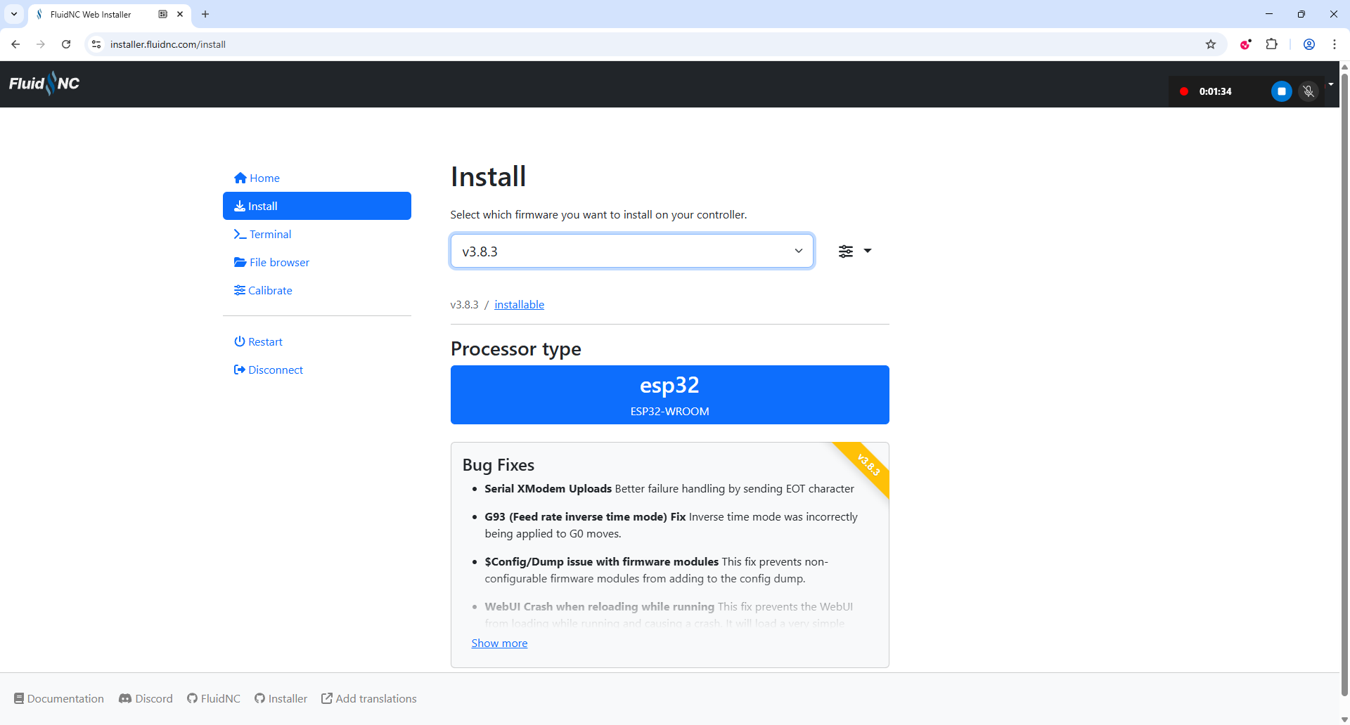
You must then select the preferred version. In my case, I chose version 3.8.3 and clicked on the blue box labeled ESP32 to begin the installation.
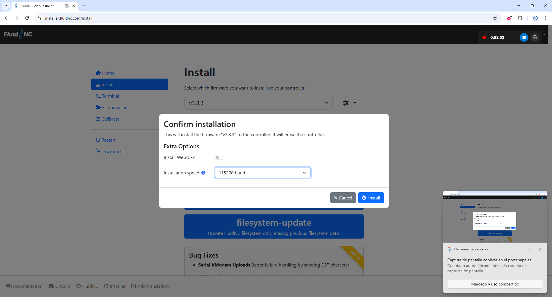
Next, select WiFi and then choose Fresh Install. It is important that after selecting the baud rate and clicking Install, you press the BOOT button on the ESP32 board. This step is essential for the software to be correctly installed onto the microcontroller.
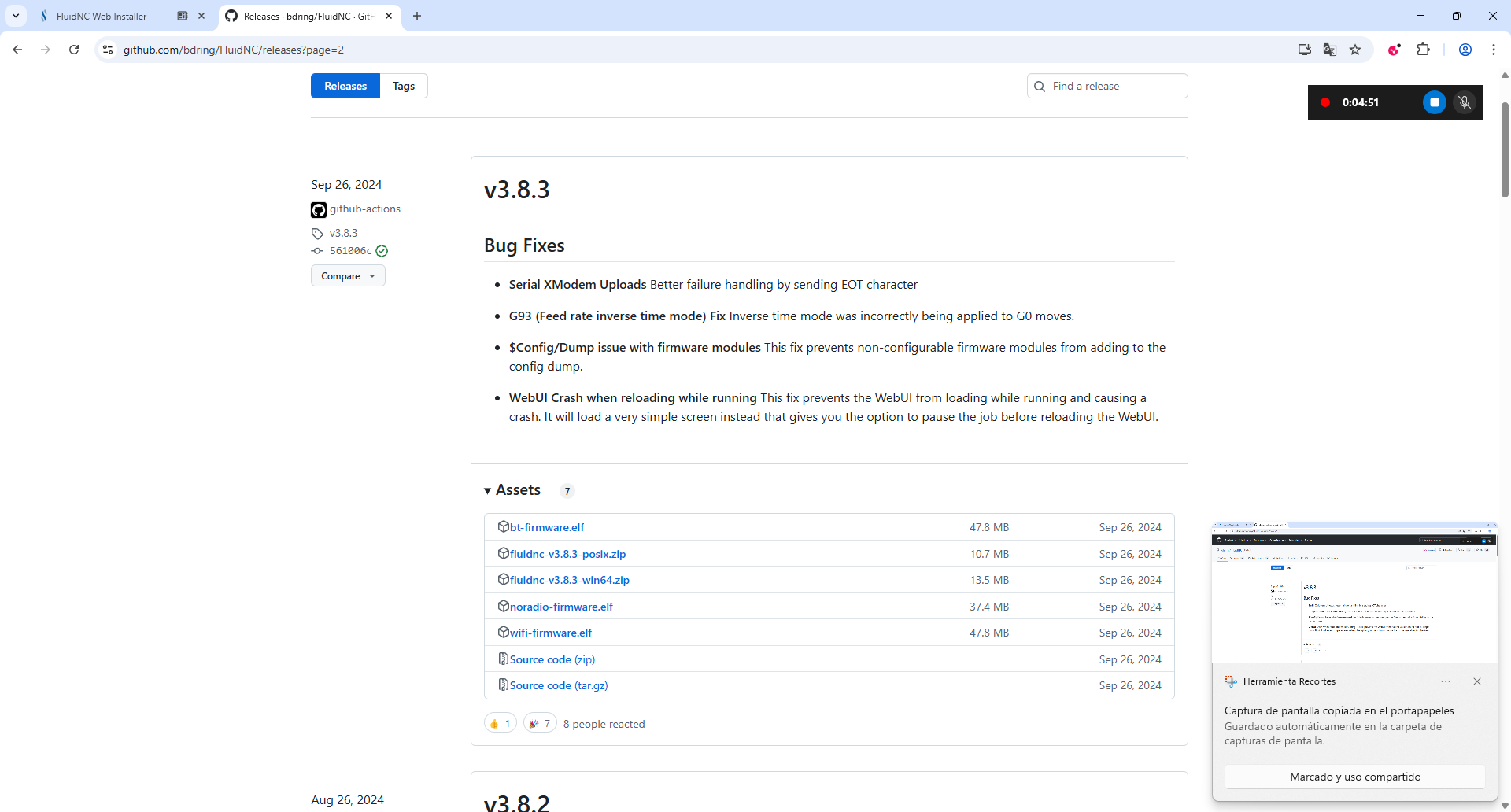
Now, go to the following GitHub link: https://github.com/bdring/FluidNC/releases?page=2 and download the file that ends with win64.zip. This file contains the FluidTerm tool needed to communicate with the ESP32 after installation.
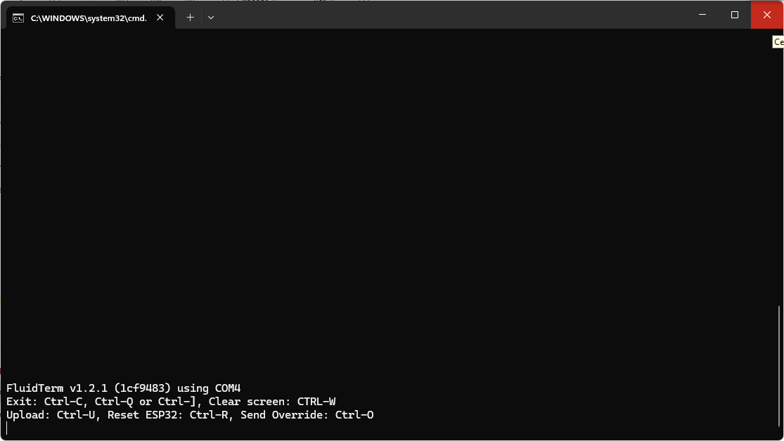
In the unzipped folder, run the "install-wifi" file. This will open a command line console where you must select the port to which your ESP32 is connected.
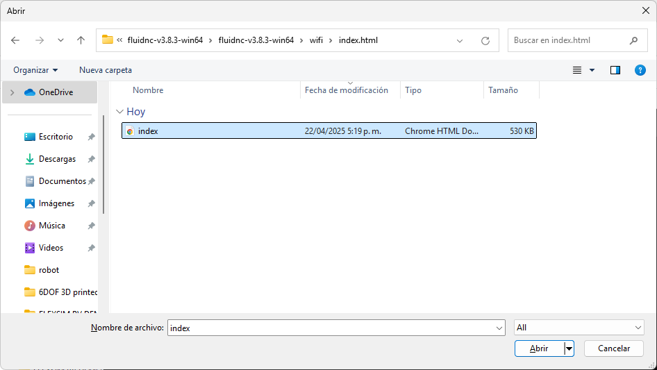
Once inside the console, press Ctrl + U to upload a file directly to the ESP32. Then, navigate to the unzipped folder and select the file named "index".
Press Enter when prompted to enter a name. It's important to note that whenever a file is modified or added via any console to the ESP32, it is recommended to press Ctrl + R to restart the board and ensure the changes are applied correctly.
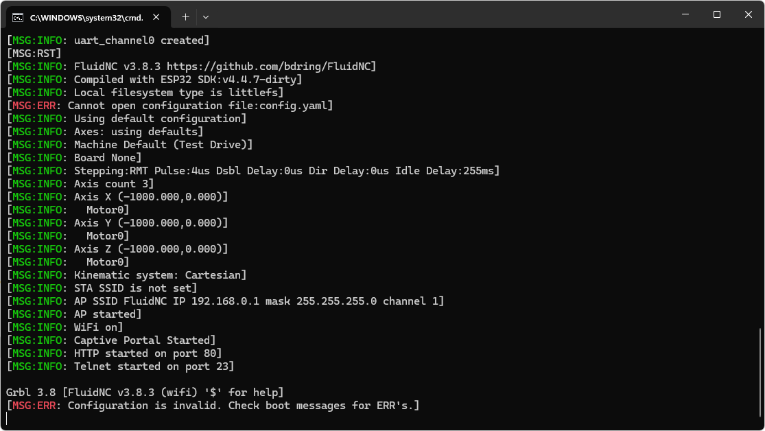
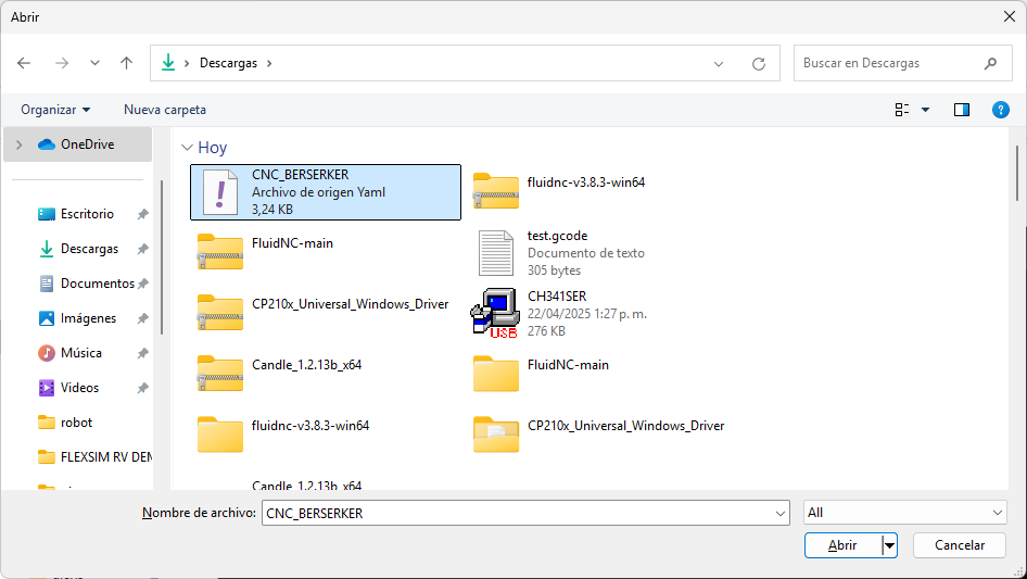
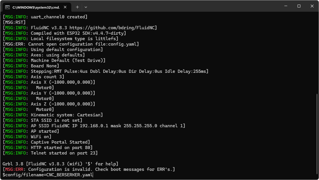
The error that appears is normal and will be resolved once a file with the .yaml extension is introduced and renamed. For this reason, we press Ctrl + U again and upload the file named CNC_BERSERKER. This file contains the machine configuration parameters I mentioned previously. After many trials and adjustments, we finalized a configuration that successfully connects to Candle, the software responsible for sending G-code instructions to the ESP32 to control motor movements.
This configuration was based on the reference found in the following GitHub issue: FluidNC Issue #751, and it was adapted to meet the specific needs of our custom machine. The modifications were focused on optimizing parameters such as motor steps, speeds, and travel limits to ensure precise and reliable operation.
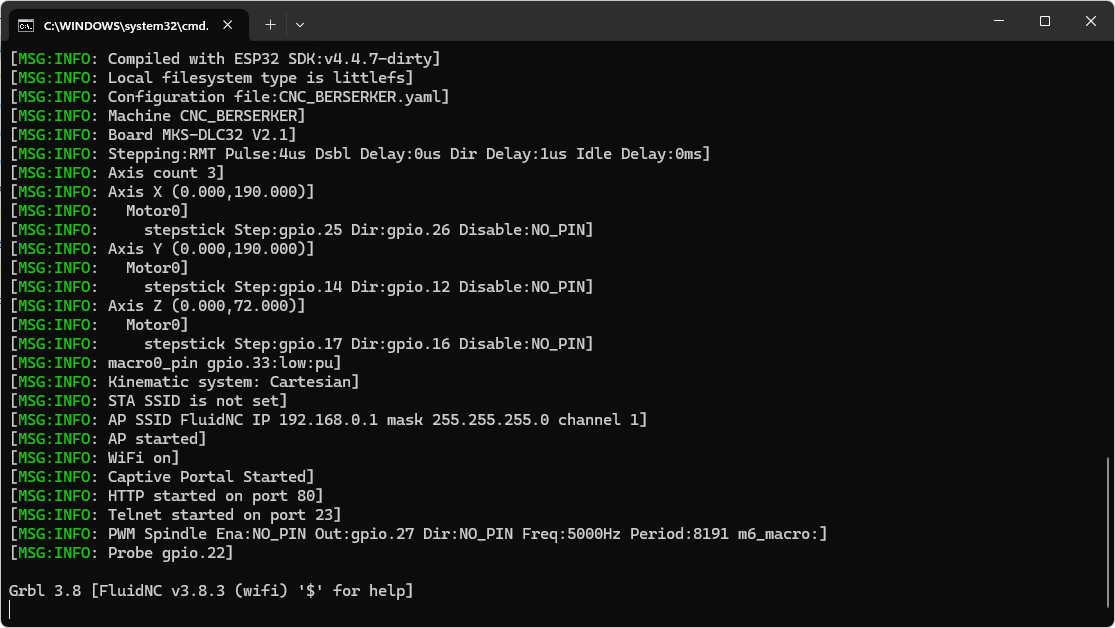
Then, we use the command: $config/filename=CNC_BERSERKER.yaml which resolves the previous error displayed by the ESP32. This command sets the correct configuration file and allows the system to load the machine settings properly for motion control.
Finally, the ESP32 board has been fully configured for the application. It is important to note that the necessary configuration files and supporting documents are available for download at the end of this page.
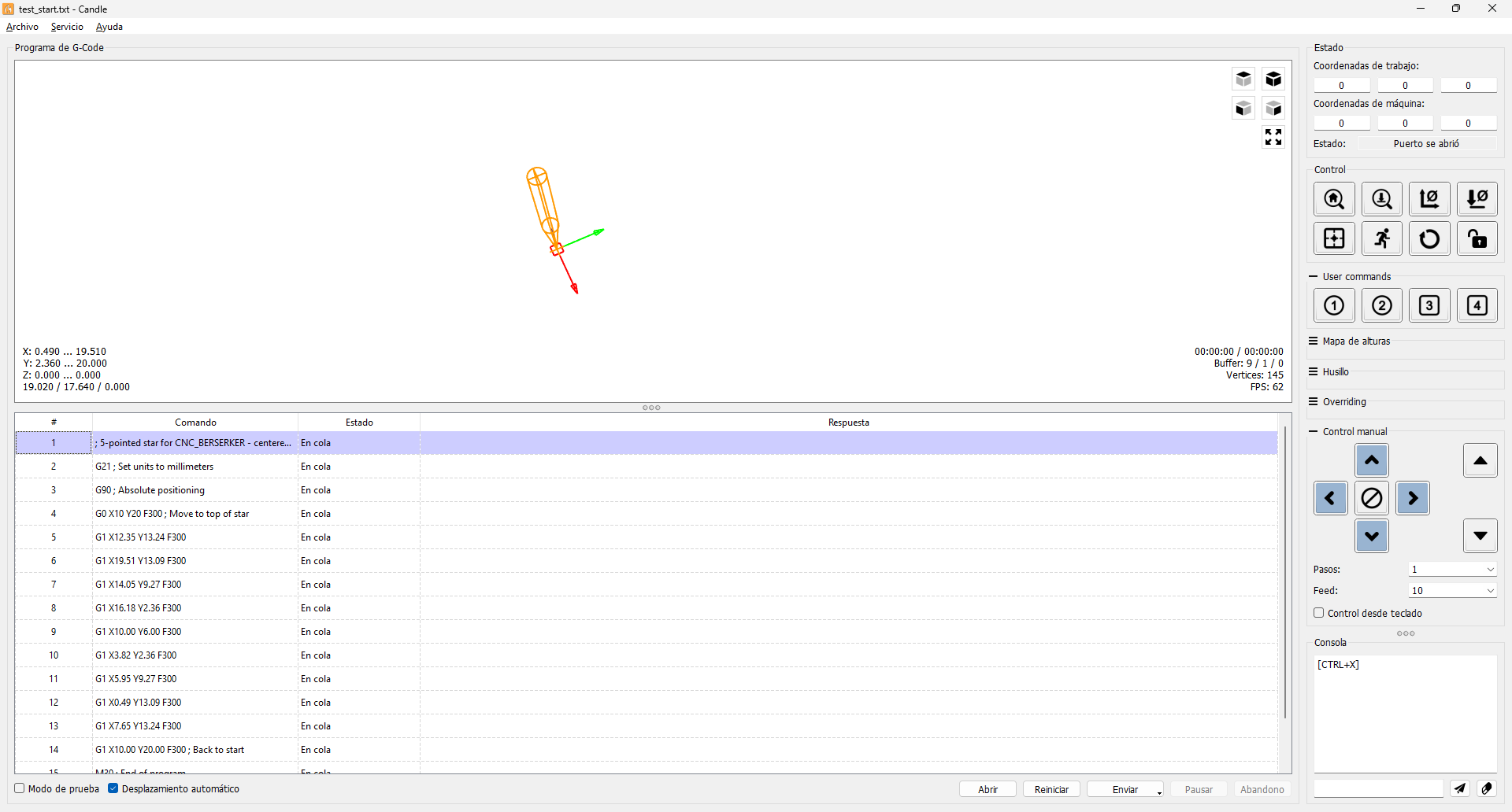
Now, the Candle software must be opened. It can be downloaded from the following link: Candle GitHub Release. Once the program is launched, the interface displays a visualization area for the G-code movements and control panels on the right side that allow manual motor movements.
Execution Test and Results
The following section illustrates the execution phase of our machine. After successfully installing and configuring FluidNC and Candle, the next step was to test the functionality by uploading a G-code file and observing the movement and output produced by the machine.
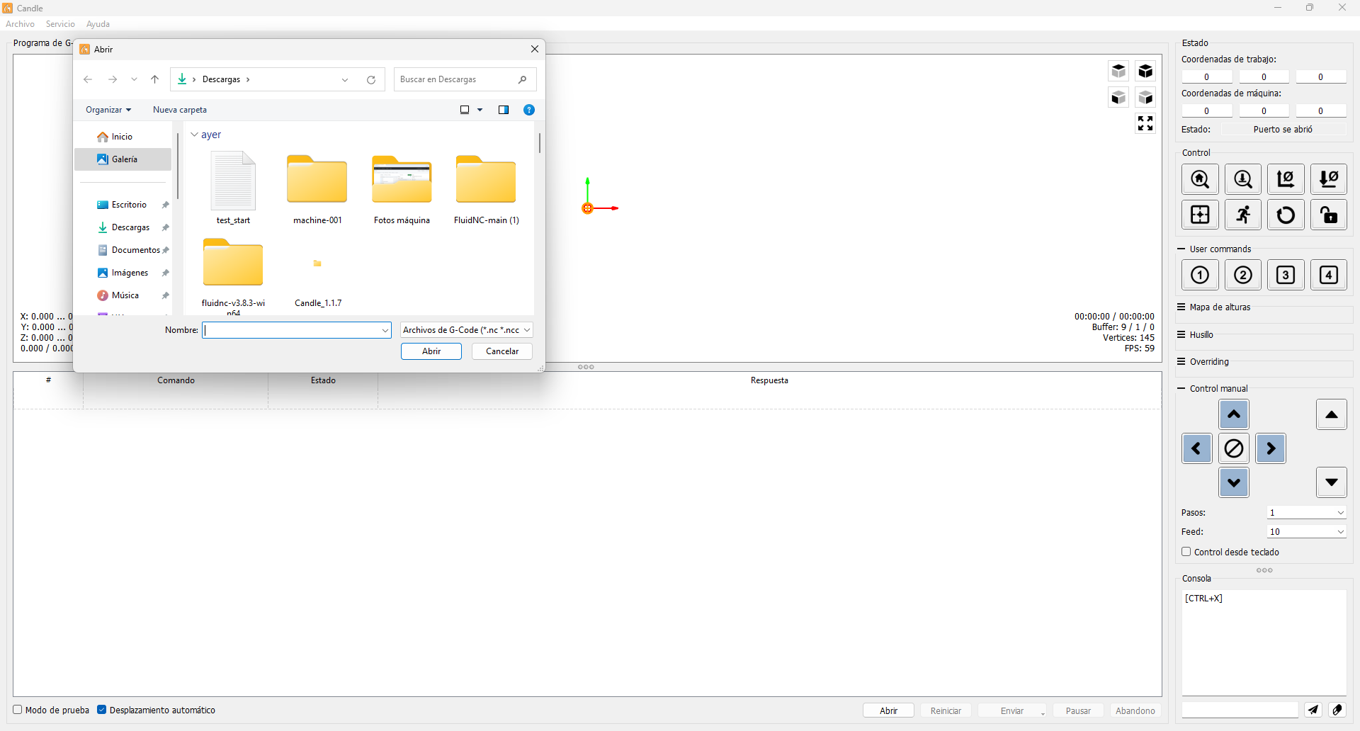
In the Candle software, the option "File > Open" was selected. In the popup window, the .gcode file previously generated by the AI was selected — in this case, a star-shaped design. The file was loaded as plain text, and the toolpath was instantly visualized in the main interface.
As shown in the video, the instructions are ready but pending execution until the "Send" button at the bottom is pressed. It is also possible to observe how the visualization allows us to see the movements that will be performed once the motors are connected.
As a result of the execution, the drawing made by the machine could be observed on the working surface. The pen traced the programmed path accurately, validating both the hardware setup and the uploaded G-code.
Conclusions and Reflections
During the development of the electronic control for our machine, I faced several challenges that significantly enriched my understanding of embedded systems and collaborative design. One major difficulty was the adjustment of the reference voltage on the motor drivers. In the process, I mistakenly connected the reference voltage and ground lines, which led to the failure of three drivers.
This experience taught me the importance of carefully managing power when integrating a high-amperage power supply into a low-voltage control circuit. I also learned how to implement and interface electronic components such as the ESP32, stepper motors, drivers, and the modular 12V 30A power supply to ensure proper communication and functionality.
My main contributions focused on the electronics and firmware: setting up the interface between the microcontroller and the drivers, handling the programming and serial communication between the ESP32 and the computer, and obtaining repurposed electronic components from a disused 3D printer. Another crucial task was identifying and executing the full firmware replacement process, as well as configuring the required files—especially the one that defines workspace limits, speeds, and mechanical characteristics compatible with Candle.
Lastly, I realized how vital it is to maintain open and constant communication when working on a collaborative mechanical design. Feedback and input from different teams influence not only how the system is implemented, but also the feasibility and performance of the overall solution.
Downloads and Project Files
The following files contain the firmware configuration, motion control definitions, and G-code used for testing the machine. These resources are essential to replicate the setup, explore the electronic control, or adapt it for future projects.