Week 13
Molding and Casting
Week Overview
During this week, I explored two different approaches to mold making for custom candles. First, I designed geometric models in Fusion 360 and produced positive molds using both 3D printing and CNC machining in wood. I then poured silicone over each positive to create flexible negative molds. Finally, I used both silicone molds to cast paraffin wax candles in various shapes, comparing the results and process for each fabrication method.

The final result: three custom candles, ideal for meditation or reflection.
Group Assignment
As part of the group assignment, we documented:
- Review the safety data sheets for each of your molding and casting materials
- Make and compare test casts with each of them
- Compare printing vs milling molds
Individual Assignment: Molding and Casting
1. Importing the Reference Mesh into Fusion 360
The first step in my process was to import a reference mesh file into Fusion 360. This mesh served as the basis for designing the positive models that would later be used to create the mold. Importing the mesh allowed me to accurately align and scale the geometric shapes according to my project requirements.
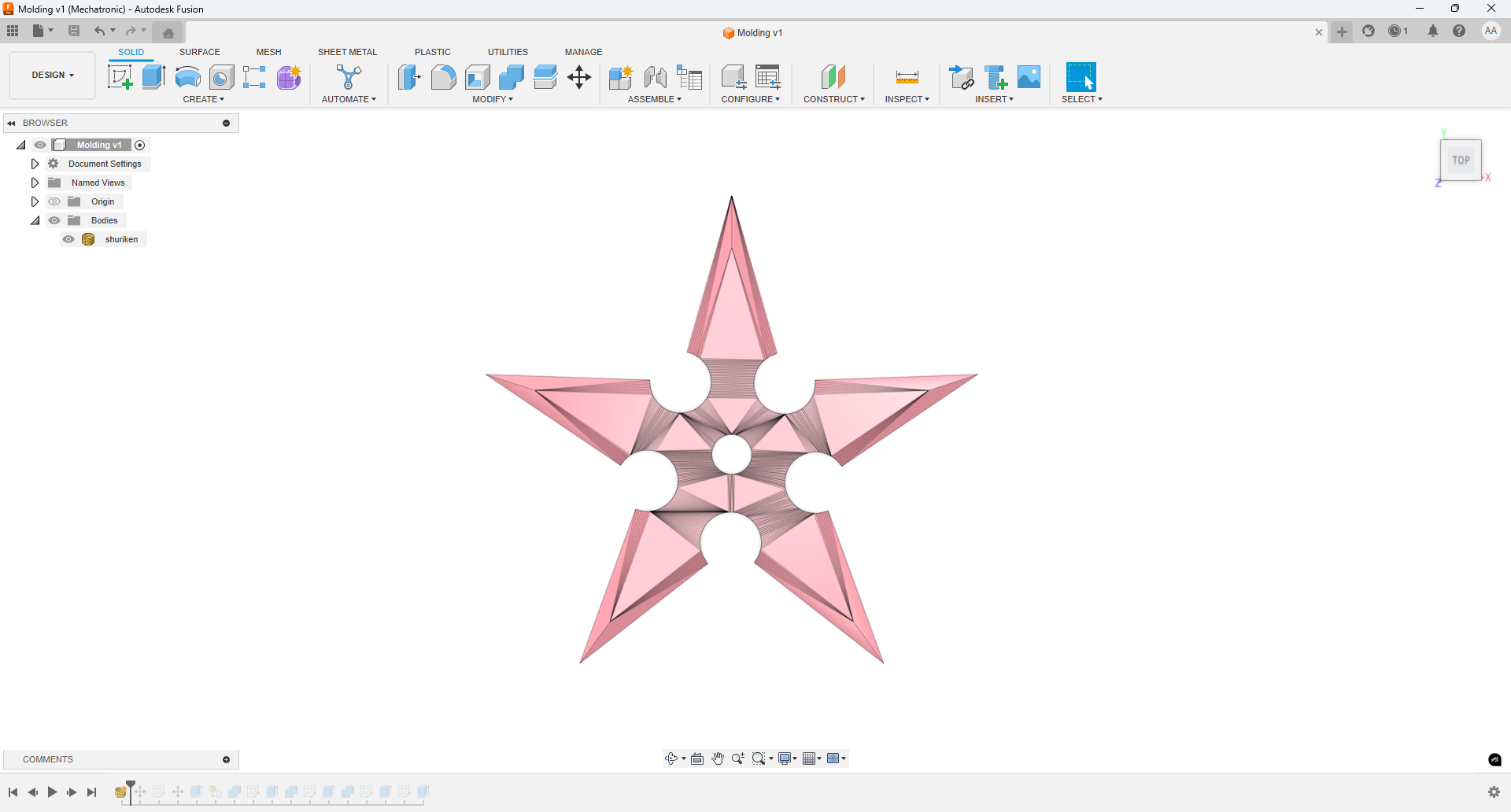
Reference mesh imported into Fusion 360.
Creating the Base for the Mold
Next, I created a base in Fusion 360, making sure it covered up to half of the generated design.
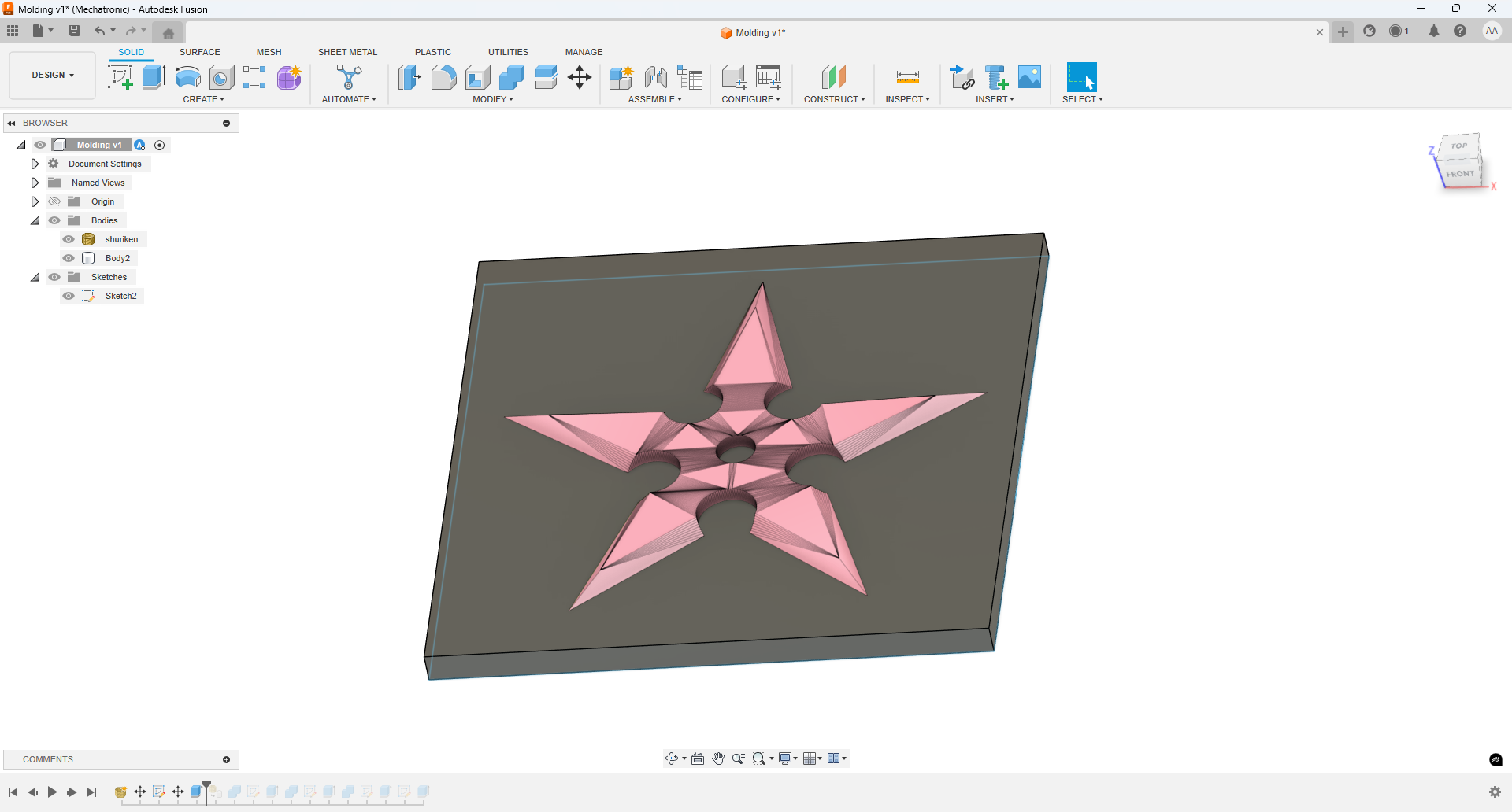
Base created in Fusion 360 to cover half of the design.
Generating the Mold Cavity with Combine > Cut
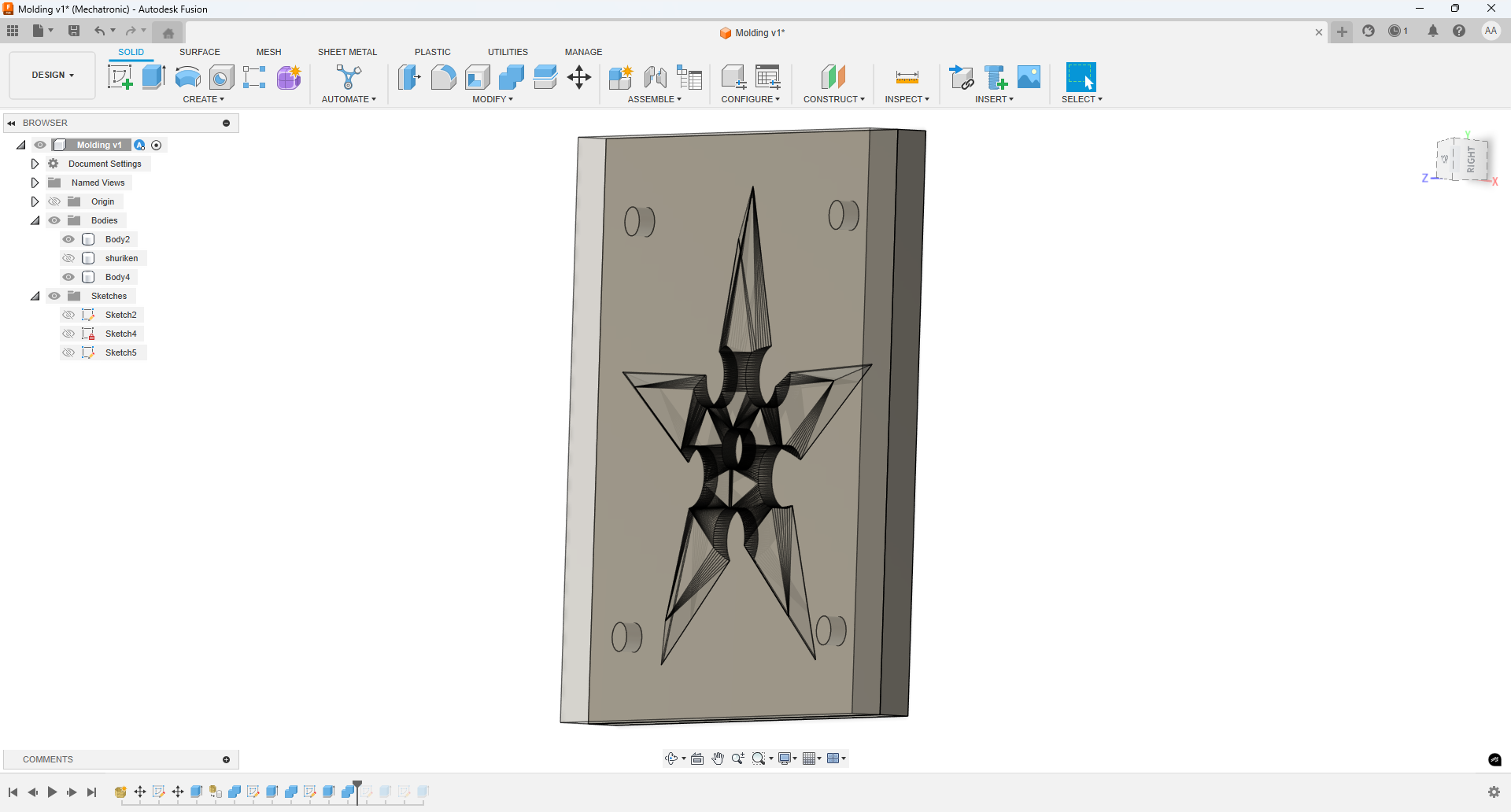
Using the Combine feature in Fusion 360, and specifically the Cut operation, I was able to subtract the positive model from the base. This process created a cavity in the base, accurately representing half of the desired shape. The result is the negative space that will be used for the molding process.
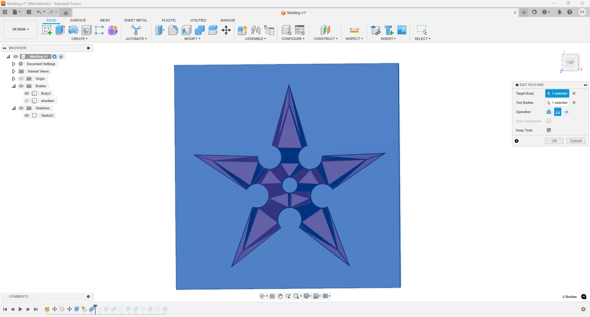
The mold cavity generated using the Combine > Cut operation in Fusion 360.
Creating the Second Half of the Mold
Next, I created the other half of the mold by designing a second base in Fusion 360. I then positioned this base above the positive model and used the same intersection technique to generate the cavity. This ensured that both halves of the mold would fit together perfectly around the shape, allowing for accurate casting.
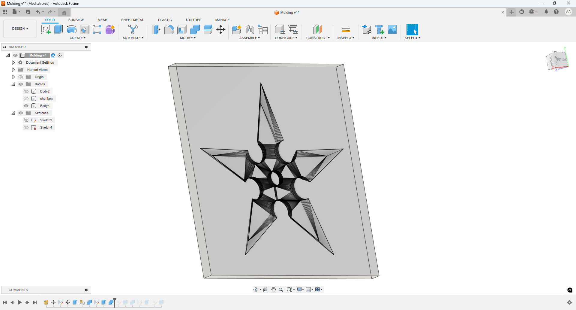
Second mold half created and intersected with the positive model in Fusion 360.
Adding Alignment Pins
To ensure that both halves of the mold fit together accurately during the casting process, I added alignment pins. This feature helps to avoid any displacement or misalignment when assembling the mold.
Alignment pins designed in Fusion 360 to guarantee a perfect fit between mold halves.
Adding a Pouring Hole
As the final step in the mold design, I added a pouring hole on one side of the mold. This hole allows for the easy introduction of melted paraffin into the mold cavity during the candle-making process. Its size and location were chosen to ensure smooth filling and to minimize air bubbles inside the finished candle.
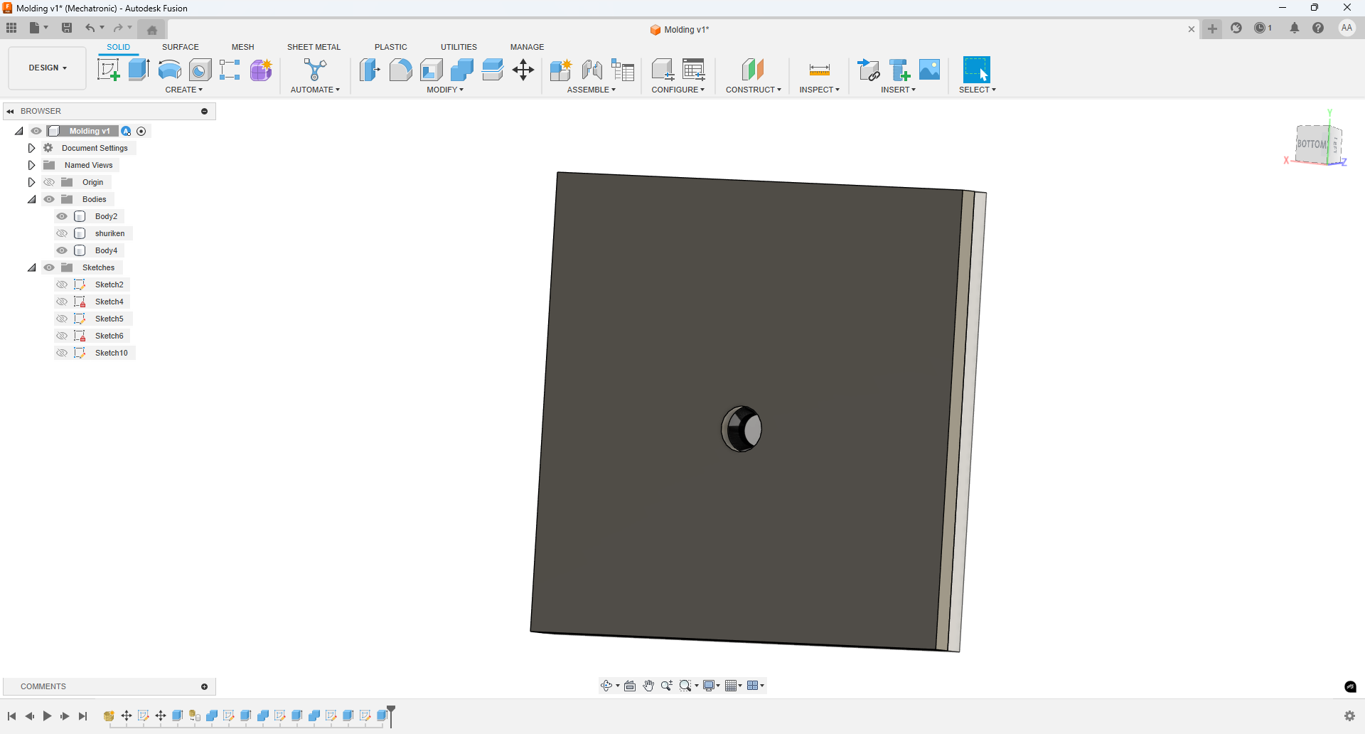
Pouring hole designed to introduce paraffin into the mold cavity.
Exporting the STL and Setting Up the Print in OrcaSlicer
After exporting the model from Fusion 360 in STL format, I used OrcaSlicer to configure the 3D printing parameters.
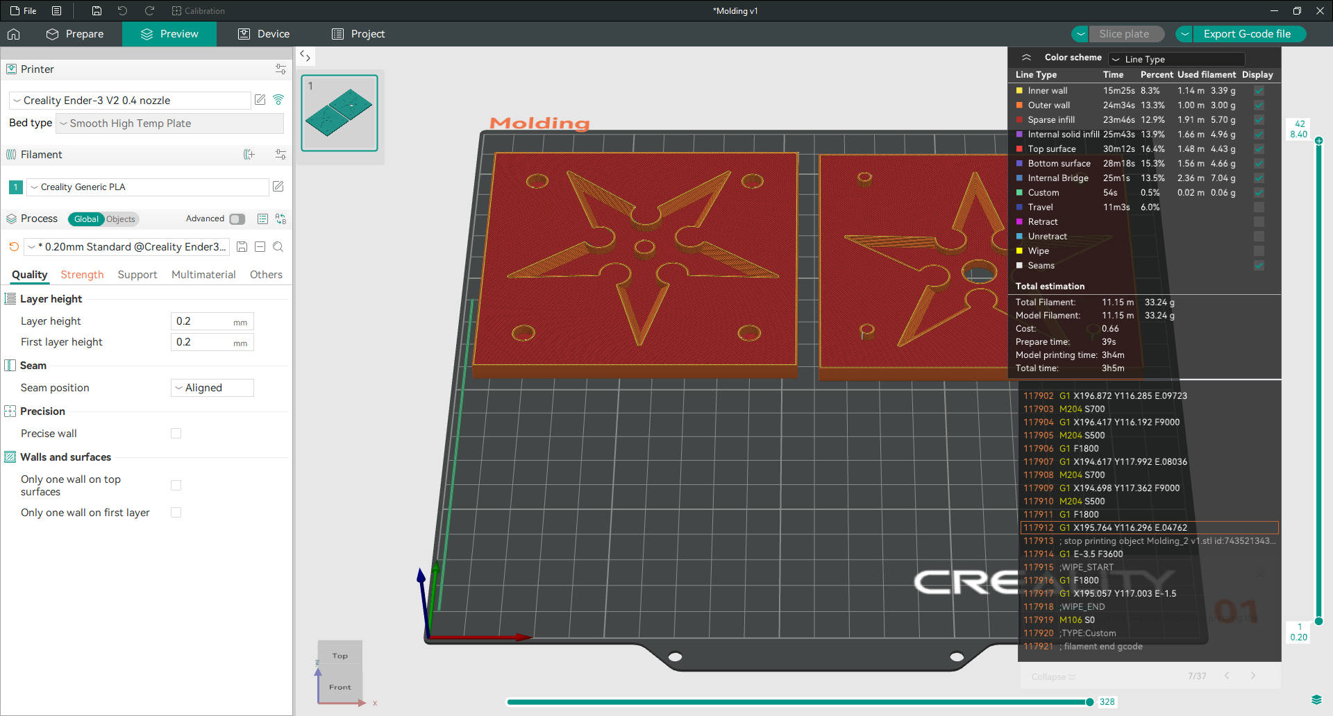
3D printing parameters set in OrcaSlicer for the mold.
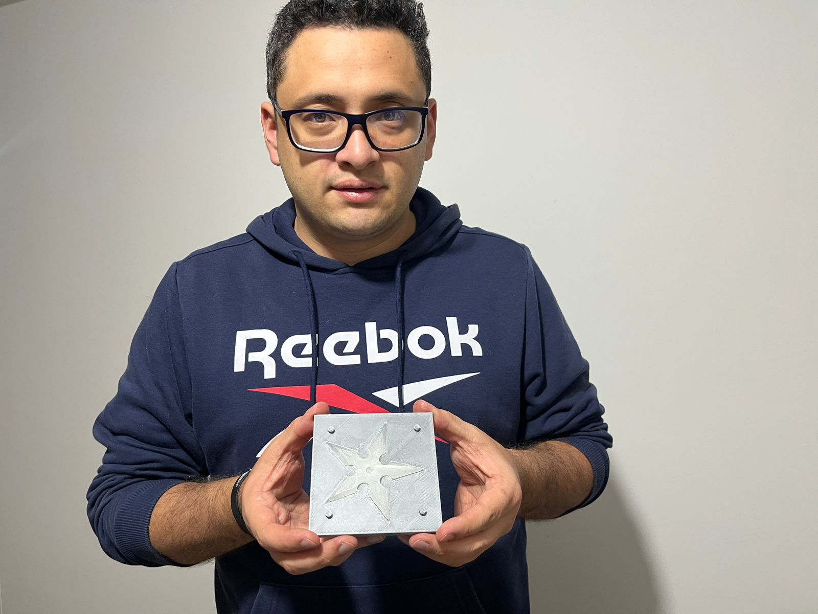
3D Printing the Mold
To better illustrate the fabrication process, here is a short video showing the mold being printed on the 3D printer. This step was crucial to achieve accurate shapes and a good surface finish for the subsequent silicone casting.
Short clip of the mold being 3D printed.
Melting the Paraffin Wax
Before pouring the candles, I melted paraffin wax using a heat-resistant container. Once the wax was fully melted, it was ready to be poured into the prepared silicone mold.
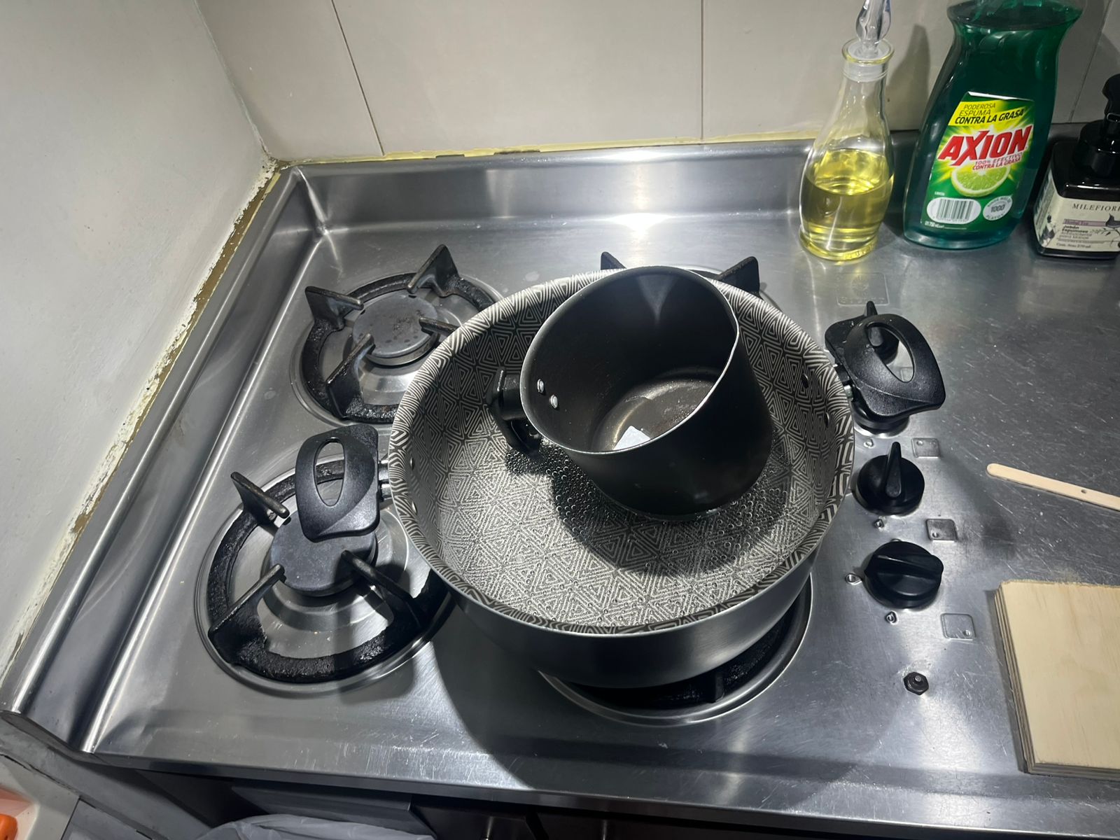
Melting paraffin wax in preparation for pouring into the mold.
Pouring the Paraffin into the Mold
In this video, you can see how I pour the melted paraffin wax into the silicone mold. Before pouring, I sealed the edges of the mold with tape to prevent any leakage of wax through undesired gaps. This step ensured a clean casting process and well-defined candle shapes.
Video showing the process of pouring paraffin wax into the sealed mold.
Demolding and Final Result
In the image below, the left side shows the candle immediately after removing one half of the mold. The right side displays the final result after fully extracting the candle from the silicone mold.
Left: Candle after removing one half of the mold. Right: Final candle completely demolded.
Milling Molds: Setting Material Dimensions
For the milling mold process, the first step was to input the exact dimensions of the available material into the CAM software. This ensured that the design would fit properly within the wooden stock prepared for machining, and minimized the risk of running out of space during the milling operation. The following image shows the dimensions set in the software interface.
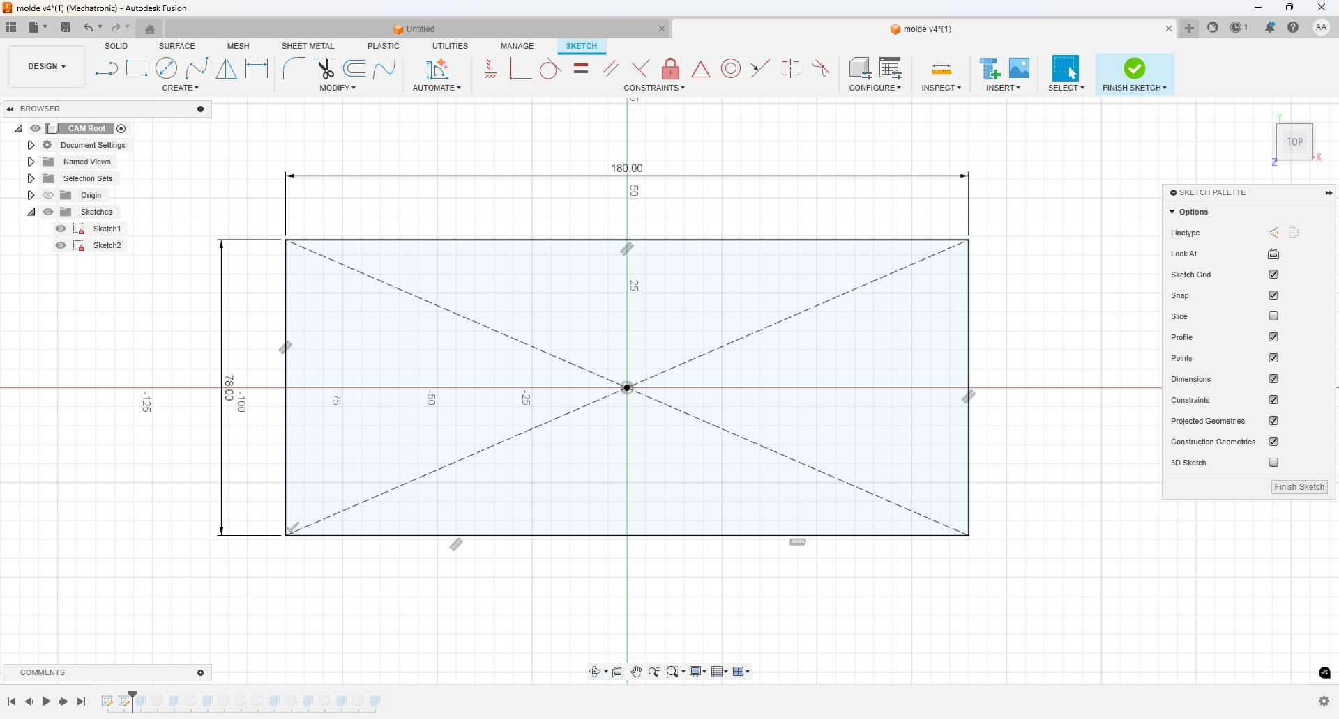
Setting the dimensions of the wooden stock in the CAM software before milling.
Adding Margins and Extruding the Cavity
Next, I added a margin between the designs and the edges of the material to ensure structural integrity during milling. After setting the margins, I extruded the main cavity into the wooden block. This cavity was created deep enough to fit the positive models I previously designed, providing enough space for pouring the silicone later.
Extruding the main cavity with margin from the edge of the wooden stock.
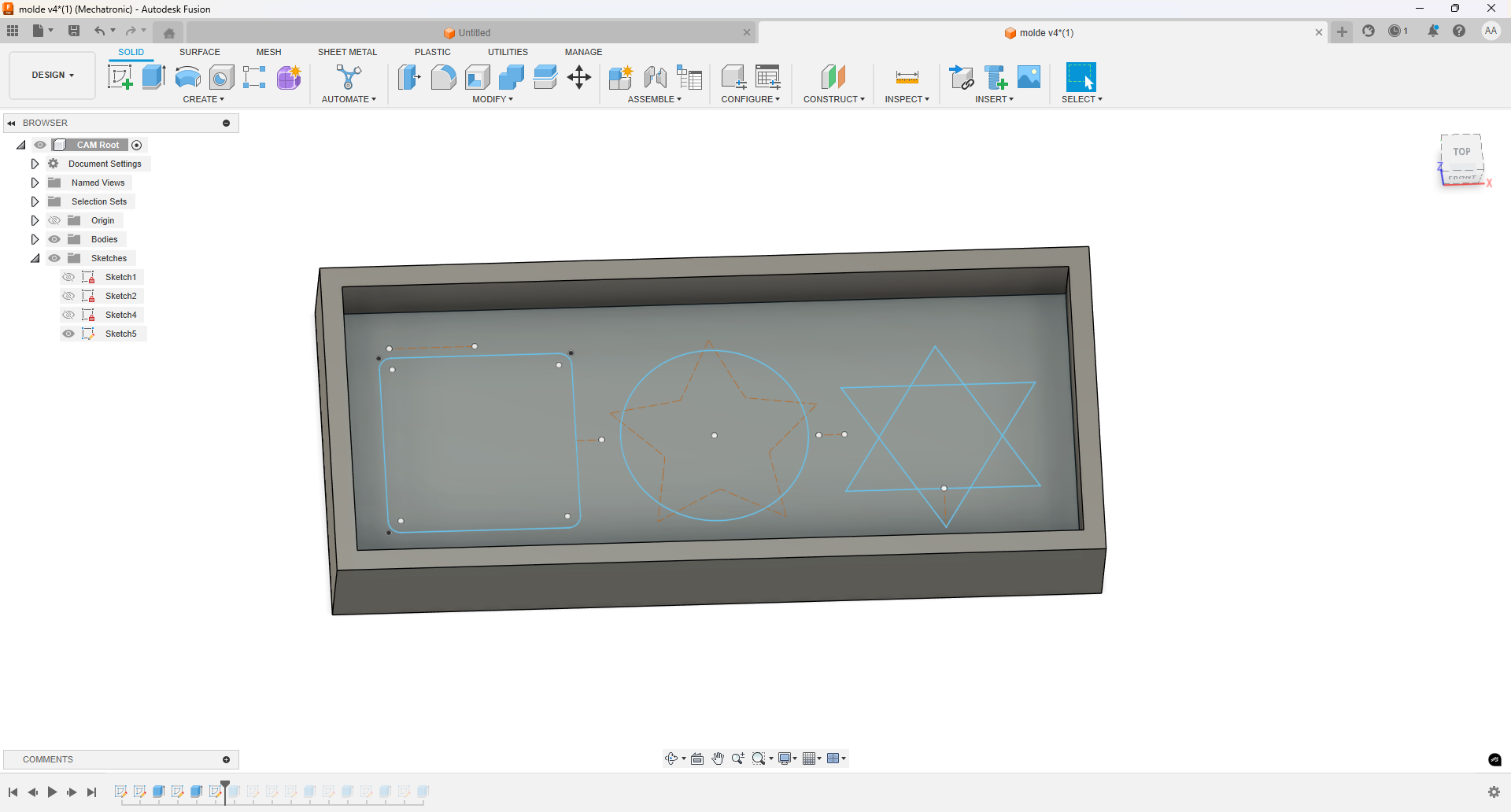
Adding More Complex Features to the Design
After creating the basic shapes, I built additional figures on top of the existing ones to add more complexity to the design. This step allowed me to experiment with multi-level features and a more intricate geometry for the final mold. The following image shows the completed design, ready for the milling process.
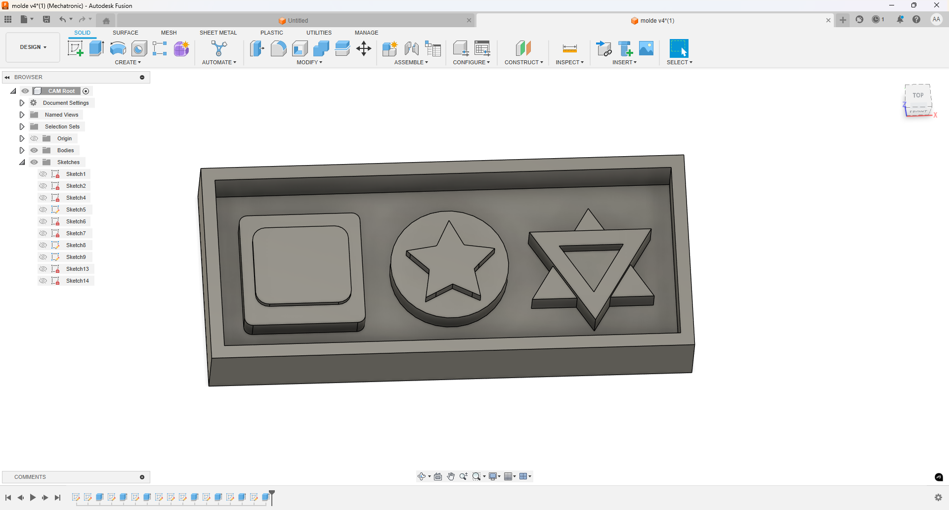
Final design with added complexity, ready for milling.
Selecting the Recommended Tool
In the manufacturing section of the CAM software, I selected the cutting tool recommended by the Fab Lab staff for this type of material and design. Choosing the right tool is essential to achieve a good surface finish and to avoid damaging the wooden block or the machine. The image below shows the selected tool configuration in the software.
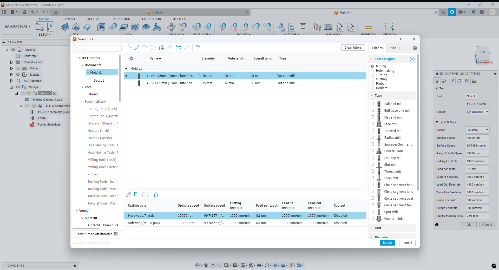
Selecting the recommended cutting tool in the CAM software.
Adjusting Tool Speeds
After selecting the appropriate cutting tool, I adjusted the spindle speed and feed rates in the CAM software. These parameters were fine-tuned based on the material properties and tool specifications to ensure efficient machining and a high-quality surface finish. Proper speed settings also help to prolong the life of the tool and prevent burning or tearing the wood.
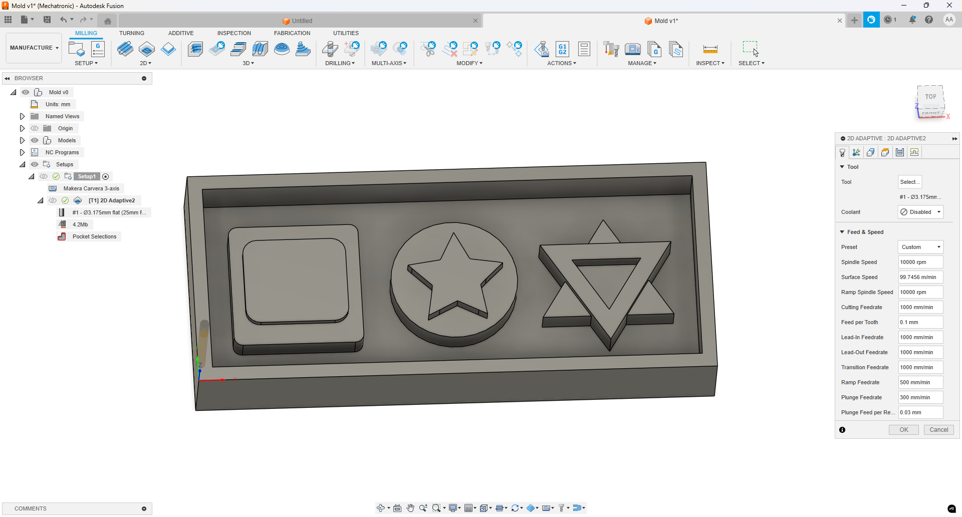
Tool speed and feed rate settings configured in the CAM software.
Selecting Pocket Operations for the Geometry
In the geometry section of the CAM software, I used the pocket operation to select all the surfaces that needed to be machined. This approach allowed the tool to efficiently remove material from specific areas, creating the desired cavities and features in the wooden block. Careful selection ensured accurate machining and preserved the details of the design.
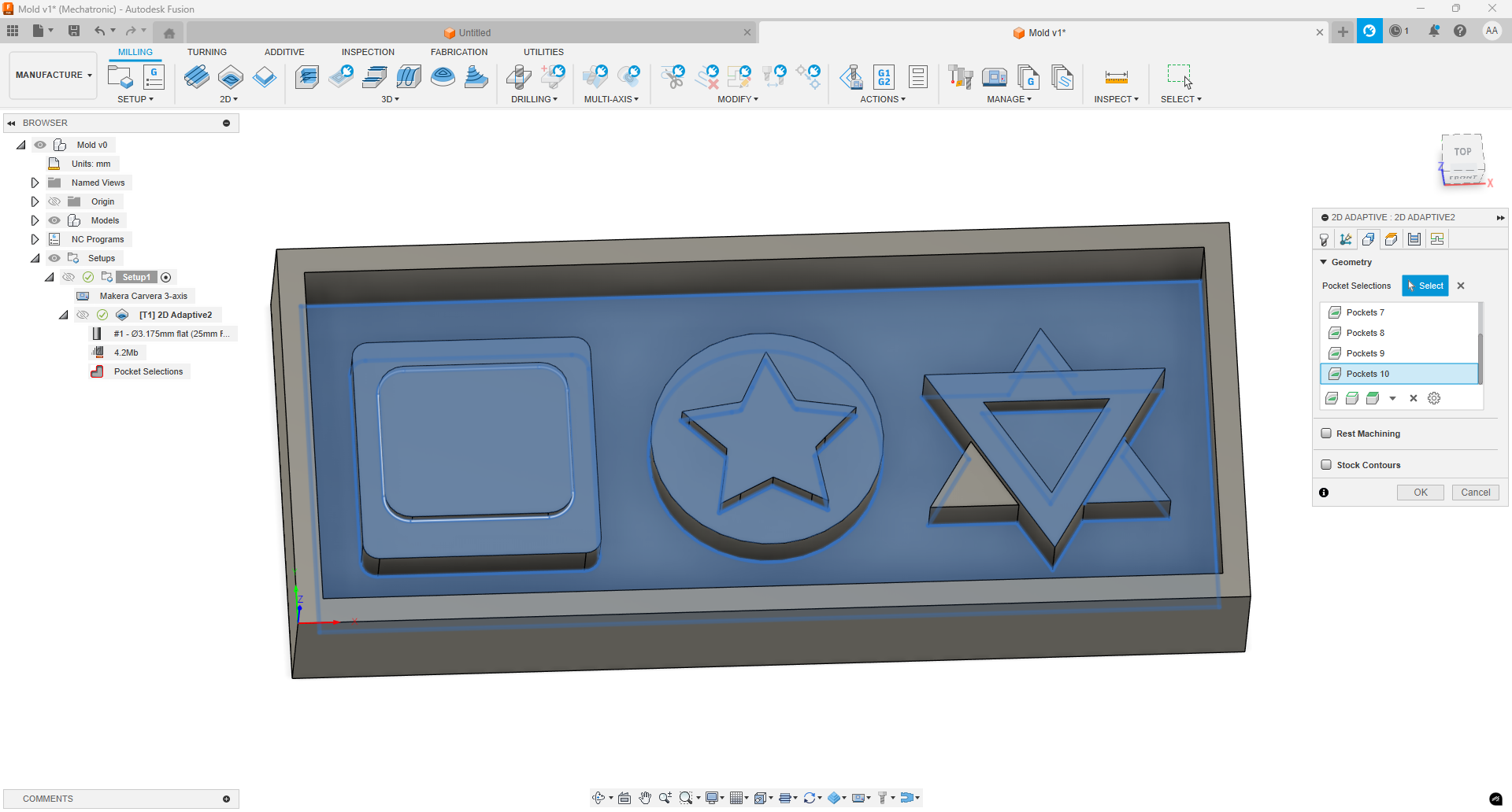
Pocket operations selected for the desired surfaces in the geometry section.
Configuring Helix Ramp and Safety Parameters
In the linking section of the CAM software, I set the ramp entry to a helix pattern. This approach provides a gradual entry for the cutting tool, reducing stress and minimizing the risk of tool breakage. Additionally, I configured safety parameters such as clearance and retraction heights to protect both the tool and the workpiece during non-cutting movements.
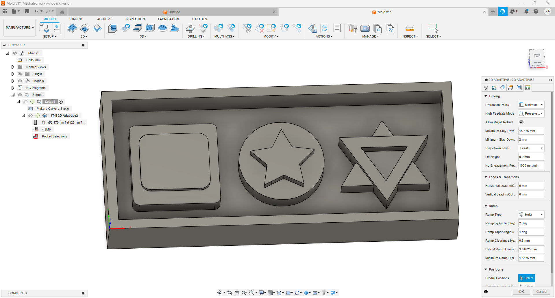
Helix ramp entry and safety settings configured in the linking section.
Simulating the CNC Milling Process
The following video shows the simulation of the CNC milling process as configured in the CAM software. This simulation allowed me to verify the tool paths, entry strategies, and safety parameters before running the job on the actual machine, helping to prevent potential errors or collisions.
Video simulation of the configured CNC milling process.
CNC Milling Process: During and After
The following images show the process while the CNC machine was operating, and the result after the milling job was completed.
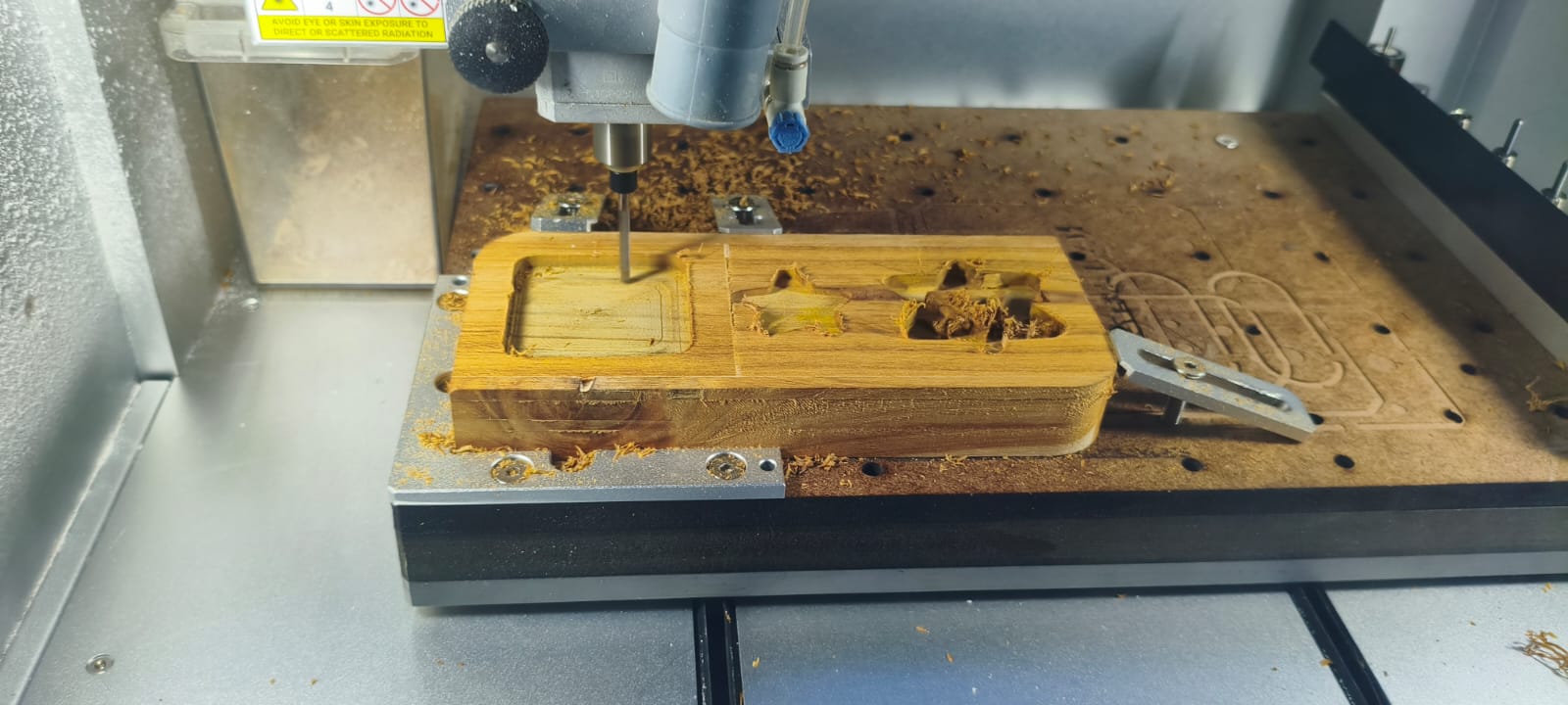
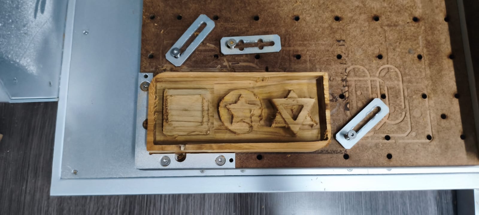
Top: The CNC machine in operation. Bottom: The final result after completing the milling process.
CNC Operation Videos
The following videos show different moments of the CNC milling operation. The first video captures the beginning of the process, while the second video shows the final passes and the completed work.
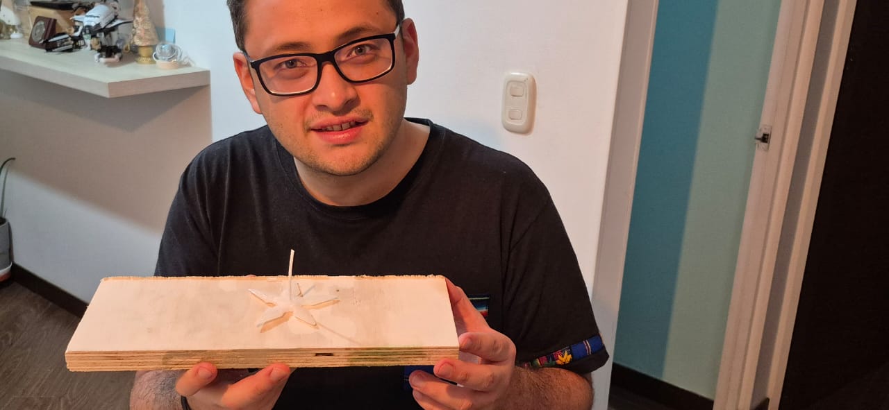
Finished Wooden Mold and Varnishing
Here you can see the completed wooden mold after the milling process. I applied a coat of varnish to the surface to seal the wood and prevent the silicone from leaking through the pores or picking up surface imperfections. This finishing step is essential for achieving a smooth, defect-free silicone mold in the next stage.
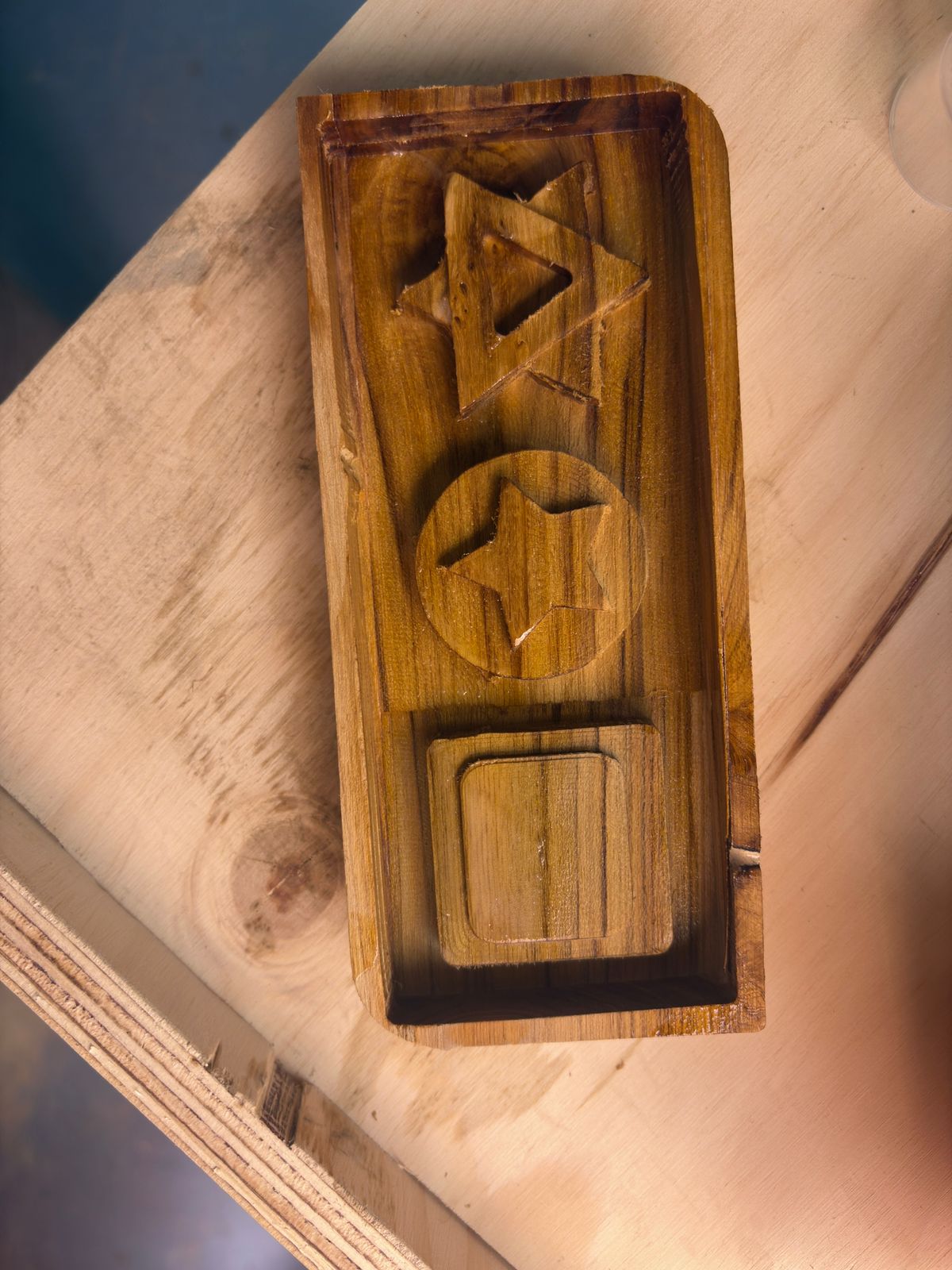
The finished wooden mold with a protective layer of varnish.
Mixing the Silicone Rubber
I prepared the silicone by mixing equal parts of component A and component B from the Super Elastic Platinum Silicone Rubber (BBDINO brand). I carefully measured both components to ensure an accurate 1:1 ratio, and the total weight of the final mixture was 177 grams. Thorough mixing is essential to achieve optimal curing and elastic properties.
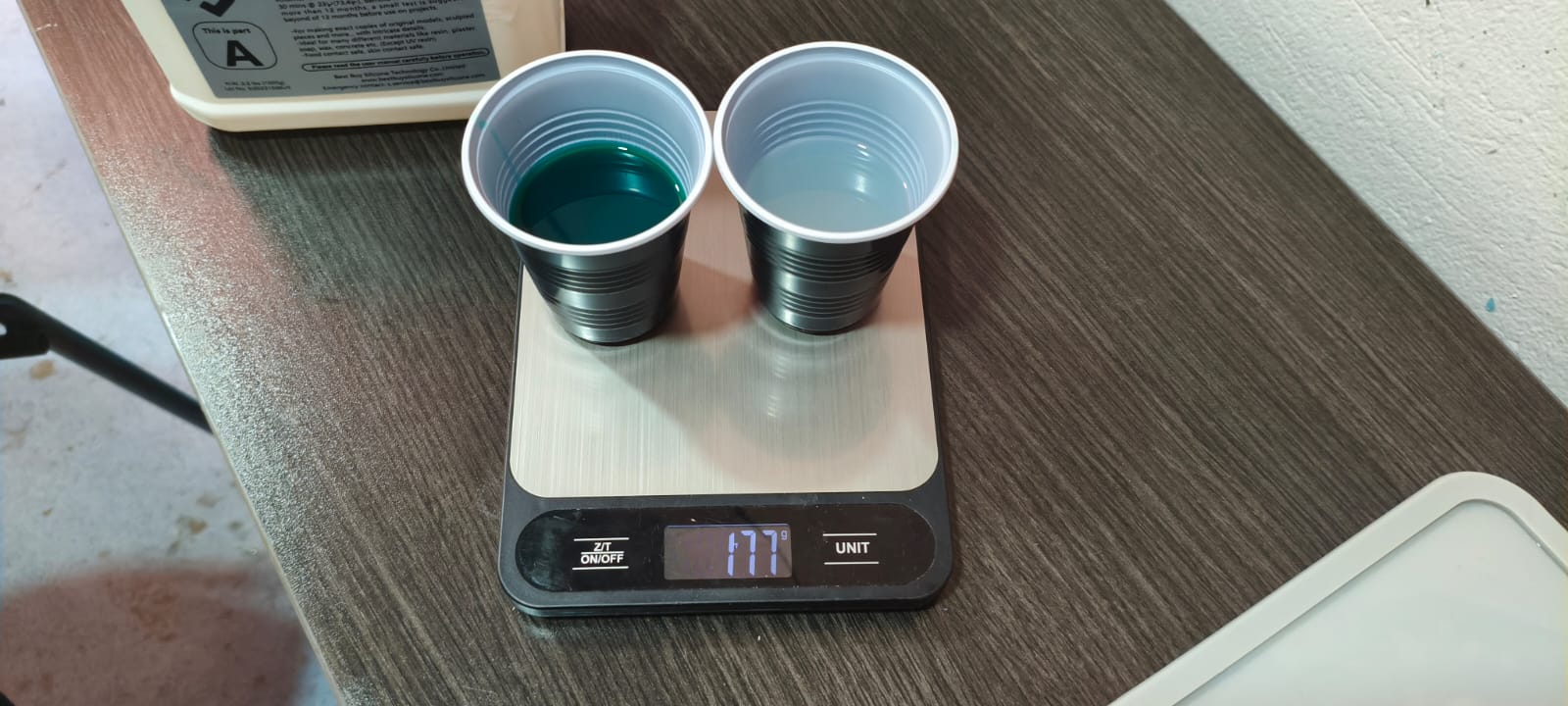
Mixing equal parts of Super Elastic Platinum Silicone Rubber (BBDINO), for a total of 177 g.
Pouring the Silicone into the Mold
In the following video, I pour the thoroughly mixed silicone rubber into the prepared wooden mold. I made sure to fill the entire cavity evenly to avoid air pockets and to capture all the details of the design.
Pouring the silicone mixture into the varnished wooden mold.
Mold Filled and Ready for Curing
In the image below, the wooden mold is completely filled with the silicone mixture and ready to be left to cure for 24 hours. Ensuring the mold is fully filled helps prevent air bubbles and ensures an accurate reproduction of the original design.
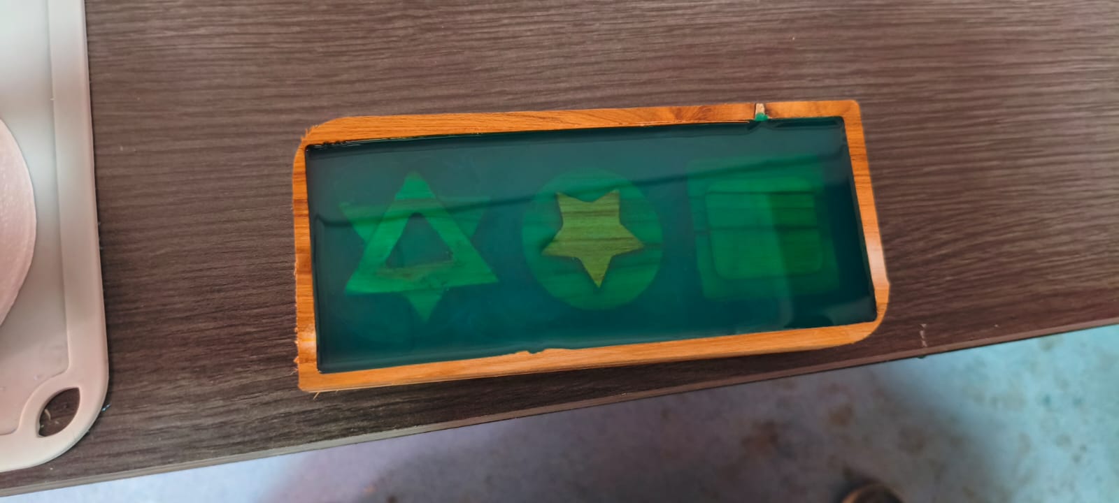
Mold filled with silicone mixture, ready to cure for 24 hours.
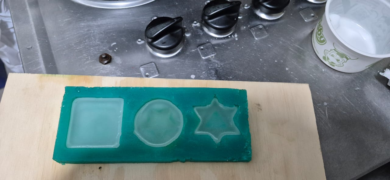
Final Result After Curing
After letting the silicone cure for 24 hours, the results can be seen in the following images. The silicone mold was successfully removed from the wooden form, showing a flexible and detailed negative ready for casting.
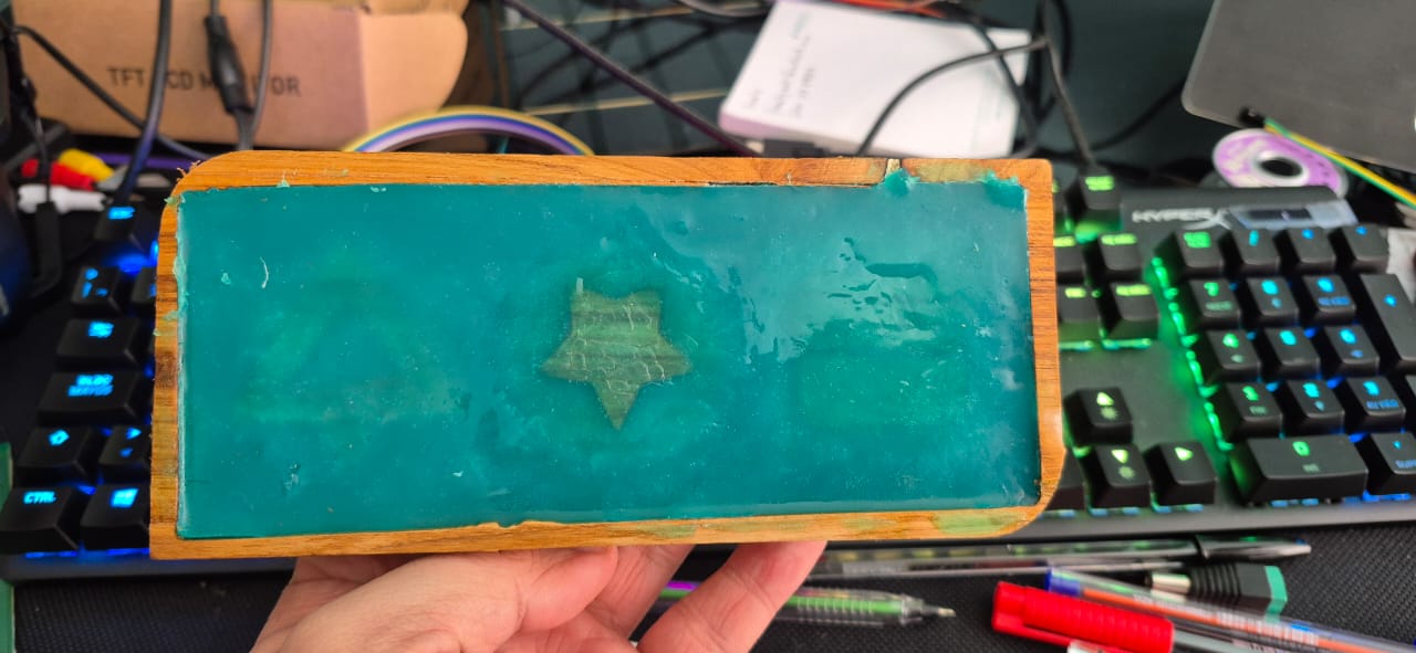
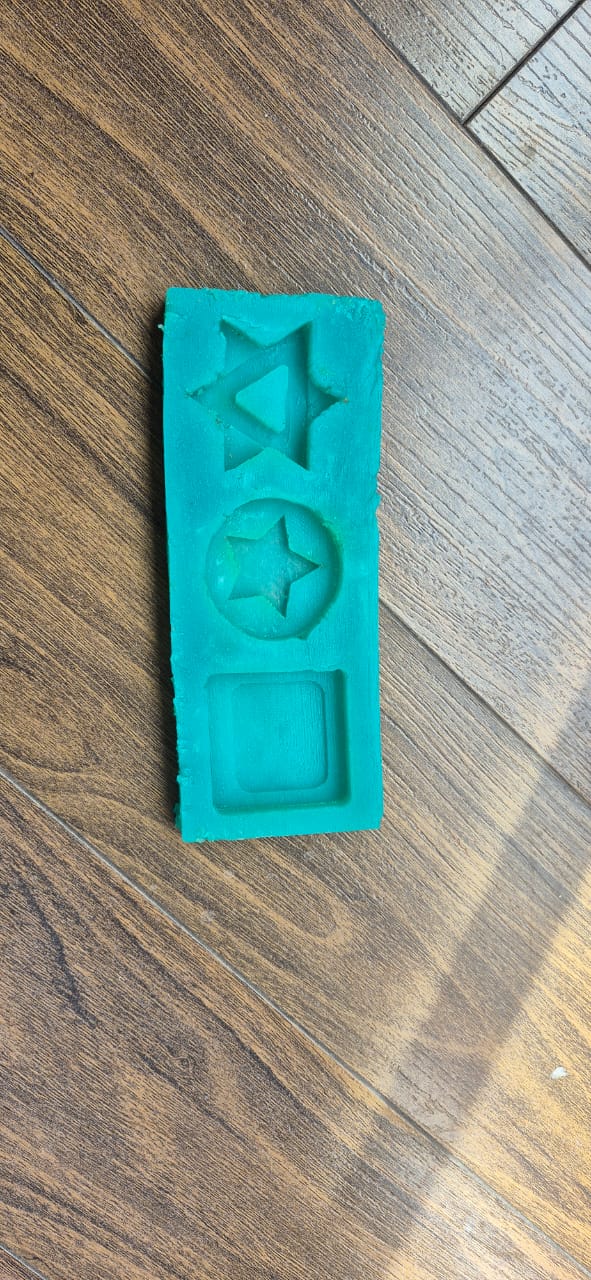
Top: The silicone mold after 24 hours of curing. Bottom: The mold completely removed from the wooden form.
Casting Candles with Paraffin Wax
I also used paraffin wax to make candles by pouring the melted wax into the finished silicone mold. The flexibility of the silicone ensured easy demolding and a clean surface finish for the candles. The following image shows the process of pouring paraffin into the mold.
Pouring paraffin wax into the silicone mold to make custom candles.
Final Result: Three Handmade Candles
After a lot of effort, the final result was three beautiful candles, perfect for meditation or short periods of reflection. Each candle preserved the geometric shapes designed at the start of the project, demonstrating the effectiveness of the molding and casting process.
The final result: three custom candles, ideal for meditation or reflection.
Reflections and Learnings
This week was a valuable opportunity to explore and compare different techniques for mold making and casting. I learned the importance of precision in digital design, whether for 3D printing or CNC milling, as even small errors can affect the quality of the final product. Working with both manufacturing methods provided insight into their unique advantages and limitations: 3D printing is flexible and accessible for rapid prototyping, while CNC machining allows for robust molds with high dimensional accuracy.
The casting process taught me to pay attention to surface finish, material compatibility, and proper sealing of the molds. I also gained practical experience with silicone preparation and paraffin casting, as well as troubleshooting issues like leakage and air bubbles.
Overall, this assignment reinforced the value of hands-on experimentation, iterative problem-solving, and careful planning in digital fabrication. I am now more confident in my ability to create custom molds for a variety of applications, and I see new creative possibilities for future projects.
Downloads
Below are the files associated with this week’s assignments. These downloads include the design files, toolpaths, and reference documents used throughout the molding and casting process.