Final Project
Motorized Hidden Pop Up Shelf
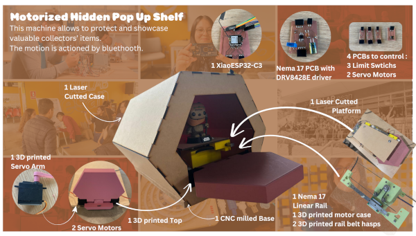
Motorized Hidden Pop Up Shelf

I donwloaded the files to printed them, and to have an idea about dimensions. Because I need to test the diferent funko models, not every model present same characteristics. So I can decide if I could used packed or unpacked funkos. I have some problems when printing. i think that it was because my filament was expose to much time to humity.
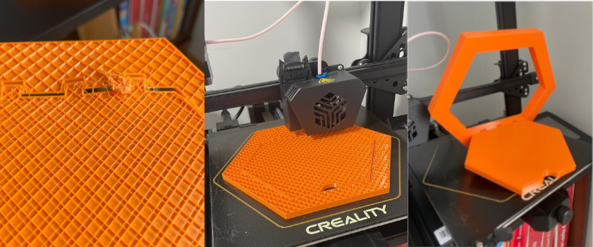
I test product dimensions using different kind of funkos, because some special design are wider or taller. So I can decide for which kind of funkos I will develop my final design. I also notice that build something for the unpacked funkos will need something bigger

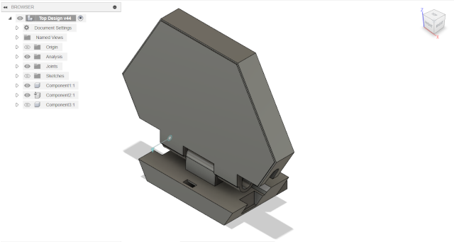
Base on testings I started the desing of the mobile top using Fusino 360. At the begining I made mistakes with 3D printing tolerances and the I couldn´t get a mobile desing like show in the photo bellow
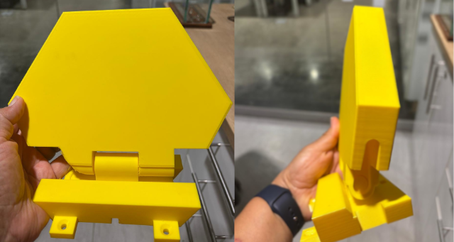
I redesigned the top and I've got a mobile desing and 3D printed it, like show in the following photos
I also designed the Stepper Motor case like show in the following photos
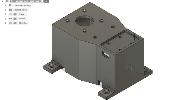
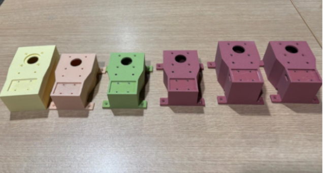
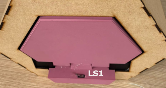
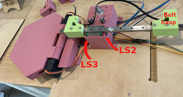
I've have to make several trials, due to dimensions that I did not consider at the begining,and that also to include to rectancular holes to incorporate the limit switches. But at the end, the final changes were made due to its high, because it need to be aligned with the mobile top. Like it can be observed in the following photo.
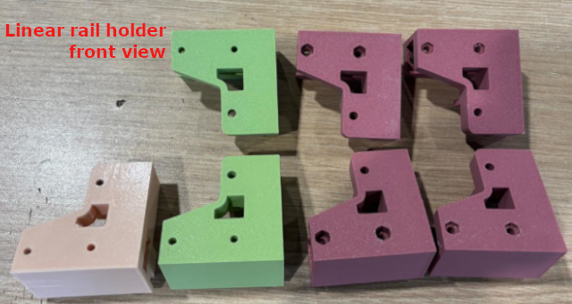
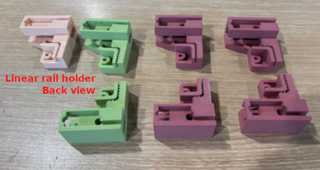
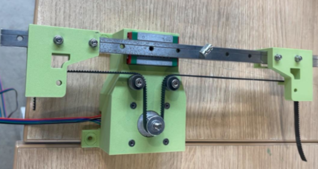
The third mechanical components are the pair of the linear rail's belt holders. I have made several trials, mostly because I need to adequately place the hexs. You can see the different changes in the following photos that show front and back views of the holders.
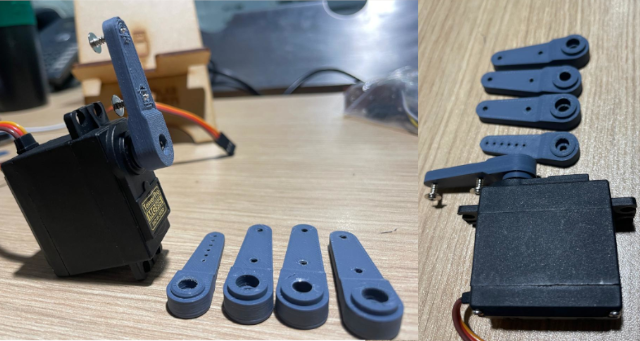
The final mechanical part are the pair of servo motors arms, because commercial design does not fit my design. I have made five trials due to length and width details, to adequately fit the servo and the top cavities.
I desinged and fabricated a rectangular platform that would be placed over the linear motion rail.
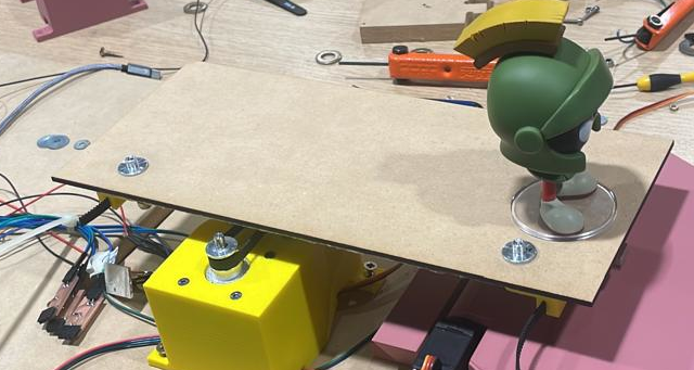
I also desinged and fabricated the shelf cover, posses two hexagonal sections and 5 rectangular pieces.
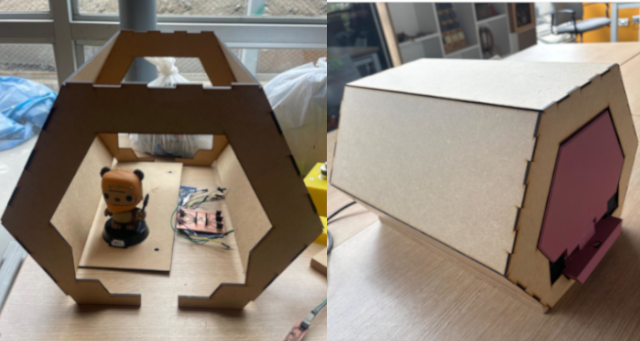
Finally, I desinged and fabricated the base of the shelf, 1 rectangular piece.

The following table provides details about the materials and components that I used.
| Quantity | Unit | Description | Origin | Cost (USD) |
|---|---|---|---|---|
| 1 | Kg | One 3d printing filament | China | 26.32 |
| 6 | Pieces | 3mm mdf (0.30x0.60 mm) | Chile | 4.74 |
| 1 | Piece | 15mm mdf piece (0.60x 0.80 mm) | Chile | 6.58 |
| 1 | Piece | 3mm Color Acrylic (0.30x0.60 mm) | Chile | 4.74 |
| 1 | Und | XIAO ESP32C3 | China | 5.92 |
| 2 | Und | MG995 Servos Motors | China | 13.16 |
| 3 | Und | Micro limit switch 3P SPDT 1A 125V AC | China | 1.58 |
| 1 | Und | Nema 17 Stepper Motor | China | 13.16 |
| 1 | Und | XL4015 5A Voltage and Current regulator | China | 6.58 |
| 1 | Und | Energy source 12V | China | 13.16 |
| 4 | Und | One terminal block 2x1 | China | 0.53 |
| 8 | Und | One terminal block 3x1 | China | 1.05 |
| 3 | Und | One terminal block 4x1 | China | 0.53 |
| 3 | Und | Resistors 1k | China | 0.39 |
| 1 | Und | DRV8428E driver | China | 9.21 |
| 1 | Und | Trimmer 10K | China | 1.32 |
| 1 | Und | Unpolarized capacitor 0.1 uF | China | 0.26 |
| 1 | Und | Polarized capacitor 100 uF | China | 1.32 |
| 1 | Und | Unpolarized capacitor 1 uF | China | 0.26 |
| 1 | Und | USB Type-C Connector | China | 6.58 |
| 1 | Und | 10 Amps 125 Volts AC Power Cord Cable for Electronics | China | 2.63 |
| 1 | Und | MGN12H 350mm Linear Rail 11.6 | USA | 31.58 |
| 4 | Und | 1/2 inch Bore Bearing: R8-2RS bearing size: Inner Diameter: 0.5 inches (12.7 mm); Outer Diameter: 1.125 inches (28.575 mm); Width: 0.3125 inches (7.938 mm) | USA | 6.32 |
| 1 | Und | GT2 Timing Belt Pulley,16 Teeth 5mm Bore Aluminum Timing Belt Pulley Tool for CNC | USA | 2.11 |
| 40 | cm | GT2 Belt 2mm Pitch 6mm Wide | USA | 1.10 |
| 2 | Und | M5 Metric Hex Head Socket Cap Bolt | China | 0.05 |
| 2 | Und | M5 Metric Hex Nut | China | 0.05 |
| 4 | Und | M3 Metric Hex Head Socket Cap Bolt | China | 0.11 |
| 4 | Und | M3 Metric Hex Nut | China | 0.11 |
| 4 | Und | M3 Metric Screw | China | 0.11 |
| 4 | Und | M3 Metric Nut | China | 0.11 |
| 4 | Und | M3 Self Drilling Screws for wood | China | 1.05 |
| 2 | Und | M8 Self Drilling Screws for wood | China | 1.05 |
| - | - | Dupont cables M-F | China | 0.66 |
| - | - | Dupont cables M-M | China | 0.66 |
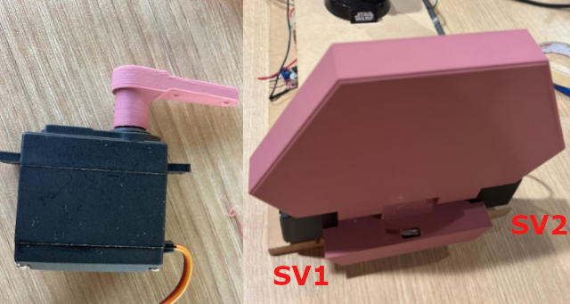
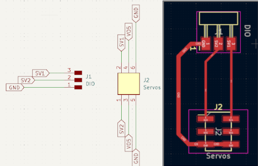
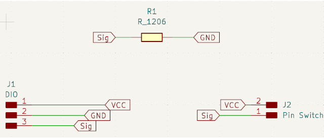
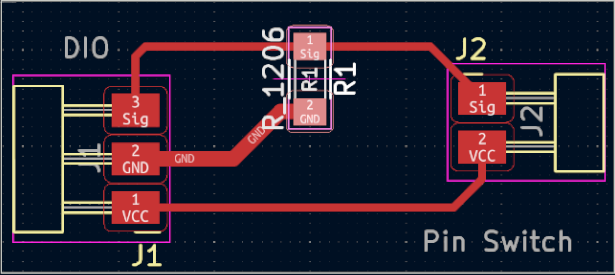
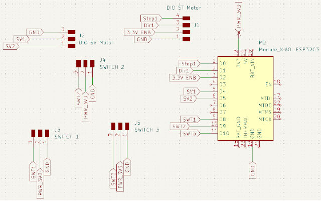
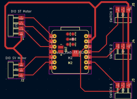
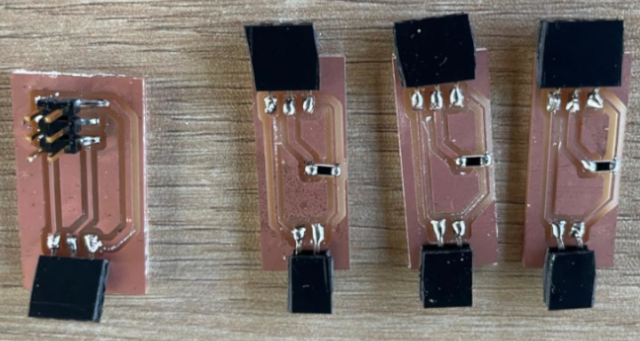
The following photo shows the 4 PCBs fabricated for the two servo motors (1st on the left) and 3 for the switches.
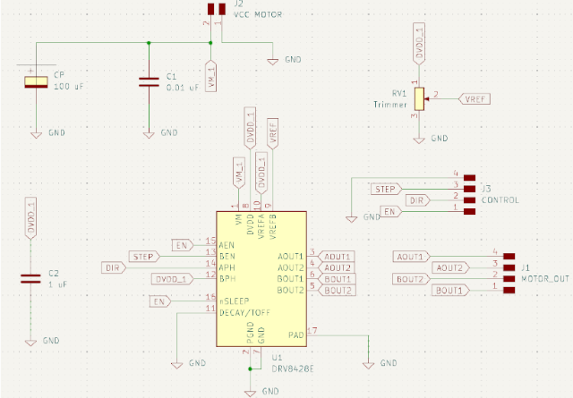
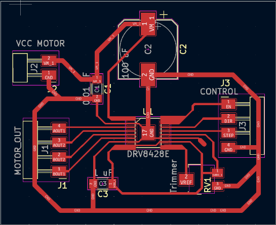
The following photo shows the PCBs fabricated for the stepper motor.
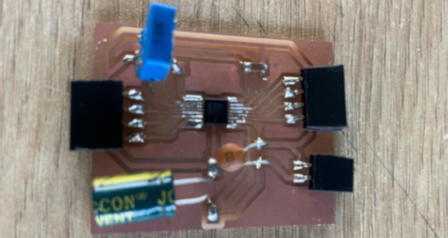
Finally the photo below shows the Main PCBs fabricated for XiaoESP32-C3.
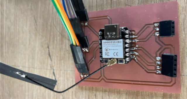
I made the program using Arduino IDE, which follow this schema integration, shown in the following
image.

Because the motion will be activated by bluethooth LightBlue App to send open and close action by
string. I'm not a complete exprt in programing, but the good thing is that I used the programs of in
my previous assigments, and to integrate them my instructors provide me a lot of support. First to
modified the servo motor program to make the movement in different direction at the same time. And
then to integrate the delays between the signals that provide the micro limit switches that allows
to activate and stop the stepper motor motion.
In this case, the open string to activate the system and open the door. Then the motor
gets in forward motion until reaching a limit switch that will stop the motor movement. The
close string will activate stepper motor backward motion until reach the next switch.
Finally, the order will be to acticate the servo motors backward motion to close the shelf.
At the begining I included the libraries needed (include bluethoot conexion and servos controller).
Then, I define the pins for steppers motors and switches, to declare the servo object.
The first and second void function includes the servo motor motion up to 90° to open
and close wiht 25s delay. The following two void function is to activate the stepper
motor motion forwards and backwards
After I include the information about the connection to bluethooht (adding the information that suggest Xiao). And then defining that the commnad that will received will be a string. The declaring what will happen with "open" string (open the door) and then declaring the movement with "close" string, each of then with 1000ms delay.
Then comes the part of the code that bring details about the servo motion with 50 hz and their connection with the stepper motor motion (where says "set pins"). Considering that the servos motion in different directions, this part of the coding declare the initial position of both. As you can see on start on 0° and the other one at 90°. At the end the network name connection is declare as "FabLab"
the code that I've used is the following one:
#include <BLEDevice.h>
#include <BLEUtils.h>
#include <BLEServer.h>
#include <ESP32Servo.h>
//StepperMotor
#define stepPin D0
#define dirPin D3
#define enaPin D2
#define stepsPerRevolution 200
//Switches
#define swIn D8
#define swOut D7
#define swOpen D9

Servo myservo1;
Servo myservo2;  // create servo object to control a servo
// 16 servo objects can be created on the ESP32
// Recommended PWM GPIO pins on the ESP32 include 2,4,12-19,21-23,25-27,32-33
// Possible PWM GPIO pins on the ESP32-S2: 0(used by on-board button),1-17,18(used by on-board LED),19-21,26,33-42
// Possible PWM GPIO pins on the ESP32-S3: 0(used by on-board button),1-21,35-45,47,48(used by on-board LED)
// Possible PWM GPIO pins on the ESP32-C3: 0(used by on-board button),1-7,8(used by on-board LED),9-10,18-21
#if defined(CONFIG_IDF_TARGET_ESP32S2) || defined(CONFIG_IDF_TARGET_ESP32S3)
int servoPin = 17;
#elif defined(CONFIG_IDF_TARGET_ESP32C3)
//Servomotors
int servoPin1 = D4; //
int servoPin2 = D5; //
#else
int servoPin = 18;
#endif

int statIn = 0;
int statOut = 0;
int statOpen = 0;

void openDoor(){
  myservo1.write(0);
  myservo2.write(90);
  delay(25);
}

void closeDoor(){
  myservo1.write(90);
  myservo2.write(0);
  delay(25);
}

void moveForward(){
  digitalWrite(stepPin, HIGH);
  delayMicroseconds(2000);
  digitalWrite(stepPin, LOW);
  delayMicroseconds(2000);
}

void moveBackward(){
  digitalWrite(stepPin, LOW);
  delayMicroseconds(2000);
  digitalWrite(stepPin, HIGH);
  delayMicroseconds(2000);
}

// Define the UUIDs for the BLE service and characteristics
#define SERVICE_UUID        "6698670f-5b28-4069-bcb1-9276ed443012"
#define CHARACTERISTIC_UUID "56caf526-b906-46b1-a4c9-9eef3ac8cbeb"

// BLE Server Callbacks
class MyCallbacks : public BLECharacteristicCallbacks {
	void onWrite(BLECharacteristic *pCharacteristic) {
		String value = pCharacteristic->getValue();

		if (value.length() > 0) {
			Serial.print("Received Value: ");
			for (int i = 0; i < value.length(); i++)
				Serial.print(value[i]);

			Serial.println();
			statIn = digitalRead(swIn);
			statOut = digitalRead(swOut);

			// Check for 'open' or 'close' commands
			if (value == "open") {
				openDoor();  // Open the door
				delay(1000);
				digitalWrite(dirPin, HIGH);
				do{
				  moveForward();
				  statIn = digitalRead(swIn);
				  Serial.println(statIn);
				}while(statIn != 1);
				Serial.println("Door Opened");
			} else if (value == "close") {
				digitalWrite(dirPin, LOW);
				do{
				  moveForward();
				  statOut = digitalRead(swOut);
				  Serial.println(statOut);
				}while(statOut != 1);
				delay(1000);
				closeDoor(); // Close the door
				Serial.println("Door Closed");
			}
		}
	}
};

void setup() {
	// Initialize Serial Monitor
	Serial.begin(115200);
	// Allow allocation of all timers
	ESP32PWM::allocateTimer(0);
	ESP32PWM::allocateTimer(1);
	ESP32PWM::allocateTimer(2);
	ESP32PWM::allocateTimer(3);
	myservo1.setPeriodHertz(50);    // standard 50 hz servo
	myservo2.setPeriodHertz(50);
	myservo1.attach(servoPin1, 500, 2500); // attaches the servo on pin 18 to the servo object
	myservo2.attach(servoPin2, 500, 2500);
	// using default min/max of 1000us and 2000us
	// different servos may require different min/max settings
	// for an accurate 0 to 180 sweep

	// Set pins
	pinMode(stepPin, OUTPUT);
	pinMode(dirPin, OUTPUT);
	pinMode(enaPin, OUTPUT);
	pinMode(swIn, INPUT);
	pinMode(swOut, INPUT);
	pinMode(swOpen, INPUT);

	//Initial conditions
	myservo1.write(90);
	myservo2.write(0);
	delay(25);
	digitalWrite(enaPin, HIGH);

	// Initialize BLE
	BLEDevice::init("FabLab");
	BLEServer *pServer = BLEDevice::createServer();
	BLEService *pService = pServer->createService(SERVICE_UUID);

	// Create a BLE characteristic
	BLECharacteristic *pCharacteristic = pService->createCharacteristic(
										 CHARACTERISTIC_UUID,
										 BLECharacteristic::PROPERTY_READ |
										 BLECharacteristic::PROPERTY_WRITE
									   );

	// Set the callback for receiving data
	pCharacteristic->setCallbacks(new MyCallbacks());
	pCharacteristic->setValue("Waiting for commands...");

	// Start the service
	pService->start();

	// Start advertising
	pServer->getAdvertising()->start();
	Serial.println("Waiting for a client to connect...");
}

void loop() {
	// Nothing to do here, waiting for BLE commands
}
Establish Cellphone connectivity with the microcontroller using the LightBlue App, that
you can dowload from AppStore (iphone) which recognise first the "FabLab" network that
the XiaoESP32-C3 send. The App provides at the begining a list of all available
networks, we need select it and click on Connect. Once connected we see
the network data.
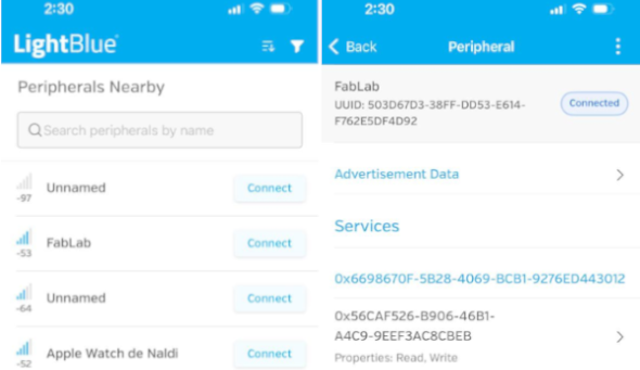
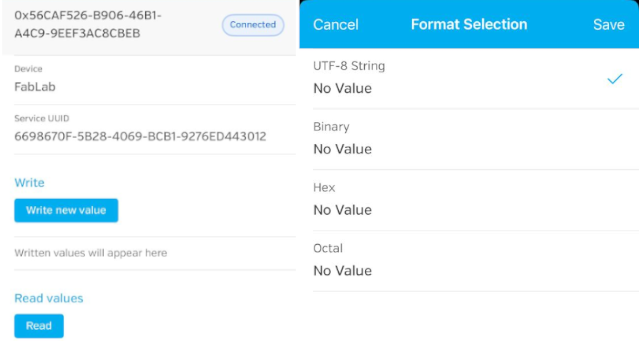
The following screen swill show two options write new value and
Read. We choose write new value and the app ask to select the
type of value. Here we need to choose UTF-8 String
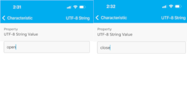
To activate the shelf motion we need to write open and to close it to write
close. You will notice that the time difference between open and close order
is one minute
Finally, you can download the fusion final design files in the following links:
Motorized Hidden Pop Up Shelf by Naldi Susan Carrion Puelles is licensed under CC BY-NC-ND 4.0