13. Networking and Communications
This week we worked on networking and communications. This is essentially the way of communicating between different devices, and it can get quite complex!
The group project for this week can be found here.
Designing a dual MCU, dual-sided board
For this week, I was stating to see the limitations of my audio development board V2, so I decided to make the V3!
For the V3, I wanted several things:
1. Power without USB through a barrel plug connector, to enable the device to work without connecting to USB, and with more than 5V (up to 18V)
2. Dual microcontrollers, to have essentially a dual core system for running realtime audio and processing data at the same time!
3. Majority of pins available on vertical connectors, along with ground and power on pinouts, for ease of wiring to other boards
4. Dual-sided board to avoid as much as possible 0-ohm resistors and to provide a ground plate in the back
5. Finding a simple wiring solution to connect to other boards.
6. Built-in RX and TX connection between the two boards (some issues with that, I will get into it)
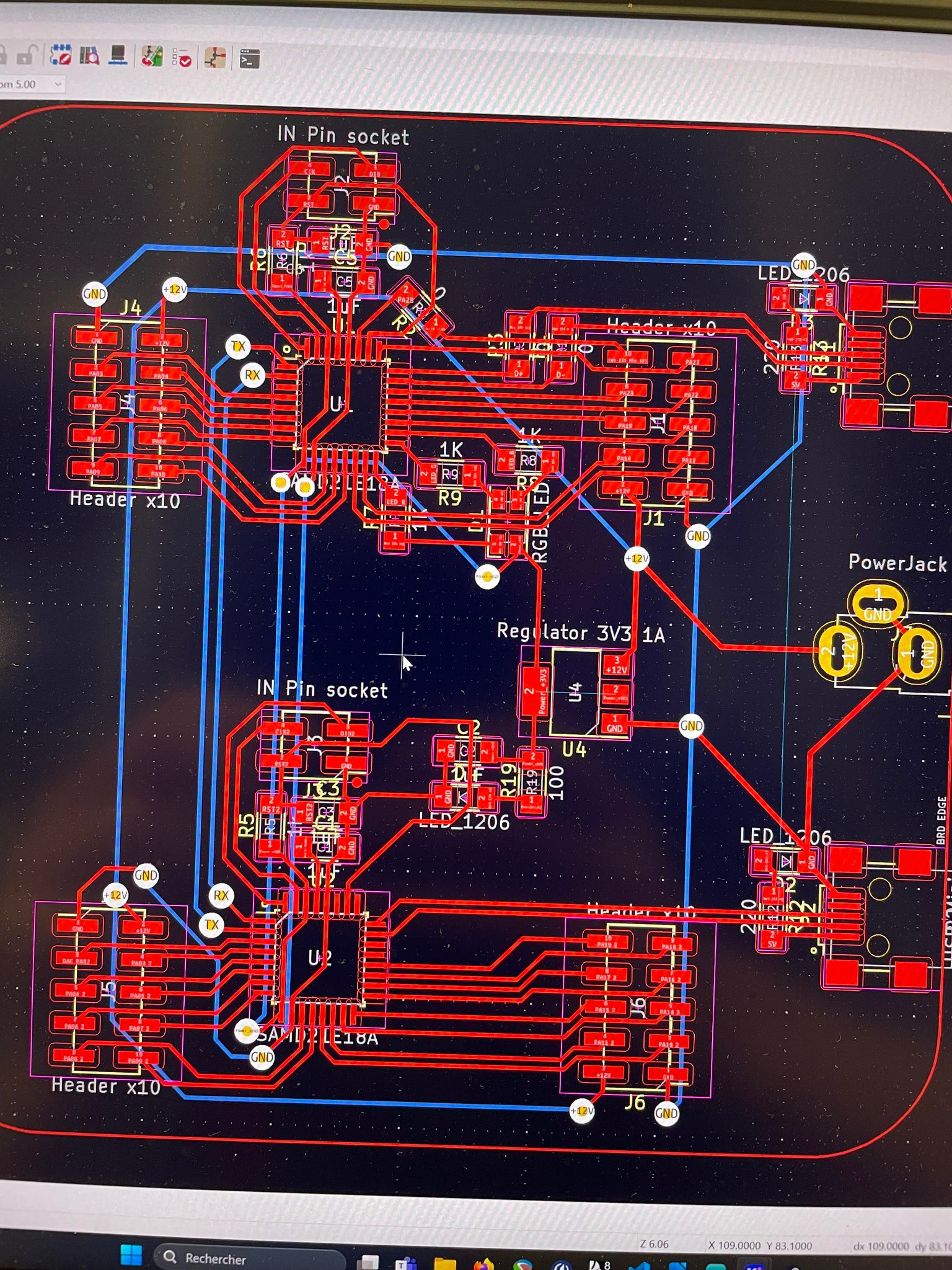
With all ths in mind, I designed my V3 board (which hopefully will be used for my final project!)
 Getting it to cut on both sides was a bit of a tricky process, but I managed it thanks to my friend Dani! who had done it before.
Essentially, the process is the same as cutting a one-sided board, with the addition of the following steps:
1. In Inkscape, adding a group for the backside traces and adding two holes in the middle vertically
2. Mirroring the backside traces and the outline cut horizontally
3. When cutting, place two pins with the heads cut off into the sacrificial board through the two holes above, this gives a centered reference point for flipping the board around
4. Then flip the board over when cutting, making sure to align it on the holes on the two pins
5. When soldering, vias need to be added to make the connection between both sides through the holes
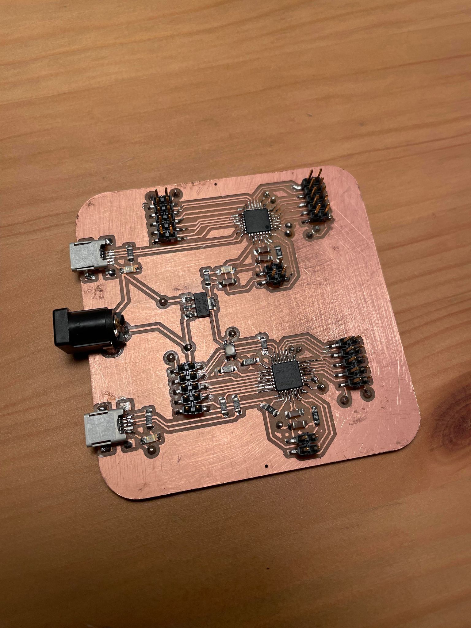
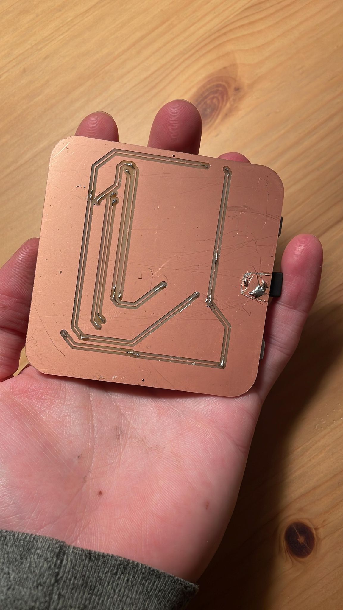
Here are the front and back sides of my V3 board:
Getting it to cut on both sides was a bit of a tricky process, but I managed it thanks to my friend Dani! who had done it before.
Essentially, the process is the same as cutting a one-sided board, with the addition of the following steps:
1. In Inkscape, adding a group for the backside traces and adding two holes in the middle vertically
2. Mirroring the backside traces and the outline cut horizontally
3. When cutting, place two pins with the heads cut off into the sacrificial board through the two holes above, this gives a centered reference point for flipping the board around
4. Then flip the board over when cutting, making sure to align it on the holes on the two pins
5. When soldering, vias need to be added to make the connection between both sides through the holes
Here are the front and back sides of my V3 board:
 The audio dev board V3 design files on KICAD can be found here!
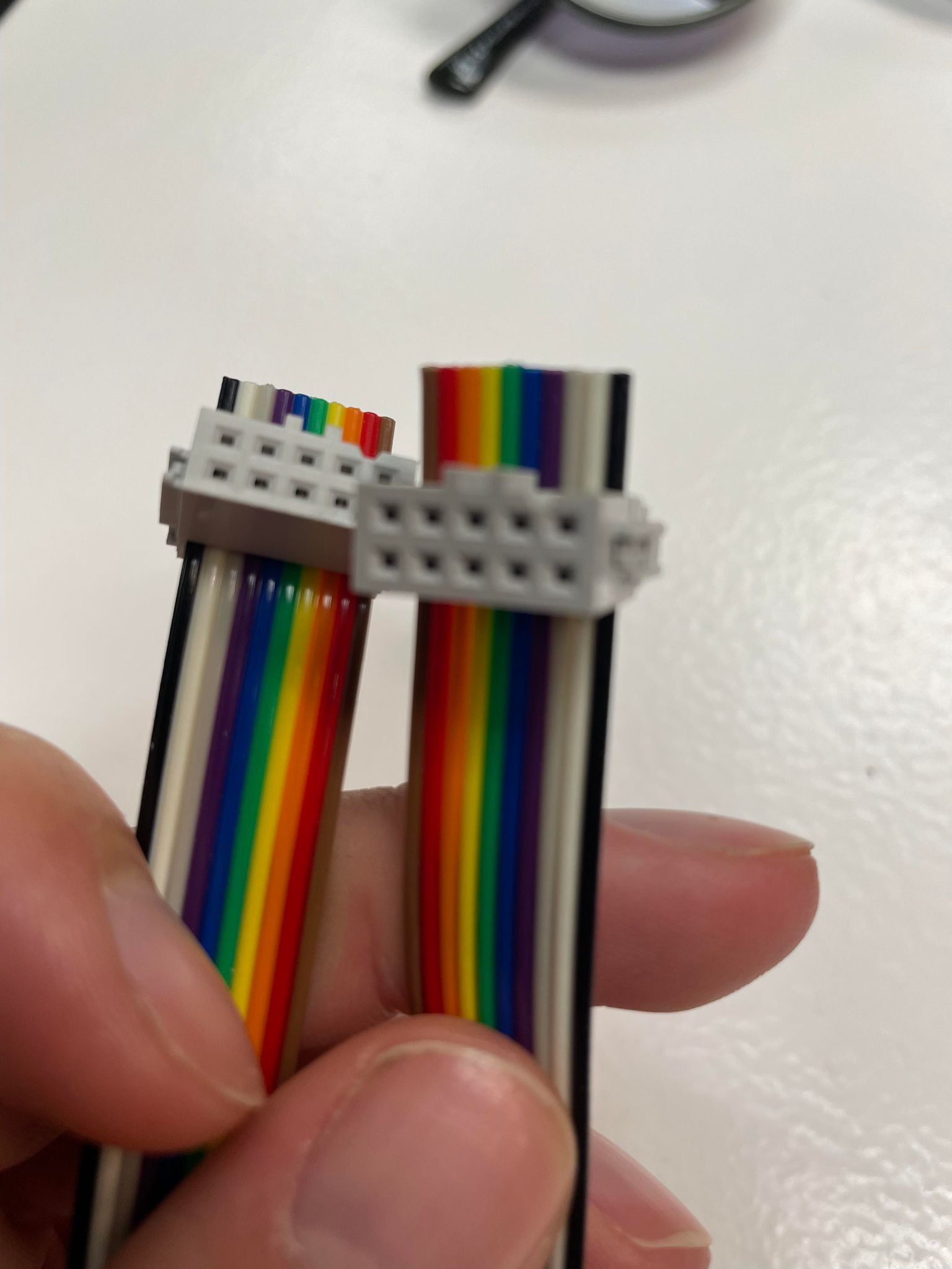
I also made some cables to be able to connect the 10 pin (2x5pins) connectors to other boards
The audio dev board V3 design files on KICAD can be found here!
I also made some cables to be able to connect the 10 pin (2x5pins) connectors to other boards
 I then got to work on the weekly assignment.
Weekly assignment
For this week's assignment, I chose to use I2C communication, as it allows a parent-child relationship with set addresses for each child.
For a first try at this, I set up the Barduino board to send a message to my board every time its Boot button was pressed, so when the button was pressed it would send HIGH, and when it was not it would send LOW.
The code for this assignment can be found here for the child ESP32 and here for the parent SAMD21.
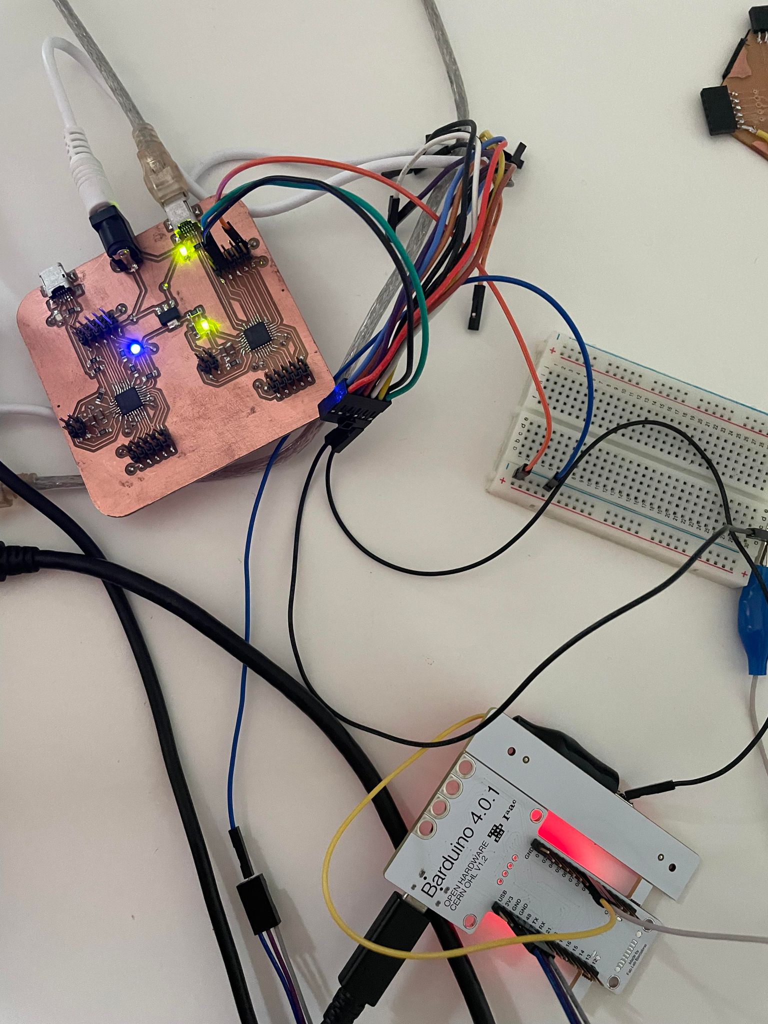 I then wanted to set up the built-in serial communication to go between the two samd21 boards, so that when the parent above received the button high message from the ESP32, it would send a serial message to the other SAMD21, which would switch its RGB LED to another colour.
After a few hours trying unsucesfully, I started diving deeper into the SAMD21 configuration files, and realised that PA00 and PA01 (which I had set as my RX and TX ports), are not configured like that in the bootloader I had set up.
Annoyingly, they are specified as SERCOM-ALT ports in the SAMD datasheet. The answer would have to be to change the SAMD21 config files...
I tried some basic steps which did not work, and resorted to asking on the Mattermost channel.
There I found help from Leo Kuipers, and have not yet worked through this problem, but am confident I will manage it!
This is at the moment still an ongoing problem... let's see if I can solve it!
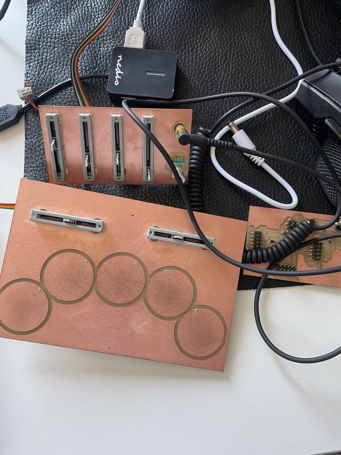
I also made a more advanced i2C connection as part of my final project, which senses capacitive pads as they are pressed and sends the pad number pressed to another board controlling a sound synthesis algorithm.
This is shown in the videos below, first video where I get the pad information with capacitive touch, and the second video showing it integrated in a crude box and making sound!
I then wanted to set up the built-in serial communication to go between the two samd21 boards, so that when the parent above received the button high message from the ESP32, it would send a serial message to the other SAMD21, which would switch its RGB LED to another colour.
After a few hours trying unsucesfully, I started diving deeper into the SAMD21 configuration files, and realised that PA00 and PA01 (which I had set as my RX and TX ports), are not configured like that in the bootloader I had set up.
Annoyingly, they are specified as SERCOM-ALT ports in the SAMD datasheet. The answer would have to be to change the SAMD21 config files...
I tried some basic steps which did not work, and resorted to asking on the Mattermost channel.
There I found help from Leo Kuipers, and have not yet worked through this problem, but am confident I will manage it!
This is at the moment still an ongoing problem... let's see if I can solve it!
I also made a more advanced i2C connection as part of my final project, which senses capacitive pads as they are pressed and sends the pad number pressed to another board controlling a sound synthesis algorithm.
This is shown in the videos below, first video where I get the pad information with capacitive touch, and the second video showing it integrated in a crude box and making sound!
 The code for this can be found Here for the parent pads board and here for the sound generation child!
The code on the parent side essentially checks which pad is pressed using the Adafruit Freetouch library, and then sends the pad number of that pad over i2C to the child board through the wire library.
Once the pad is not pressed anymore (no pad is pressed), it sends a note off.
On the child side, the code checks which pad is being pressed through the i2C reception, and uses that to determine a frequency to play on the synth.
Final project info including board design files and more can be found here!
The code for this can be found Here for the parent pads board and here for the sound generation child!
The code on the parent side essentially checks which pad is pressed using the Adafruit Freetouch library, and then sends the pad number of that pad over i2C to the child board through the wire library.
Once the pad is not pressed anymore (no pad is pressed), it sends a note off.
On the child side, the code checks which pad is being pressed through the i2C reception, and uses that to determine a frequency to play on the synth.
Final project info including board design files and more can be found here!