Week 9. Output Devices
The code for this week can be found here!
This week we worked on output devices.
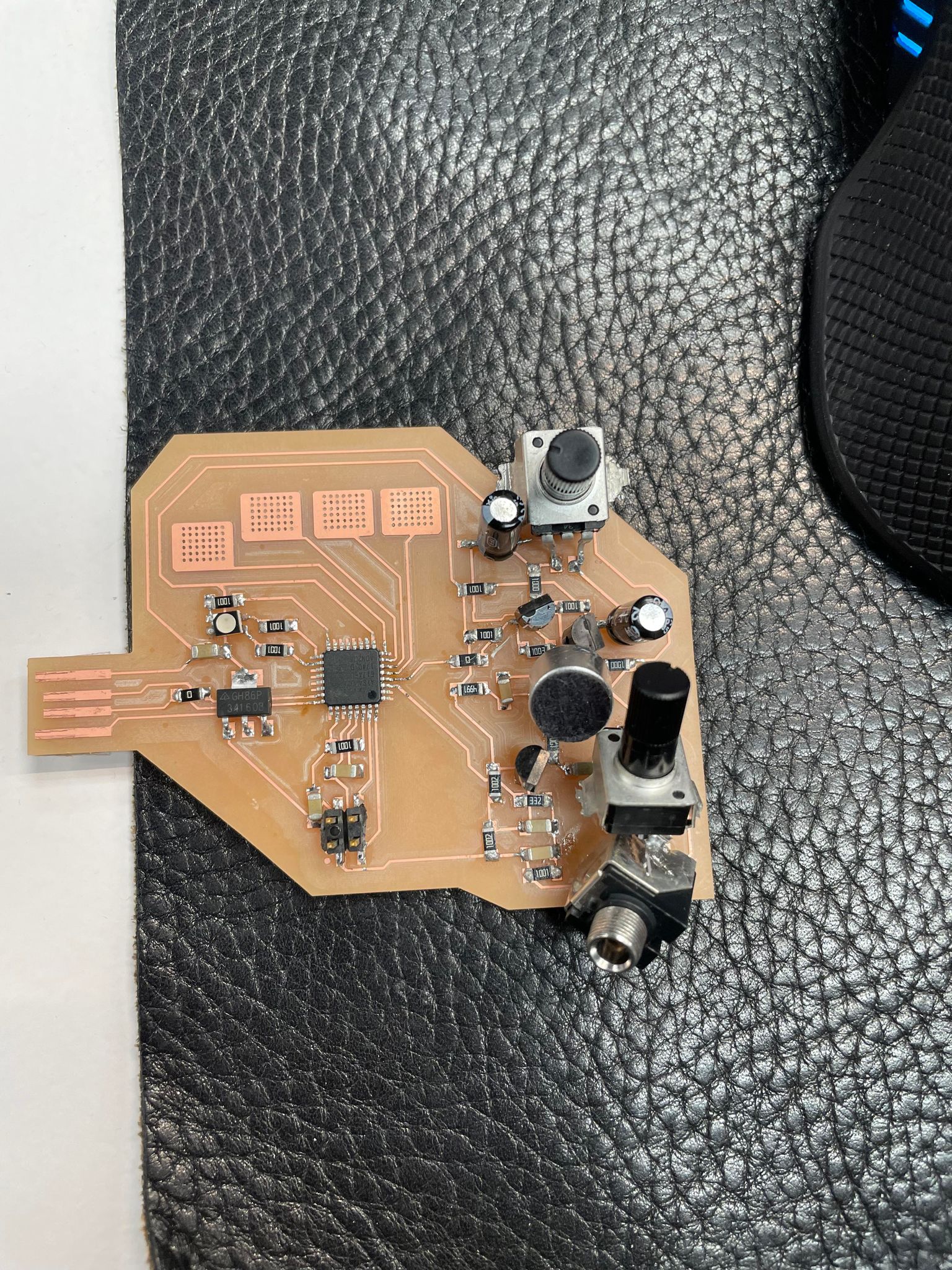
I remade my development board from last week into a new one that was much more modular.
This is last week's board:
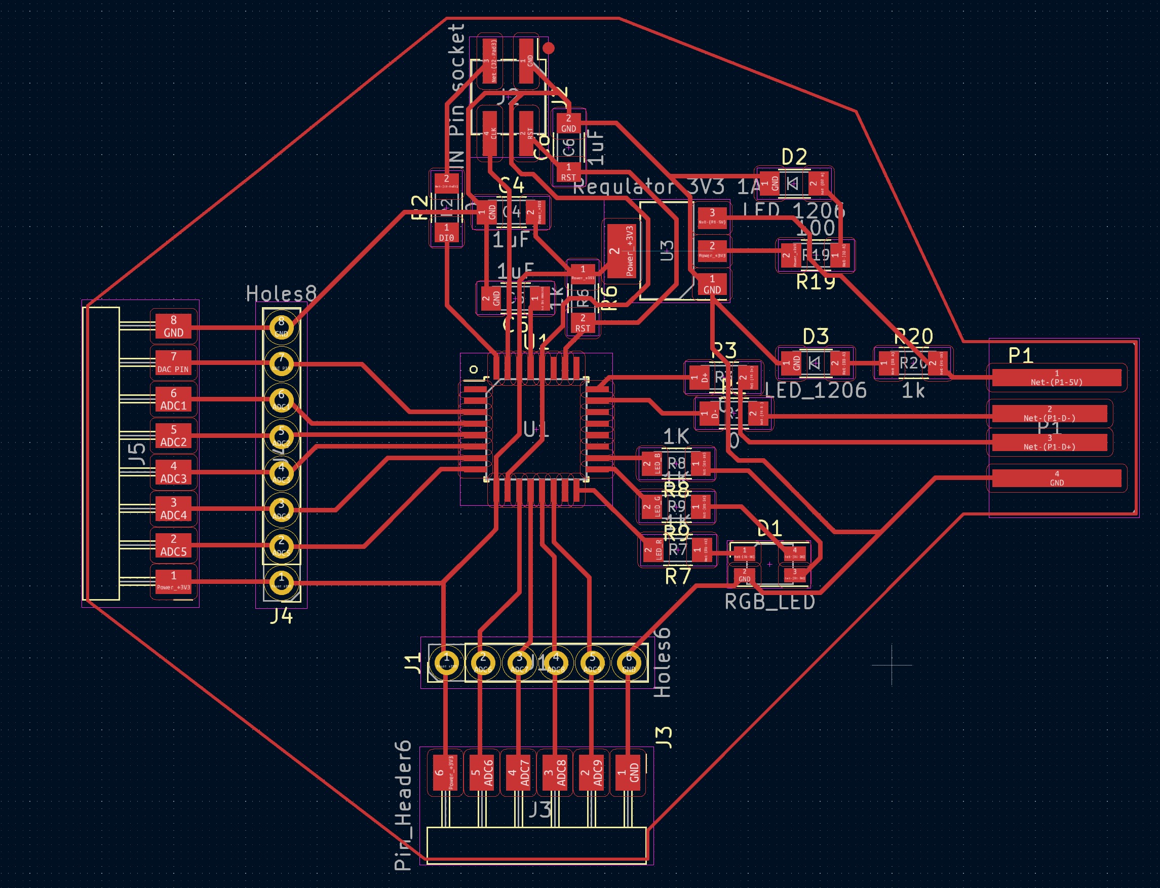
 And this week's new board PCB design:
 The files for the board as well as the various daughter boards can be found here!
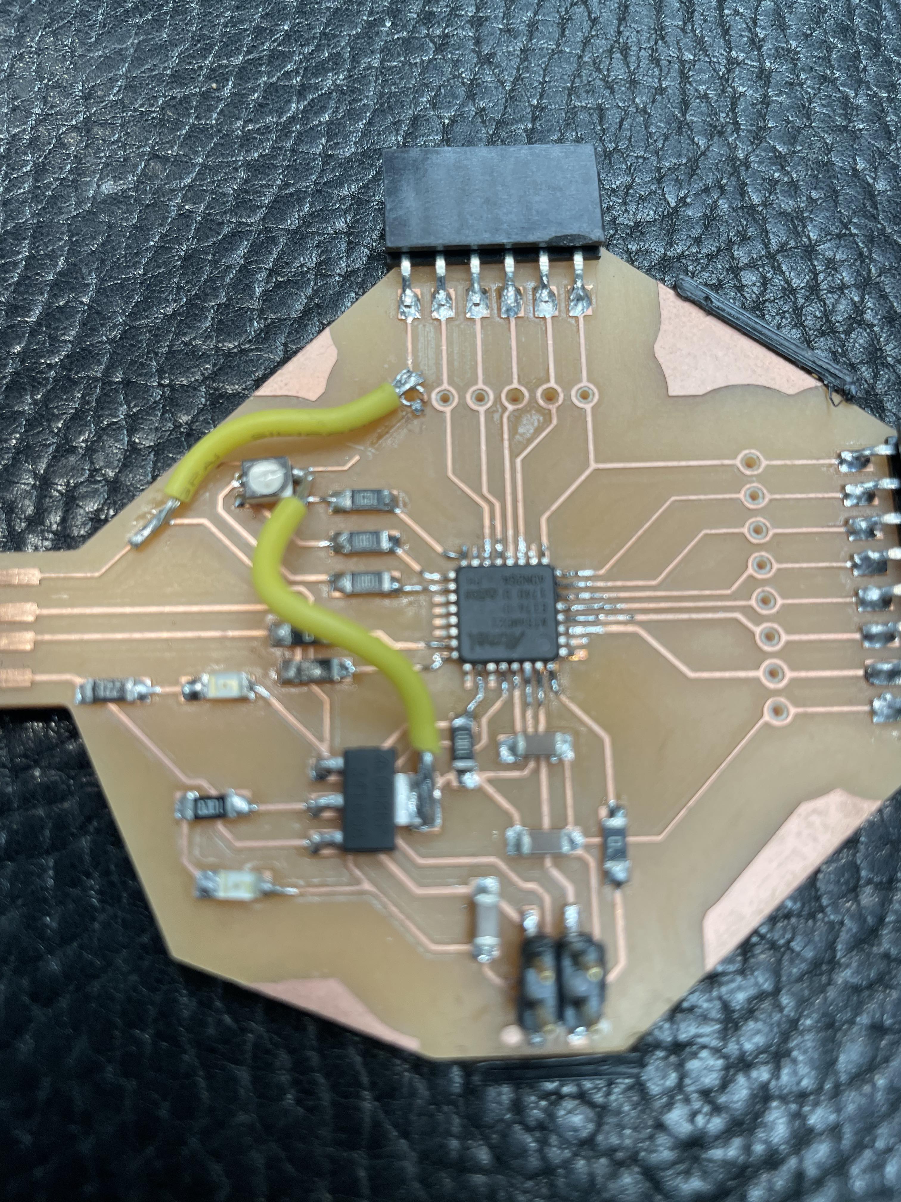
The new board incorporates the same USB, flashing and RGB LED, but has two added LEDs, on powered directly from the USB 5V and the other one powered by the 3.3V of the power regulator.
The rest of the board is just headers to connect to other boards.
The files for the board as well as the various daughter boards can be found here!
The new board incorporates the same USB, flashing and RGB LED, but has two added LEDs, on powered directly from the USB 5V and the other one powered by the 3.3V of the power regulator.
The rest of the board is just headers to connect to other boards.
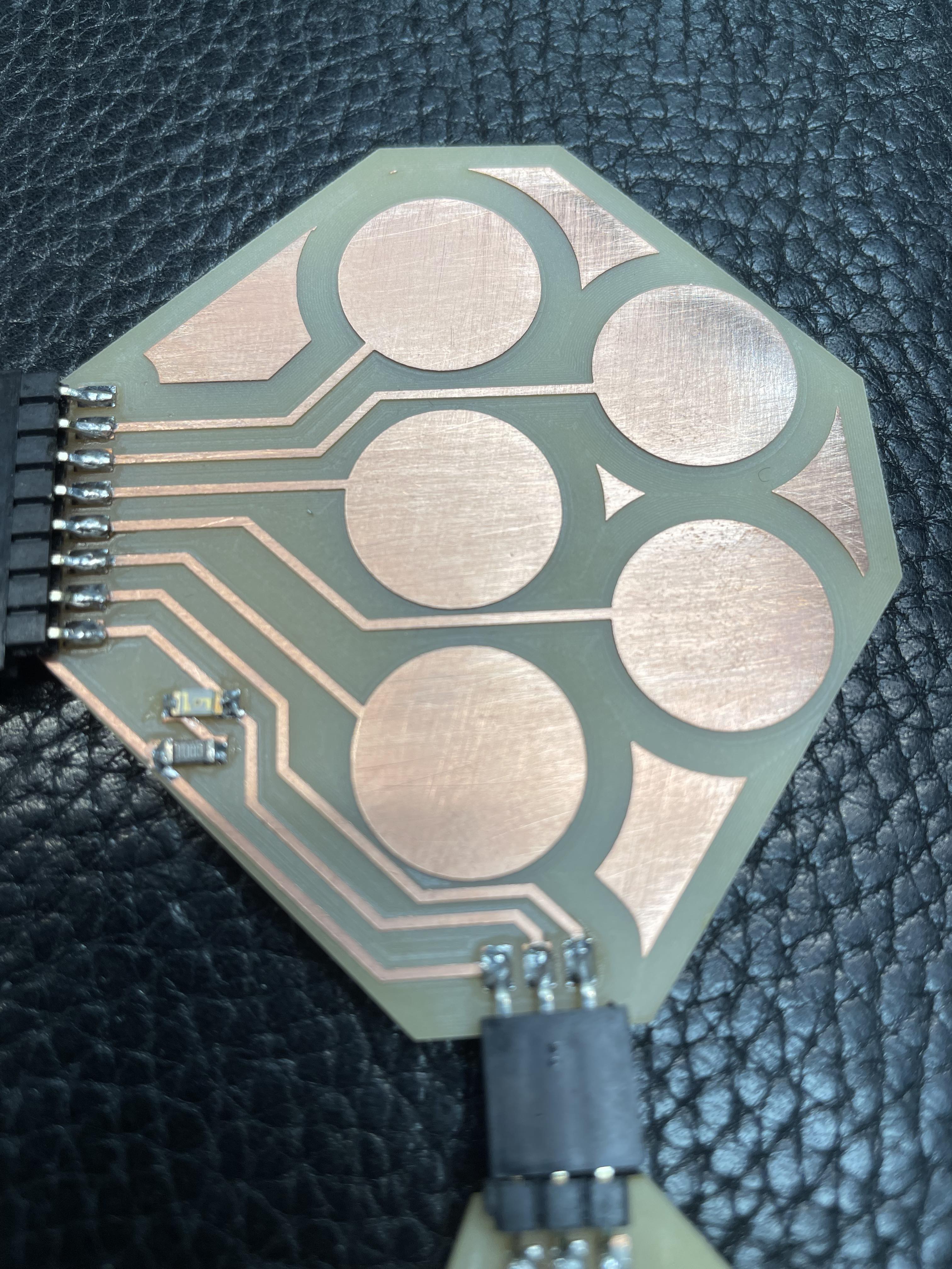
 The first other board I made includes some capacitive touch pads in order to get some touch readings.
 I then made an audio output section, which is a very basic 3.5mm jack output with a 10K ohm potentiometer, to regulate the signal level. The file for this can be found here in the output section.
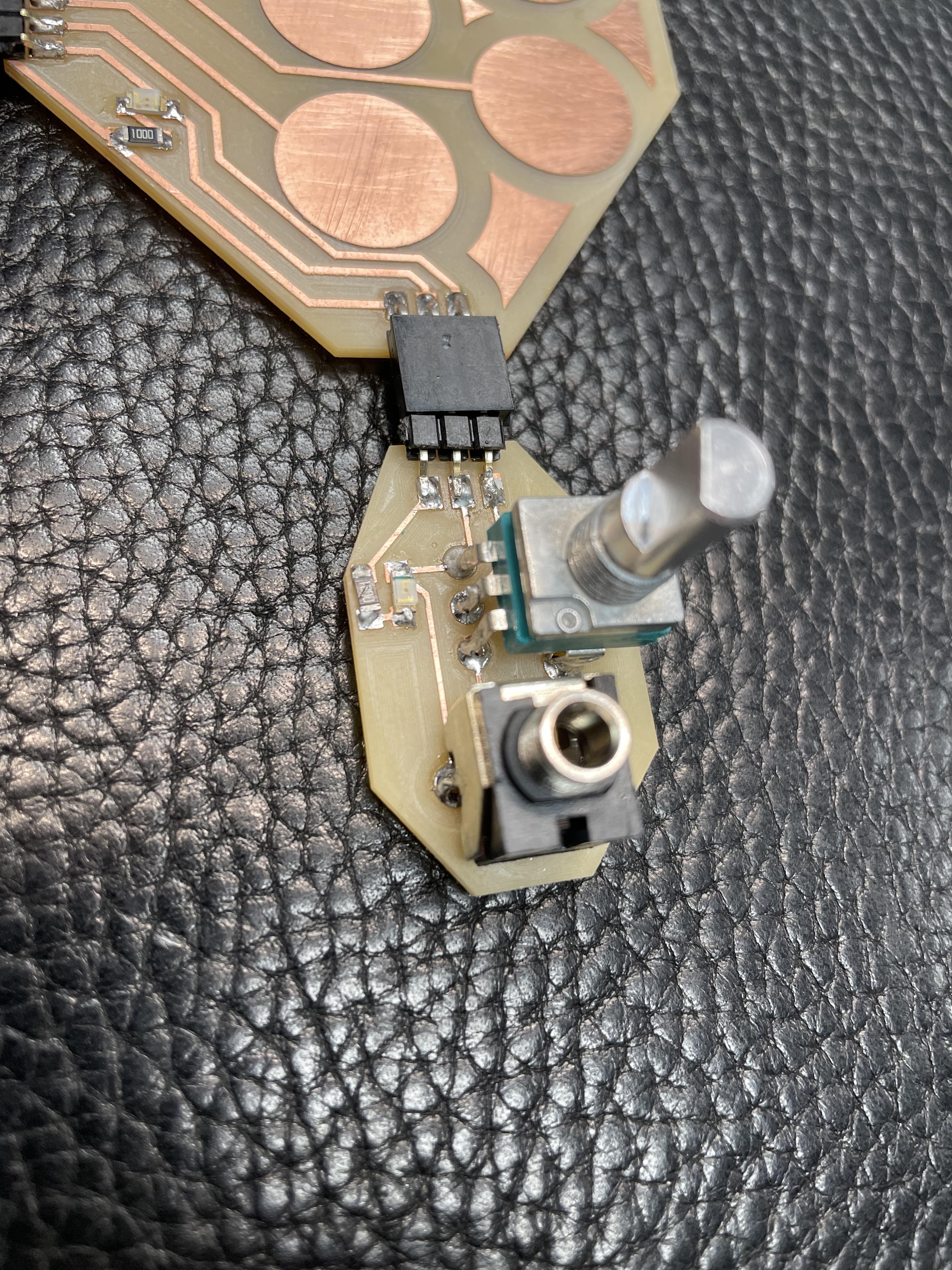 All the different boards have LED lights which are connected directly to power and ground, so they indicate when the board is plugged in.
Once put together, and with a lot of borrowing from Quentin Bolsee, I managed to output a simple square wave and change the RGB LED colour when pushing the pads!
Here is the code explanation:
First defining all the different aspects:
I include the Adafruit Freetouch library, which is a retro-engineered and open-source version of Atmel's QTouch library for capacitive touch on SAMD boards.
The 3 LEDs for the RGB LED.
Then the output (using pin 2)
Then N_PAD is jus the number of pads being used.
PAD_THRESH is the detection threshold for the capacitive touch of the pads.
Then I define an array with different frequency values for each pad, as well as the pins of the pads themselves, 3 through 7.
Next I initiate the Adafruit freetouch array with the pad number
I then set values for the RGB LED according to each pad, so touching the pads will turn the LED on in different ways.
I set up my LED function, compensating for the blue LED reduced brightness by halving the red and green values (note I could also have done this in hardware with a lower value resistor on the blue LED.)
In the setup function, I initialise everything, Serial, then the RGB LED and my pin 2 output.
I also initialise the pads using the freetouch library, with oversampling 4x, and a 50k internal resistor value.
Next the loop function.
I first set a debug mode to run only if debug is defined at the top.
This goes through the pads and writes their values to serial, can be useful for checking the detection threshold and whether all the pads are detected correctly.
I then check which pad is being triggered, by checking if the value of each pad in turn is above the threshold level (which occurs when capacitive touch is activated).
I use two variables called i_trig and i_trig_new, if the value of a pad is above the threshold, i_trig_new is equal to that pad number.
If i_trig_new is different from i_trig, I then set i_trig = to i_trig_new and turn on the RGB LED according to that pad number, and then output the frequency through Arduino's built-in tone generator.
The tone generation library works by sending a square wave through a pin at a certain frequency, turning that pin high and low which will output that frequency as an audible sound.
If no pads are pushed, i_trig will be = to -1, and this will turn off the tone and turn off the RGB LED.
All the different boards have LED lights which are connected directly to power and ground, so they indicate when the board is plugged in.
Once put together, and with a lot of borrowing from Quentin Bolsee, I managed to output a simple square wave and change the RGB LED colour when pushing the pads!
Here is the code explanation:
First defining all the different aspects:
I include the Adafruit Freetouch library, which is a retro-engineered and open-source version of Atmel's QTouch library for capacitive touch on SAMD boards.
The 3 LEDs for the RGB LED.
Then the output (using pin 2)
Then N_PAD is jus the number of pads being used.
PAD_THRESH is the detection threshold for the capacitive touch of the pads.
Then I define an array with different frequency values for each pad, as well as the pins of the pads themselves, 3 through 7.
Next I initiate the Adafruit freetouch array with the pad number
I then set values for the RGB LED according to each pad, so touching the pads will turn the LED on in different ways.
I set up my LED function, compensating for the blue LED reduced brightness by halving the red and green values (note I could also have done this in hardware with a lower value resistor on the blue LED.)
In the setup function, I initialise everything, Serial, then the RGB LED and my pin 2 output.
I also initialise the pads using the freetouch library, with oversampling 4x, and a 50k internal resistor value.
Next the loop function.
I first set a debug mode to run only if debug is defined at the top.
This goes through the pads and writes their values to serial, can be useful for checking the detection threshold and whether all the pads are detected correctly.
I then check which pad is being triggered, by checking if the value of each pad in turn is above the threshold level (which occurs when capacitive touch is activated).
I use two variables called i_trig and i_trig_new, if the value of a pad is above the threshold, i_trig_new is equal to that pad number.
If i_trig_new is different from i_trig, I then set i_trig = to i_trig_new and turn on the RGB LED according to that pad number, and then output the frequency through Arduino's built-in tone generator.
The tone generation library works by sending a square wave through a pin at a certain frequency, turning that pin high and low which will output that frequency as an audible sound.
If no pads are pushed, i_trig will be = to -1, and this will turn off the tone and turn off the RGB LED.