11. Input Devices
For this week we were tasked with measuring an input device connected to a board we have made. Since I was a bit busy with making an amplified speaker for some of the week, I decided to work with potentiometers on a basic FM synth, using a new (to me) library, Mozzi.
Group Assignment
The group assignment for this week can be found here!
How a potentiometer works
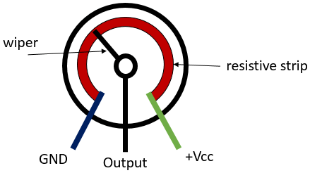
A potentiometer works as a variable voltage divider, connected on one end to ground, the other end to power, and in between to a wiper that runs across a resistive strip.
As you turn the wiper (the knob part), it changes the resistance on both sides, making it less one the side you are turning towards and more on the side you are turning away from.
You then receive a reading that is somewhere between VCC and ground, depending on the position of the wiper.
You can of course connect the potentiometer in other ways, in an analog circuit, to use as a variable voltage divider without being connected directly between VCC and ground.
Potentiometers and Mozzi Lib
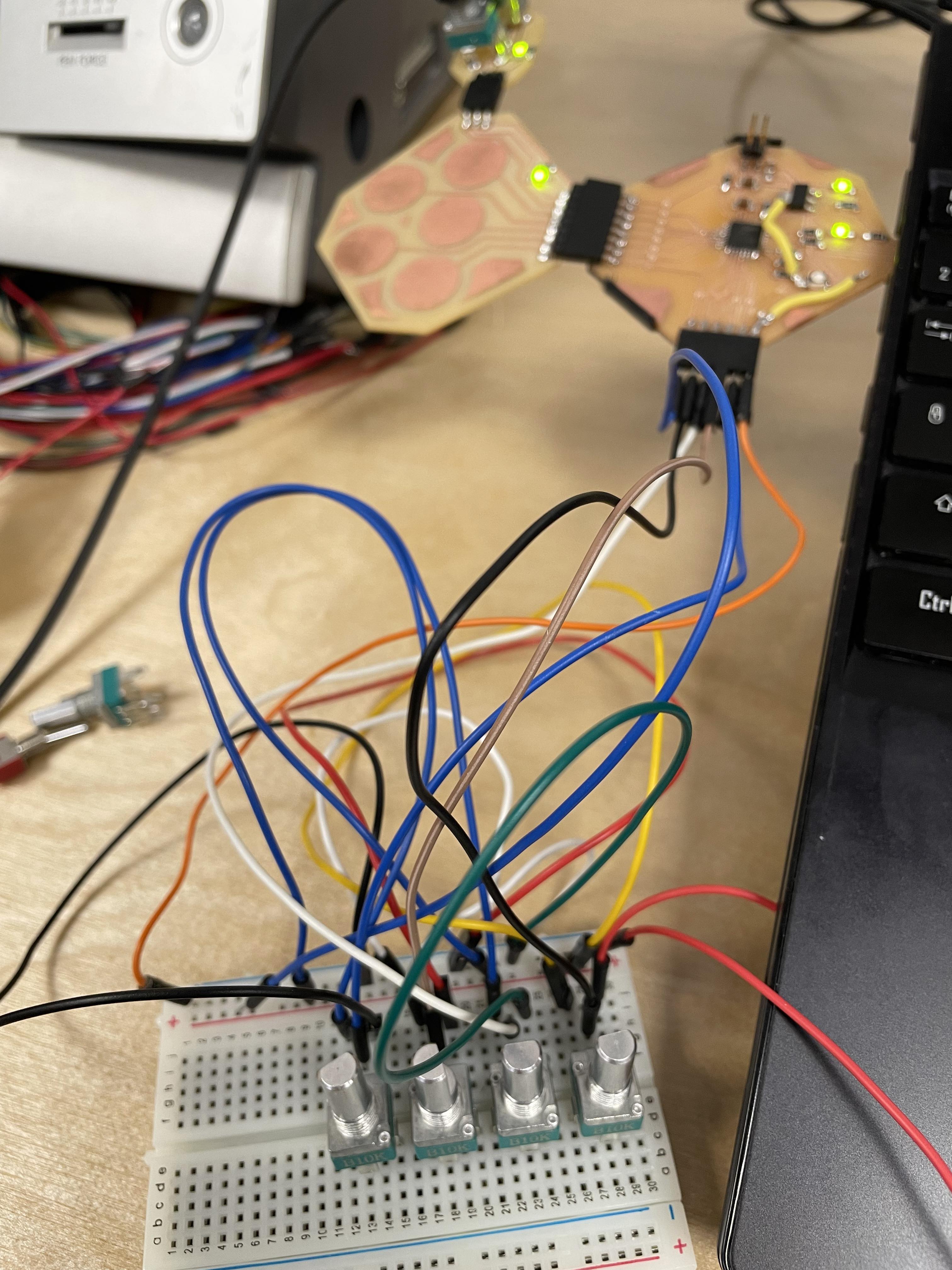
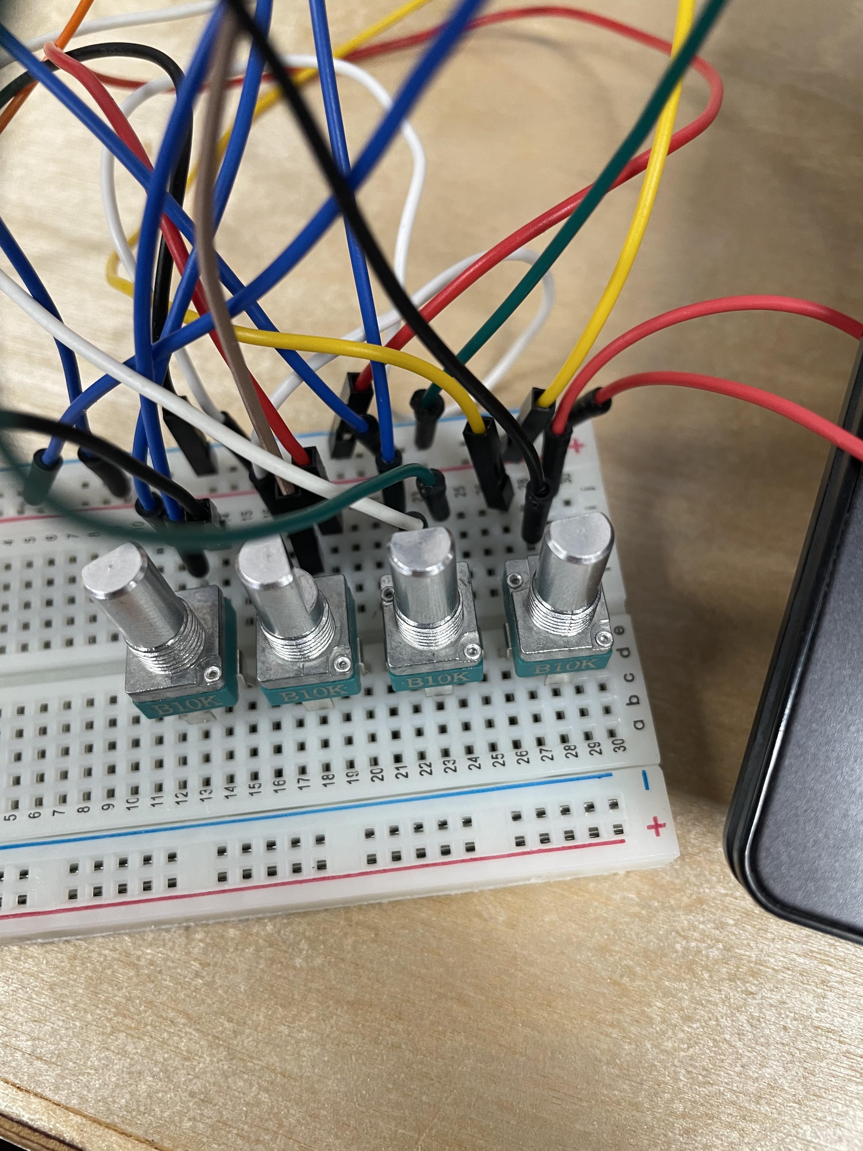
I set up the potentiometers on a breadboard and connected pin 1 to ground, pin 3 to power through the microcontroller, and pin 2 to an input pin on my SAMD21.
The result looked like this.
 Using one of the very slightly modified example codes from the Mozzi library, I then ran a simple FM synth on the SAMD21, controlling different parameters with the potentiometers. The library automatically routed the audio output to the DAC pin of the SAMD21, which was very nice!
FM synthesis is interesting, and can be explained as follows:
It is (according to Wikipedia), a form of synthesis which uses a modulator to modulate (as its name implies) the frequency of a waveform. This can be used to create rather simple "synth" sounds, or much more complex bell-like or percussive tones.
The code for this can be found here
To explain the code a little bit:
The min and max carrier frequencies are the minimum and maximum frequencies of the carrier signal, which go down to 22hz and go up to 880hz (a concert A4).
These set a range for potentiometer on pin 8 to follow.
The following min and max values set a multiplier rate for the potentiometer on pin 11, which goes up in whole numbers from 1 to 10.
The next min and max intensity and mod speed values set the FM intensity and modulation speed, inverted to reverse the action of the potentiometers on pins 9 and 10.
Next is the min and max modulation speed.
All those values are then mapped to be read from the potentiometers (for carrier frequency read minimum as the minimum carrier frequency of 22hz, and maximum as the maximum carrier frequency of 880hz, etc.)
Then the 4 pots are assigned to be read on their respective pins.
I then set 3 oscillators, 2 for audio and 1 for control, using the cosine data tables included at the top of the code.
I can next define a mod_ratio which gets multiplied later into the audio, as well as the fm_intensity variable which will be used later.
We finally get into the setup portion of the code, where we are just starting SerialUSB (useful for debugging), as well as Mozzi (the library running the synthesis engine)
In the updateControl loop, we read all our potentiometers with a special function called mozziAnalogRead, this is a modified version of AnalogRead which allows us to read an analog input while audio is running in real-time without pausing or glitching the audio.
We also use the updateControl function to set all our audio equations that will affect the audio signal
After that, we have the updateAudio function, which takes the equations and finalises them into our MonoOutput variable which allows us to get an audio output.
We then run the audioHook in the loop function in order to send the audio output to the DAC (digital to analog converter), which gives us weird sounds, as seen below!
Here is a little video of the FM synth in action!
After making the breadboard prototype, I implemented the synth into two boards, a control board and a board containing sliders (linear potentiometers) and the sound output.
I remade the control board later to make it smaller and better suited to my final project!
Using one of the very slightly modified example codes from the Mozzi library, I then ran a simple FM synth on the SAMD21, controlling different parameters with the potentiometers. The library automatically routed the audio output to the DAC pin of the SAMD21, which was very nice!
FM synthesis is interesting, and can be explained as follows:
It is (according to Wikipedia), a form of synthesis which uses a modulator to modulate (as its name implies) the frequency of a waveform. This can be used to create rather simple "synth" sounds, or much more complex bell-like or percussive tones.
The code for this can be found here
To explain the code a little bit:
The min and max carrier frequencies are the minimum and maximum frequencies of the carrier signal, which go down to 22hz and go up to 880hz (a concert A4).
These set a range for potentiometer on pin 8 to follow.
The following min and max values set a multiplier rate for the potentiometer on pin 11, which goes up in whole numbers from 1 to 10.
The next min and max intensity and mod speed values set the FM intensity and modulation speed, inverted to reverse the action of the potentiometers on pins 9 and 10.
Next is the min and max modulation speed.
All those values are then mapped to be read from the potentiometers (for carrier frequency read minimum as the minimum carrier frequency of 22hz, and maximum as the maximum carrier frequency of 880hz, etc.)
Then the 4 pots are assigned to be read on their respective pins.
I then set 3 oscillators, 2 for audio and 1 for control, using the cosine data tables included at the top of the code.
I can next define a mod_ratio which gets multiplied later into the audio, as well as the fm_intensity variable which will be used later.
We finally get into the setup portion of the code, where we are just starting SerialUSB (useful for debugging), as well as Mozzi (the library running the synthesis engine)
In the updateControl loop, we read all our potentiometers with a special function called mozziAnalogRead, this is a modified version of AnalogRead which allows us to read an analog input while audio is running in real-time without pausing or glitching the audio.
We also use the updateControl function to set all our audio equations that will affect the audio signal
After that, we have the updateAudio function, which takes the equations and finalises them into our MonoOutput variable which allows us to get an audio output.
We then run the audioHook in the loop function in order to send the audio output to the DAC (digital to analog converter), which gives us weird sounds, as seen below!
Here is a little video of the FM synth in action!
After making the breadboard prototype, I implemented the synth into two boards, a control board and a board containing sliders (linear potentiometers) and the sound output.
I remade the control board later to make it smaller and better suited to my final project!
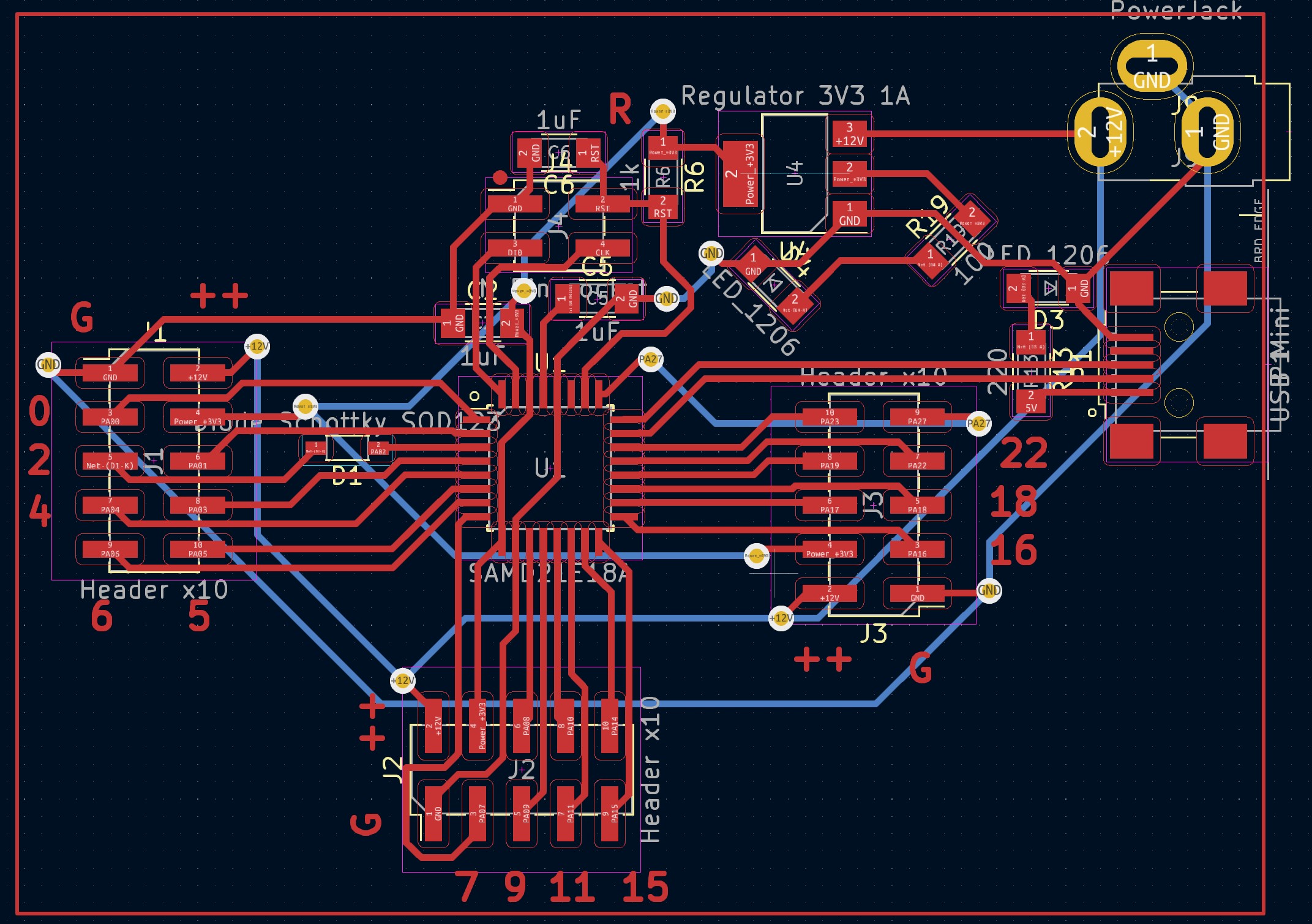
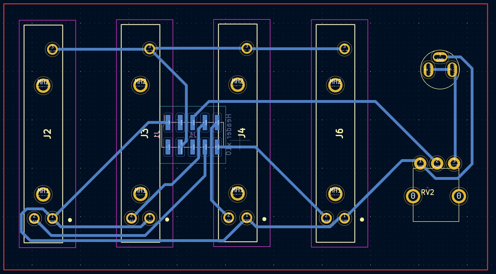 This board generally uses the same pins for outputs but has more available pins through headers as well as being able to be powered by a barrel plug instead of USB.
It is also double sided which makes it smaller and with more practical connections.
The files for fabricating these two boards can be found Here!
This board generally uses the same pins for outputs but has more available pins through headers as well as being able to be powered by a barrel plug instead of USB.
It is also double sided which makes it smaller and with more practical connections.
The files for fabricating these two boards can be found Here!