This week we worked on milling our first PCB (Printed circuit board) and soldering some basic components (LEDs, resistors, a button, a microcontroller and some headers).
I was particularly excited for electronics production as I have always wanted to design and make my own PCBs. While we did not get to design them (yet), we did get to use the Roland SRM-20 milling machines to cut the PCB blanks.
I've also soldered a lot the last few years and am quite familiar with electronics, so that part was not new and was quite easy for me.
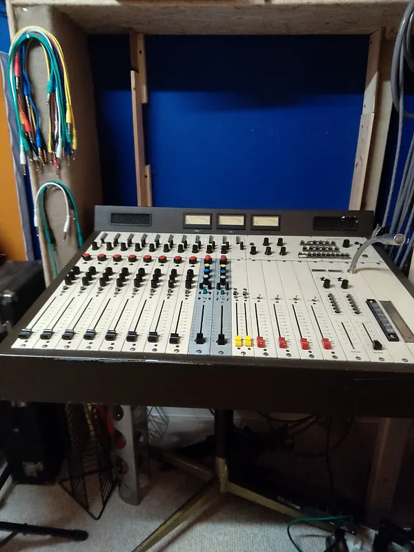
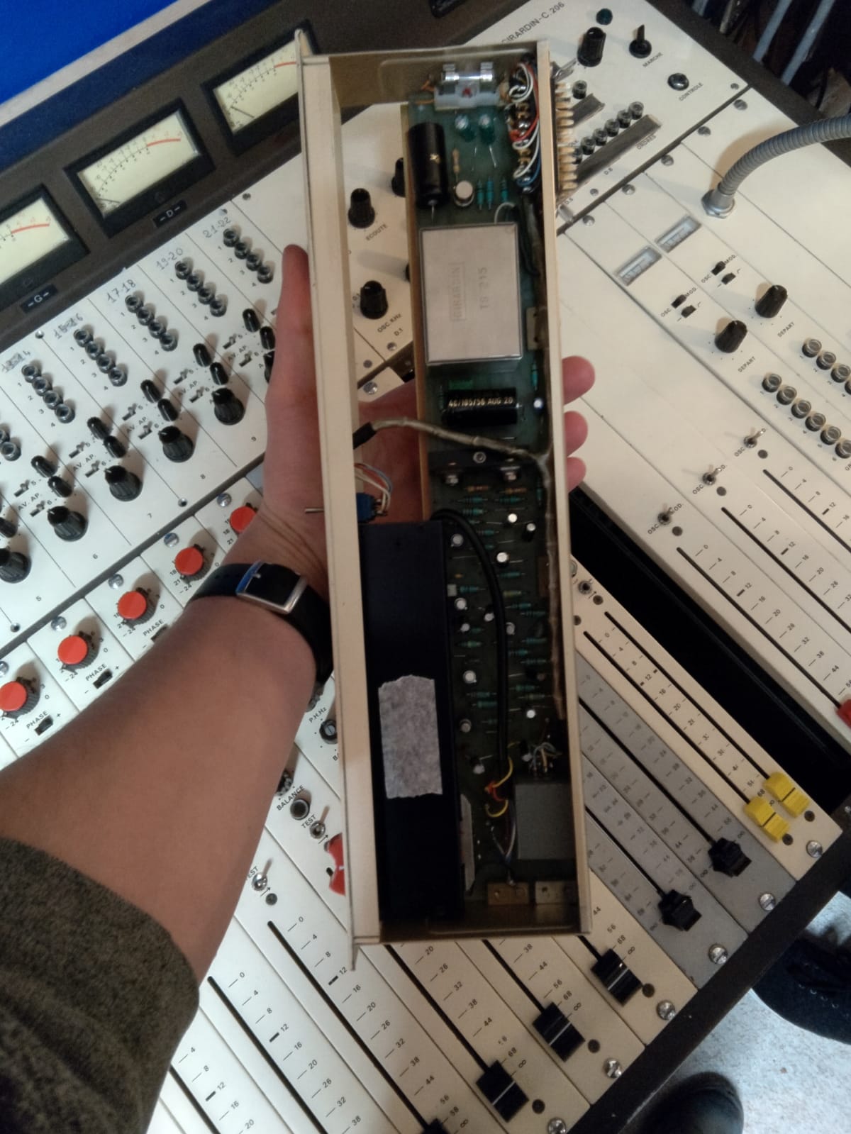
Fo example, I worked on an old French recording console, and switched out over 900 components for new ones!
Group Project
You can find the group project for this week here!
PCB Milling
First we learned about the milling machine (Roland SRM-20), and the different sized endmills we will be using.
The sizes are in Imperial units, and the common ones are 1/64" for milling the traces, and 1/32" for making holes and cutting around the PCB.
For the cutting speed, we generally use 3mm/s for traces (the actual connections between components, like cables), 1,5mm/s for holes, and 0,5mm/s for cutting the size of PCB we want from our blank board.
These are very fragile and we were warned several times to not drop them or touch the tips so as to not break them.
Luckily I managed to not break anything this time!
I first accessed the Mods Project Website, which can convert images to files for use with different machines, as well as connect directly to the machines.
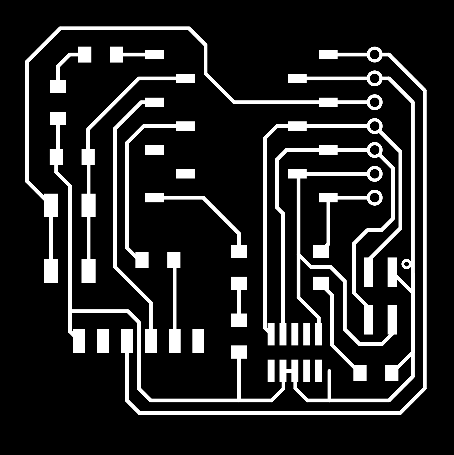
Then I uploaded the three images below (one by one), for Traces, Holes and Outline cut
In Mods, I had to set the following settings :
For traces and footprints: image at 1000dpi, 1/64 endmill selection, 3mm/s speed, at least 4 offsets (or set 0 to completely mill away the copper outside the traces and footprints), jog height at least 5mm for safety, origin set to 0 for all as the origin is set in the Roland machine software.
Aftewards, I checked the on/off switch to get the file out of the mods website, pressed calculate and voila !
I was then able to get a file to feed into the SRM-20 for PCB milling.
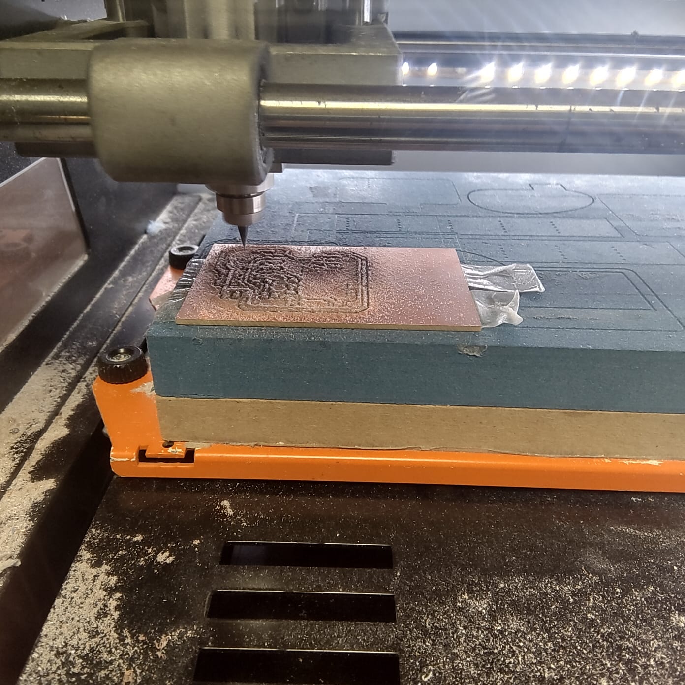
Before milling, it is necessary to prepare the machine, first loading a PCB blank with double sided tape, making sure it is as flat as possible.
Next, I attached the 1/64" endmill (being very careful not to drop it or touch the cutting part), calibrated the X/Y axis and the Z axis, and launched the milling!
Once the Traces was finished, I switched out the endmill for a 1/32", and made the holes and outline cut with that.
And that was the PCB done!
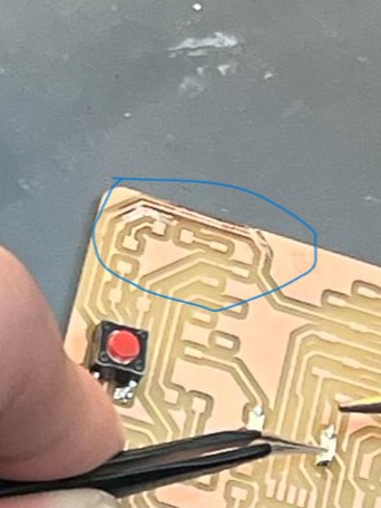
After milling the PCB, I realised the endmill had not gone deep enough in the top left corner.
To remedy the problem, I scratched away the copper with a small knife to make sure my traces were not connected.
I tested continuity with a multimeter and it all worked!
Soldering
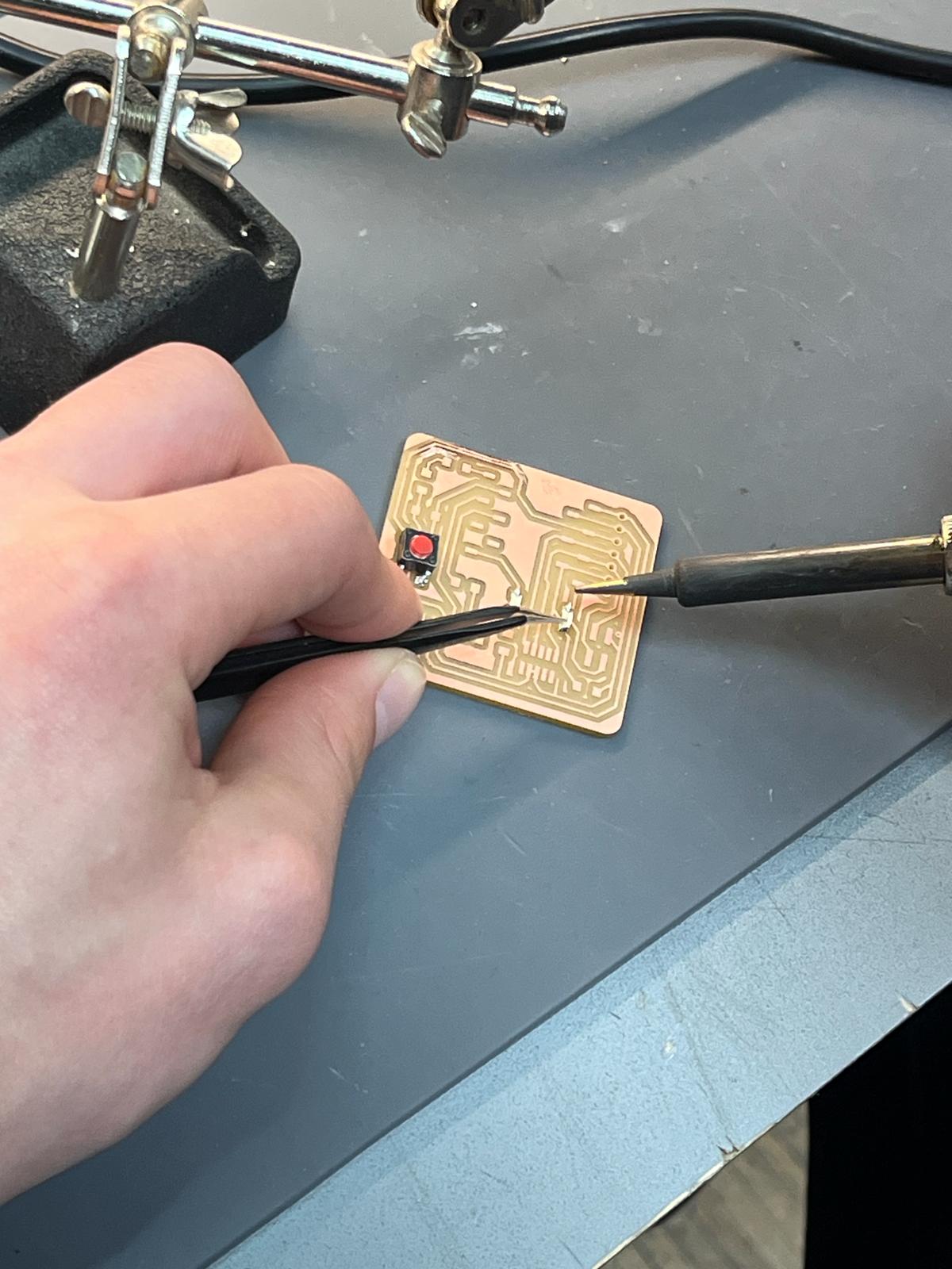
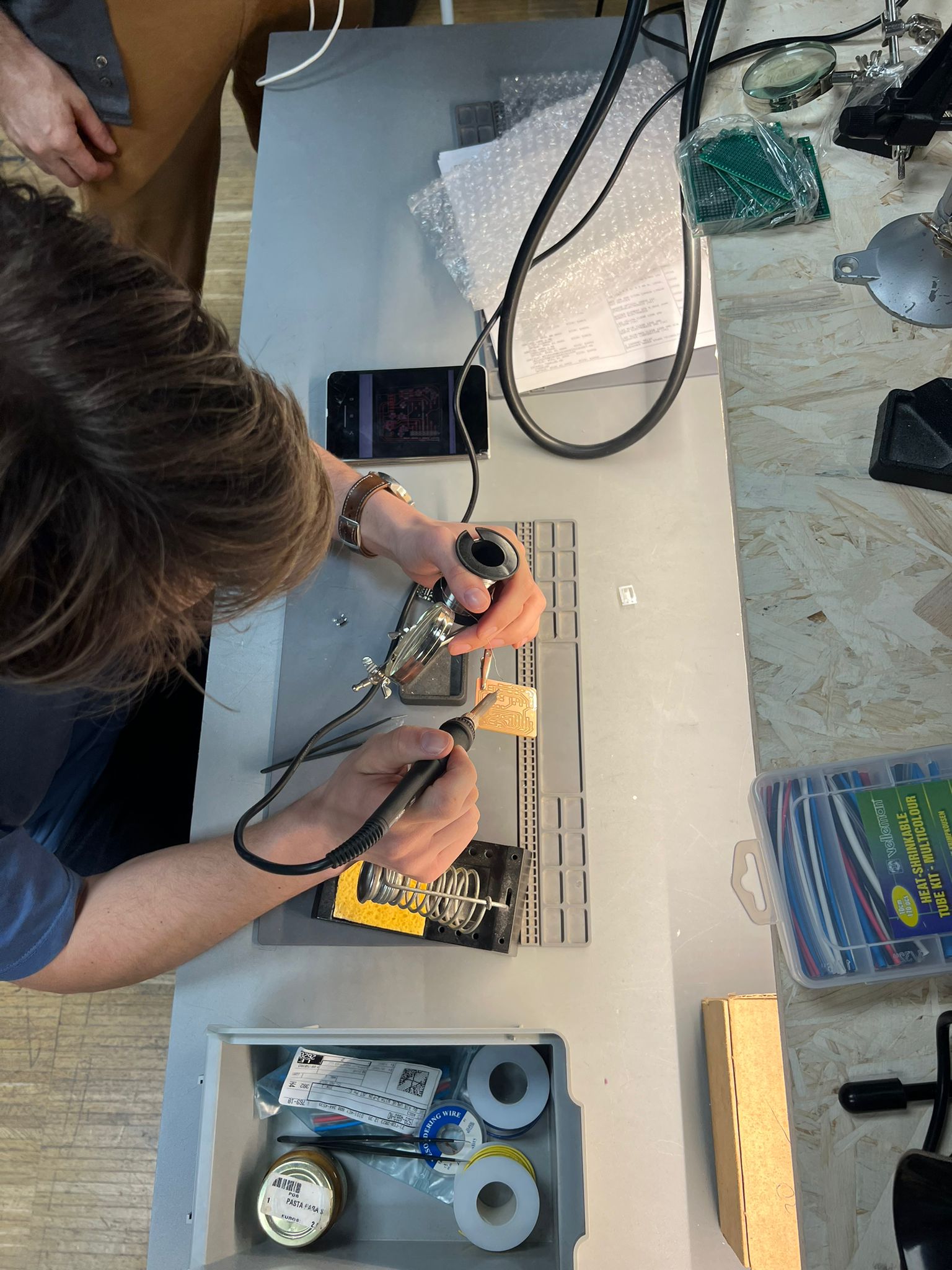
After milling, I went to select my components and started soldering them onto the board.
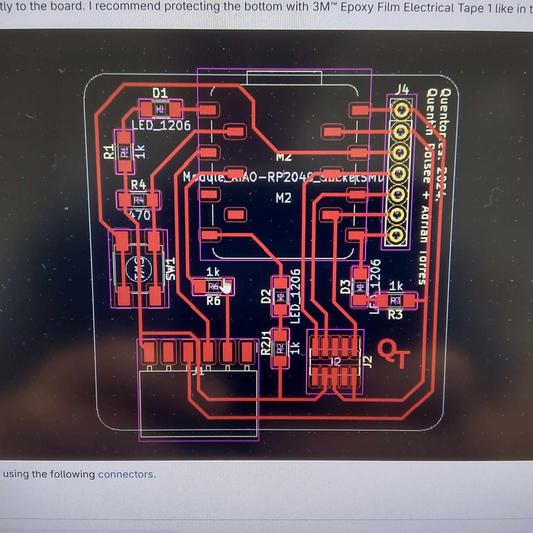
To do this, I followed the diagram provided on the Fab Academy assessment documentation.
I had no trouble soldering as I was quite used to it.
Here is the list of electronic components needed:
1 Seeed Studio Xiao RP2040
1 1.27mm header 10POS
1 2.54mm header 6POS
1 Tactile switch SMT
3 1206 blue LEDs
4 1K ohm 1206 resistors
1 499 ohm 1206 resistor
2 headers 7POS 0.1 TIN SMD (to attach Xiao to board without soldering it)
Troubleshooting
I had no issues this time and everything went smoothly with the electronics making and soldering process.
Testing the PCB
Once I finished soldering all the components, I coded a quick Blink example in the Arduino IDE:
The .ino file is available here:
const int buttonPin = D1;
const int ledPin = D0;
int buttonState = 0;
void setup() {
pinMode(ledPin, OUTPUT);
pinMode(buttonPin, INPUT_PULLDOWN);
}
void loop() {
buttonState = digitalRead(buttonPin);
if (buttonState == HIGH){
digitalWrite(ledPin, HIGH);
}
else{
digitalWrite(ledPin, LOW);
}
}
I was stuck for some time as I had simply forgotten the == and instead had written =...
After some debugging and the help of a friendly instructor, the issue was found and corrected!
The Blink worked! And so I was done for this week!

 In Mods, I had to set the following settings :
For traces and footprints: image at 1000dpi, 1/64 endmill selection, 3mm/s speed, at least 4 offsets (or set 0 to completely mill away the copper outside the traces and footprints), jog height at least 5mm for safety, origin set to 0 for all as the origin is set in the Roland machine software.
Aftewards, I checked the on/off switch to get the file out of the mods website, pressed calculate and voila !
I was then able to get a file to feed into the SRM-20 for PCB milling.
Before milling, it is necessary to prepare the machine, first loading a PCB blank with double sided tape, making sure it is as flat as possible.
Next, I attached the 1/64" endmill (being very careful not to drop it or touch the cutting part), calibrated the X/Y axis and the Z axis, and launched the milling!
Once the Traces was finished, I switched out the endmill for a 1/32", and made the holes and outline cut with that.
And that was the PCB done!
In Mods, I had to set the following settings :
For traces and footprints: image at 1000dpi, 1/64 endmill selection, 3mm/s speed, at least 4 offsets (or set 0 to completely mill away the copper outside the traces and footprints), jog height at least 5mm for safety, origin set to 0 for all as the origin is set in the Roland machine software.
Aftewards, I checked the on/off switch to get the file out of the mods website, pressed calculate and voila !
I was then able to get a file to feed into the SRM-20 for PCB milling.
Before milling, it is necessary to prepare the machine, first loading a PCB blank with double sided tape, making sure it is as flat as possible.
Next, I attached the 1/64" endmill (being very careful not to drop it or touch the cutting part), calibrated the X/Y axis and the Z axis, and launched the milling!
Once the Traces was finished, I switched out the endmill for a 1/32", and made the holes and outline cut with that.
And that was the PCB done!
 After milling the PCB, I realised the endmill had not gone deep enough in the top left corner.
 To remedy the problem, I scratched away the copper with a small knife to make sure my traces were not connected.
I tested continuity with a multimeter and it all worked!
To remedy the problem, I scratched away the copper with a small knife to make sure my traces were not connected.
I tested continuity with a multimeter and it all worked!
 To do this, I followed the diagram provided on the Fab Academy assessment documentation.
 I had no trouble soldering as I was quite used to it.
 Here is the list of electronic components needed:
1 Seeed Studio Xiao RP2040
1 1.27mm header 10POS
1 2.54mm header 6POS
1 Tactile switch SMT
3 1206 blue LEDs
4 1K ohm 1206 resistors
1 499 ohm 1206 resistor
2 headers 7POS 0.1 TIN SMD (to attach Xiao to board without soldering it)
Here is the list of electronic components needed:
1 Seeed Studio Xiao RP2040
1 1.27mm header 10POS
1 2.54mm header 6POS
1 Tactile switch SMT
3 1206 blue LEDs
4 1K ohm 1206 resistors
1 499 ohm 1206 resistor
2 headers 7POS 0.1 TIN SMD (to attach Xiao to board without soldering it)