2. Computer Aided Design
This second week I worked on different CAD (computer aided design) tools and made a render of my final project idea from last week, the Simple Phone.
Having worked briefly with Blender before for a simple 3D-printable object edit that did not go very well, I was a bit aprehensive going into this week.
It ended up going very well, as you'll find out...
Introduction
CAD has been around since the 1960s, but it is not until the early 2000s that open-source and accessible CAD software started being the norm.
We first learned about different 2D software, such as as the open-source GIMP, KRITA, and browser-based PIXLR, as well as Inkscape (a computer-aided drafting software).
While learning the basis of Inkscape, we discussed the basic principles of these softwares, pixels and vectors. Where pixels draw every individual dot at a certain resolution in order to make an image, vectors are the literal geographic representations of that image, meaning that as you zoom in there is no blur.
While vectors are great, they also require more processing power from your computer, as they require constant rendering.
Here are some images which show the difference between the two, the top drawing is vectorised, and the bottom drawing is an image.
The first image shows them zoomed out, where they look identical. If you zoom in as in the 2nd image, you can see the difference, as the pixels are clearly visible on the bottom while the vectorised drawing is still just as smooth.


3D CAD Software
We also learned about 3D software, and the differences between Mesh and Nurbs.
We made the same Lego brick with Tinkercad, Rhino, Blender and Fusion so we could quickly discover the different softwares and what they could do.
Here are a few of the Lego bricks I made, you can see the various state of completeness...
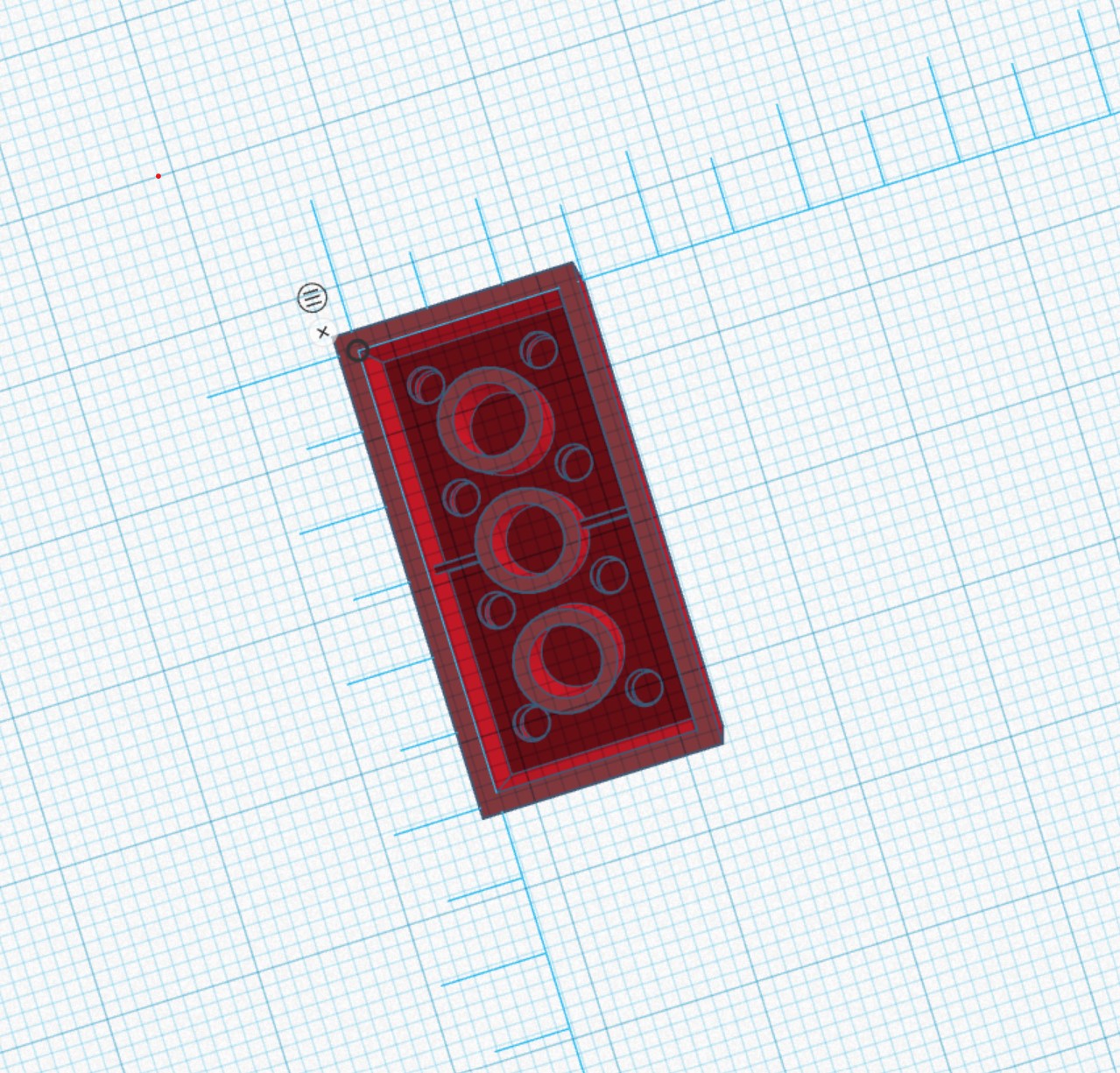
First the Tinkercad brick:
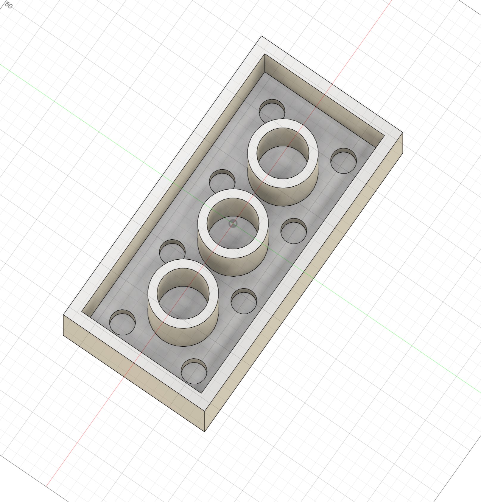
 Next the Fusion brick:
 Then the Rhino brick:
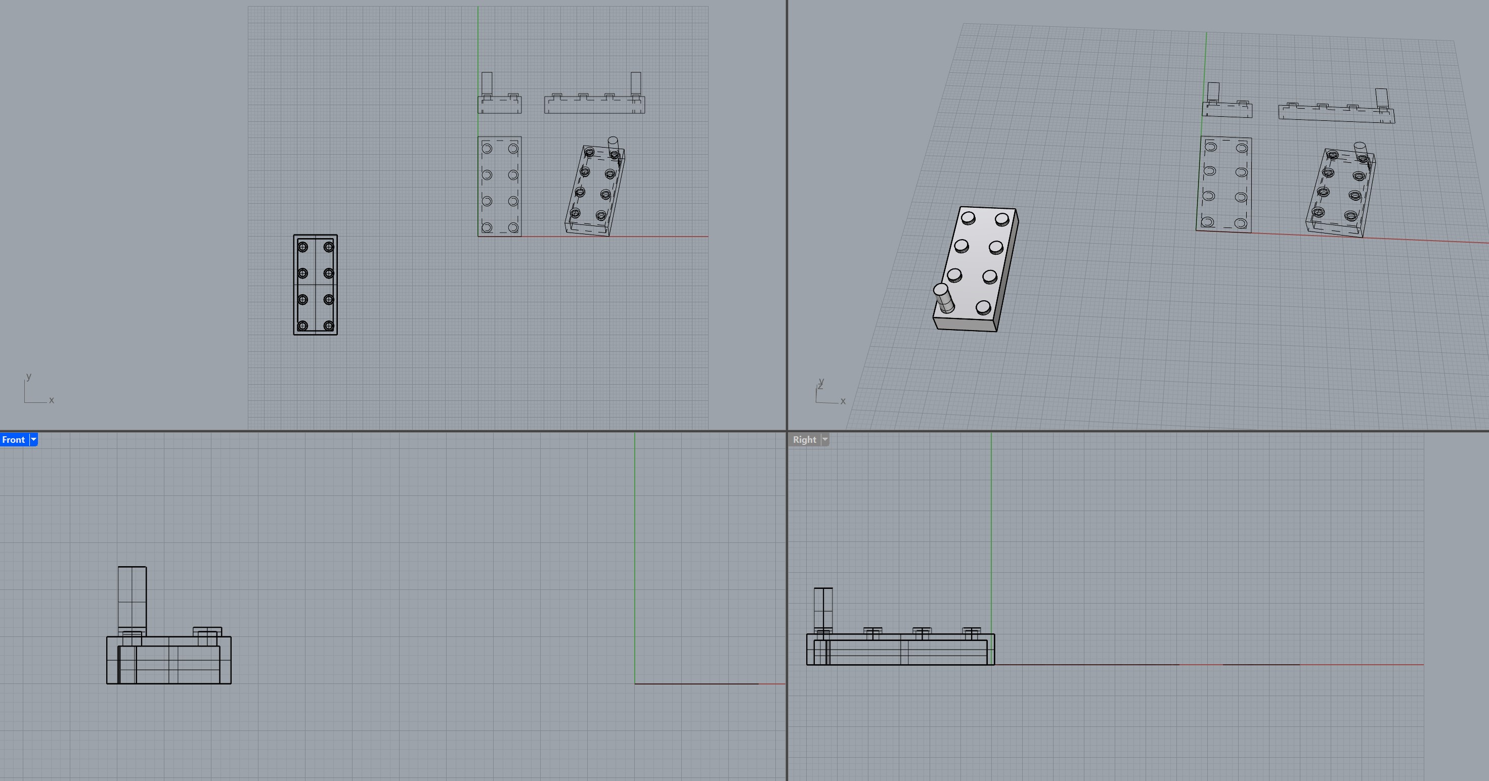 I did not finish this brick but I ended up having some fun with Rhino and showing the brick in 2D with the Make2D command.
And finally the Blender brick in all its glory:
I did not finish this brick but I ended up having some fun with Rhino and showing the brick in 2D with the Make2D command.
And finally the Blender brick in all its glory:
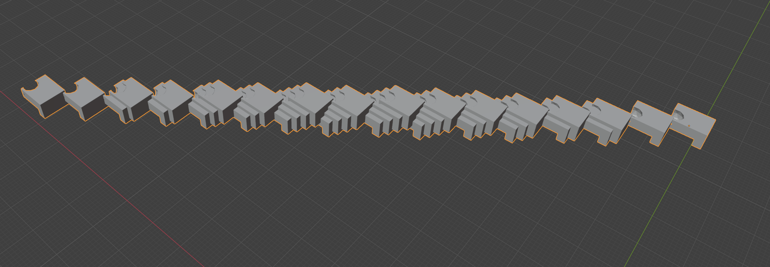 As you can see, this ended up being a mess, as Blender was not recognising my keyboard properly and I could not follow any of the shortcuts from our instructor...
I ended up doing some more freeform things, playing aroun with cutting tools and array multipliers.
I immediately felt Rhino was closer to my method of working than the others, as having the option to type in the command of what you want to do seems very intuitive.
I also really enjoyed the default 4-panel view and the built-in documentation.
While starting to model my final project (as you'll see below), I felt I needed more background on Rhino so I decided to follow a few tutorials.
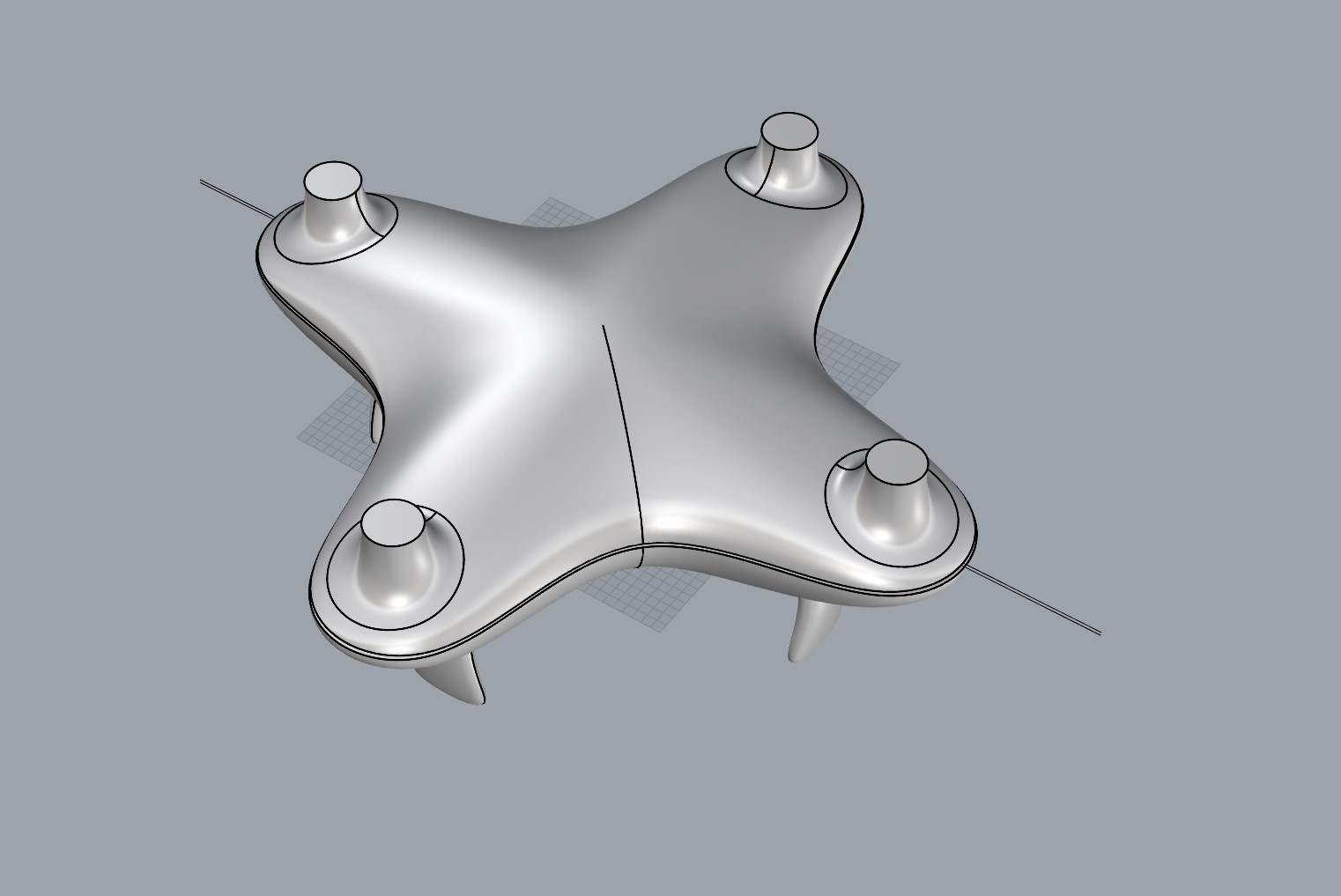
I started with this drone-making tutorial by RHINO TUTORIALS on YouTube.
This taught me about symmetric modelling and using the Gumball along with control points for precise curvature adjustments.
Here is the (nearly) finalised drone I made with this tutorial, just missing the flying blades.
As you can see, this ended up being a mess, as Blender was not recognising my keyboard properly and I could not follow any of the shortcuts from our instructor...
I ended up doing some more freeform things, playing aroun with cutting tools and array multipliers.
I immediately felt Rhino was closer to my method of working than the others, as having the option to type in the command of what you want to do seems very intuitive.
I also really enjoyed the default 4-panel view and the built-in documentation.
While starting to model my final project (as you'll see below), I felt I needed more background on Rhino so I decided to follow a few tutorials.
I started with this drone-making tutorial by RHINO TUTORIALS on YouTube.
This taught me about symmetric modelling and using the Gumball along with control points for precise curvature adjustments.
Here is the (nearly) finalised drone I made with this tutorial, just missing the flying blades.
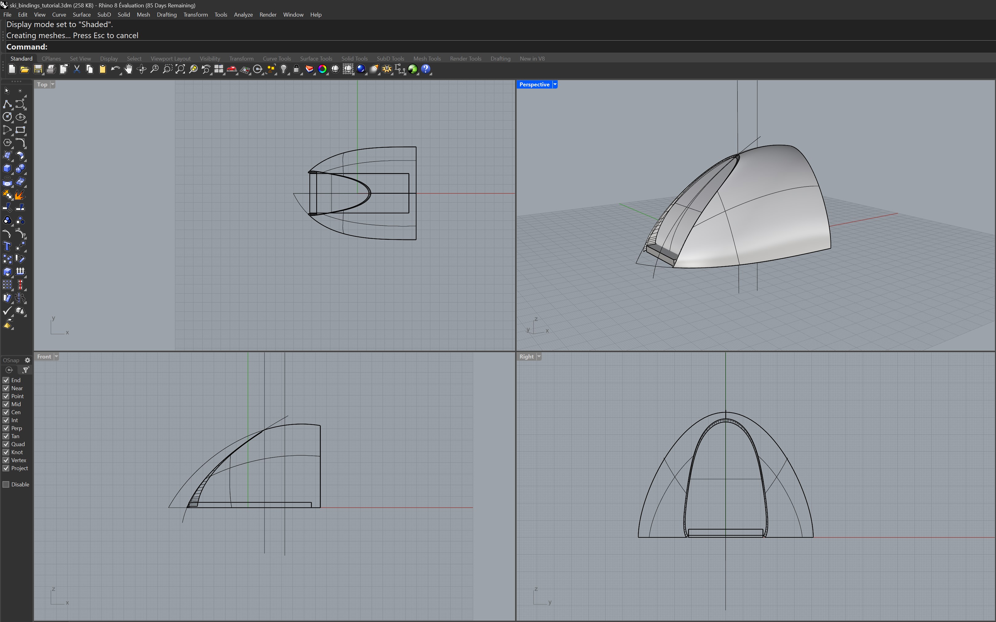
 I then watched this ski-binding tutorial by Rhinoceros3d also on YouTube.
While I did not finish it, this one helped me think of complex objects as a combination of simple shapes, in order to keep my workflow as fluid as possible, as well as how to use the Rhino history tool.
Here is an image of the design process of the ski binding.
I then watched this ski-binding tutorial by Rhinoceros3d also on YouTube.
While I did not finish it, this one helped me think of complex objects as a combination of simple shapes, in order to keep my workflow as fluid as possible, as well as how to use the Rhino history tool.
Here is an image of the design process of the ski binding.
3D Modelling my Final Project
You can find the 3D model here.
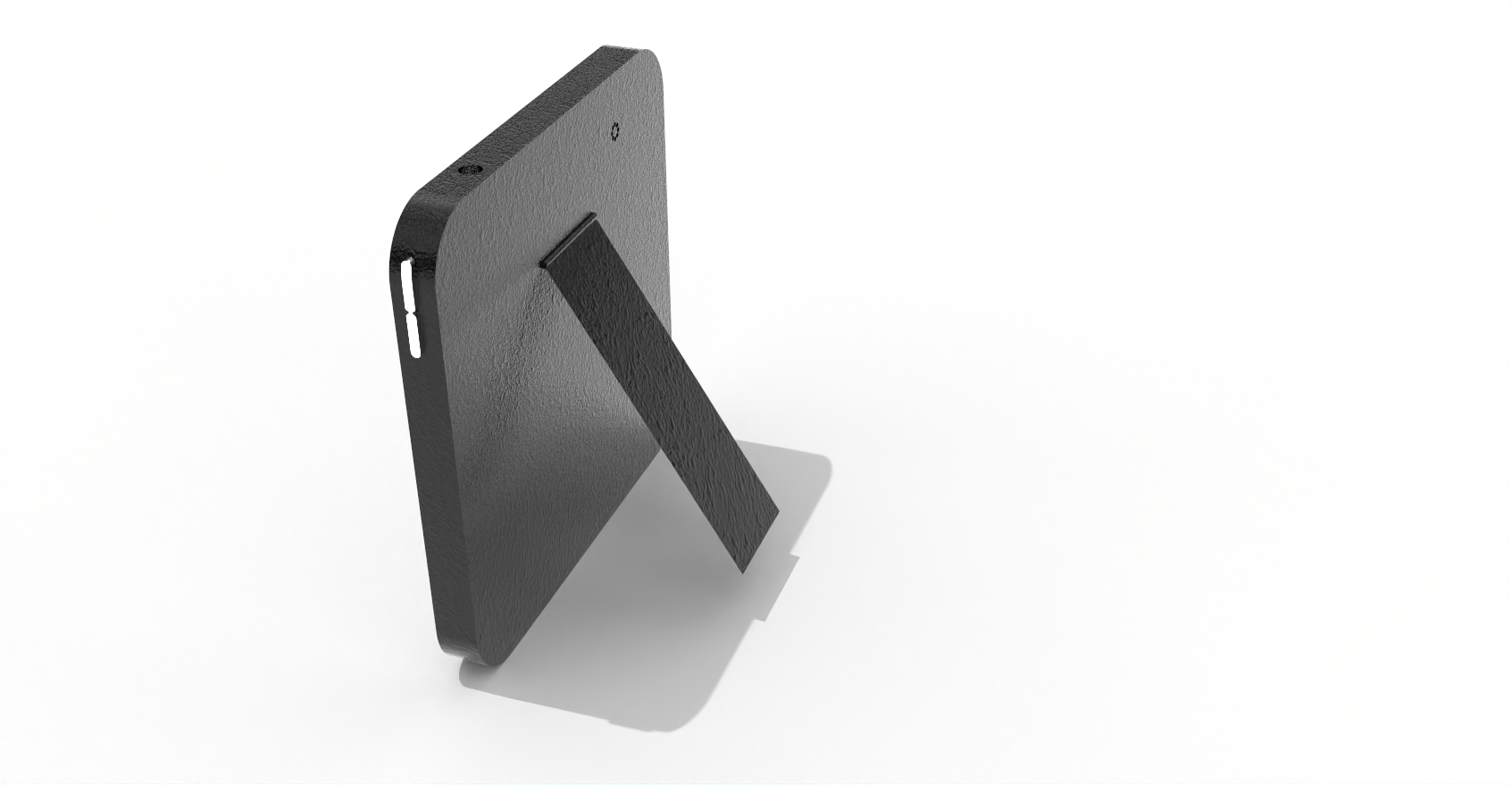
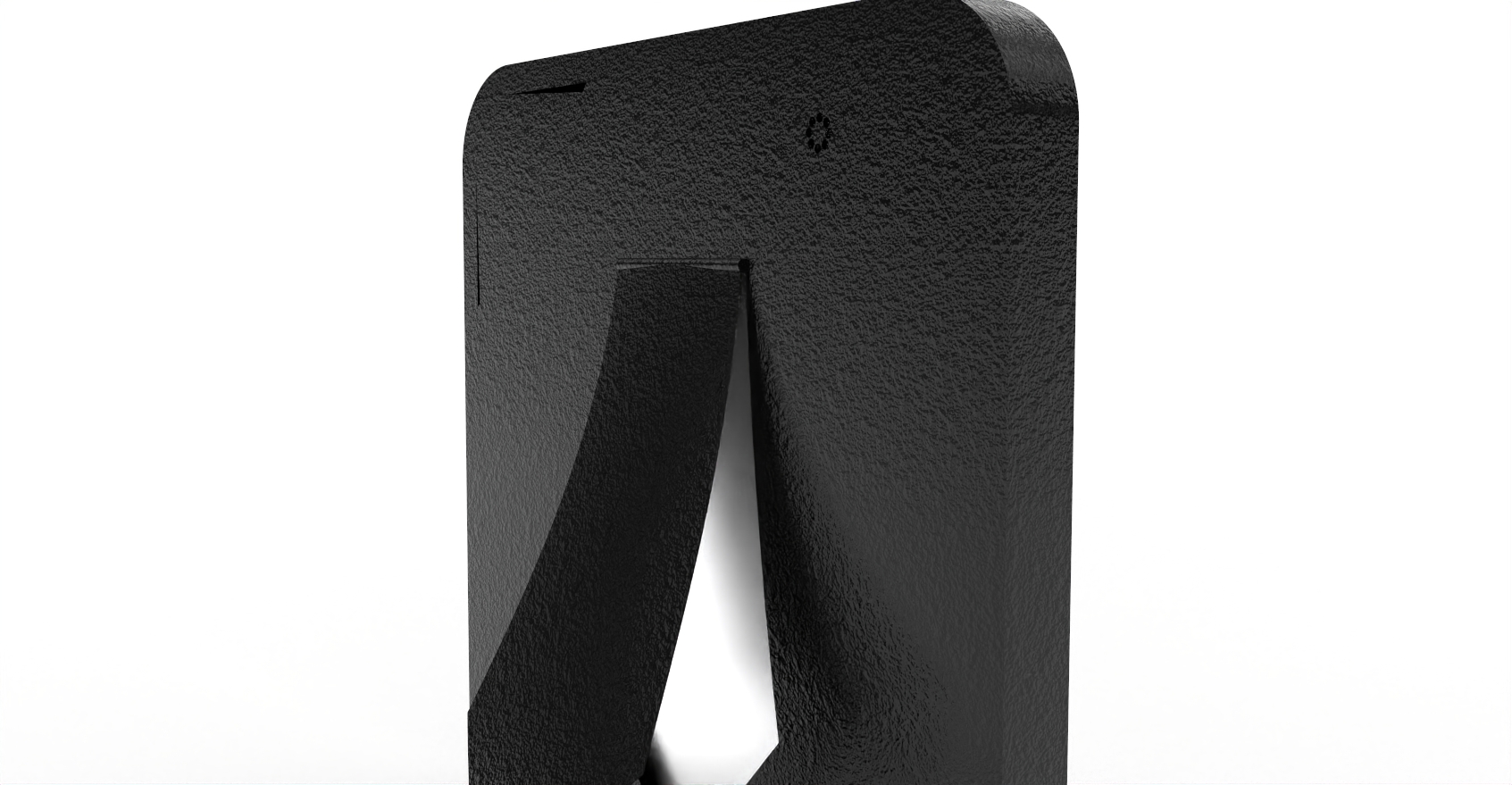
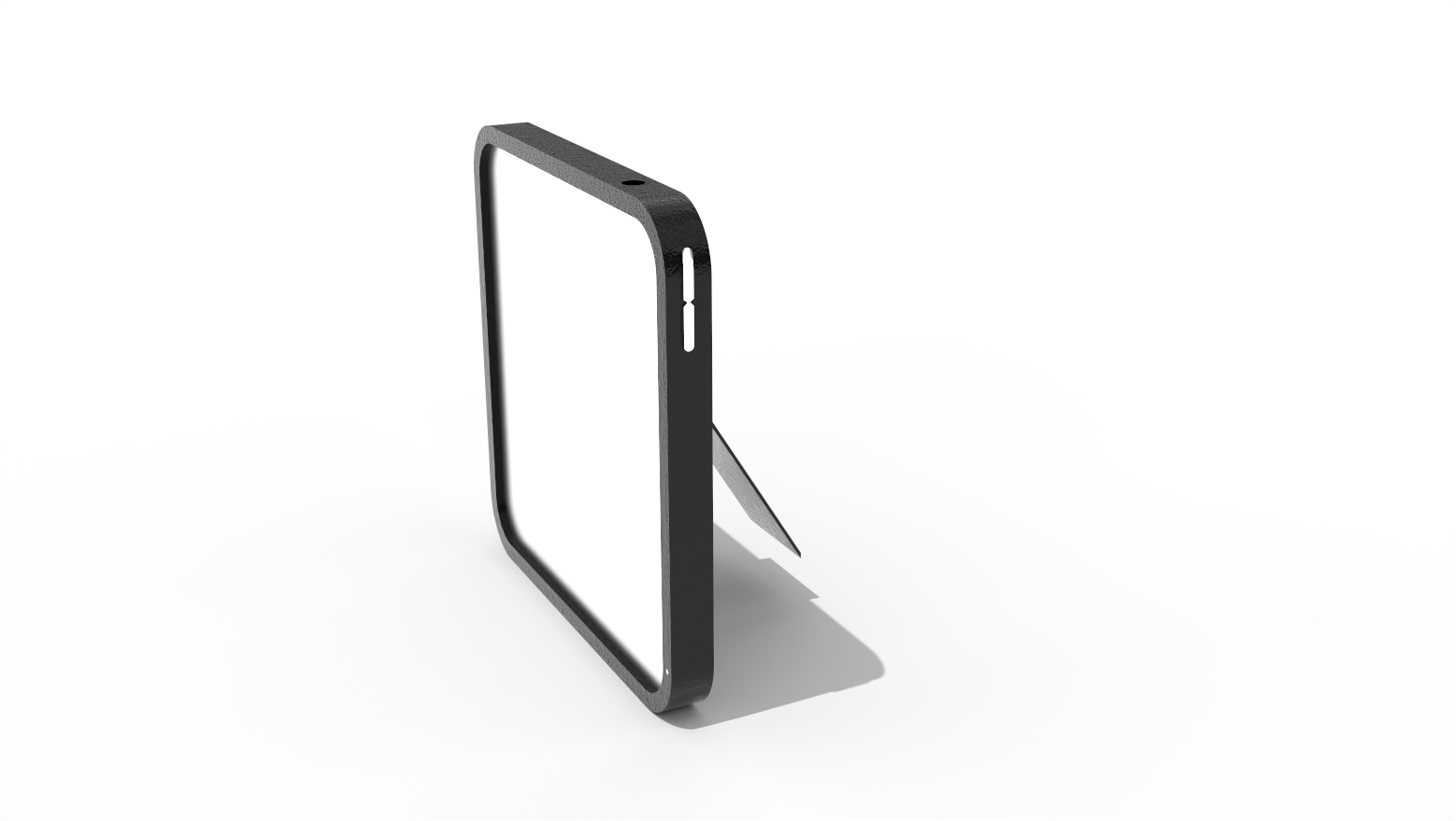
Here is what it looks like from a back angle showing the kickstand and some of the features.
 To be clear, this is a slightly different project than from week 1. The basic form factor is similar, but the project itself has been changed into a simple musical accompaniment device.
I wanted to keep the square form factor and the e-ink touch screen, but also wanted to apply the project more towards my passion and field of expertise, music.
The Simple Phone became the "Simple Music Companion" (name to be confirmed at a later date...), a standalone basic accompaniment tool for musicians, which uses a microphone with pitch detection to pick up the basic chord structure of someone's playing, and accompanies the musician with some simple piano, with different stylistic and rhythmic options to be selected on the screen. It then is able to save the MIDI track of what it has performed and that can be used as the basis of a track in a DAW software later.
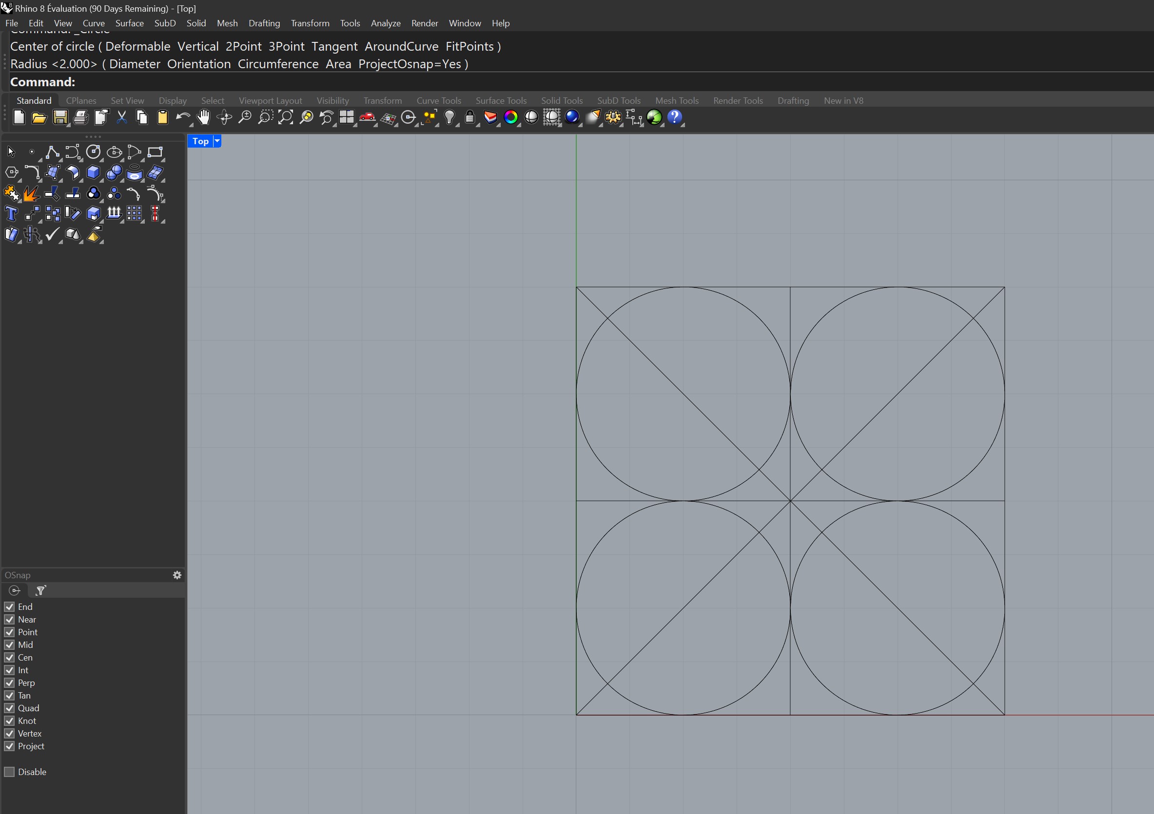
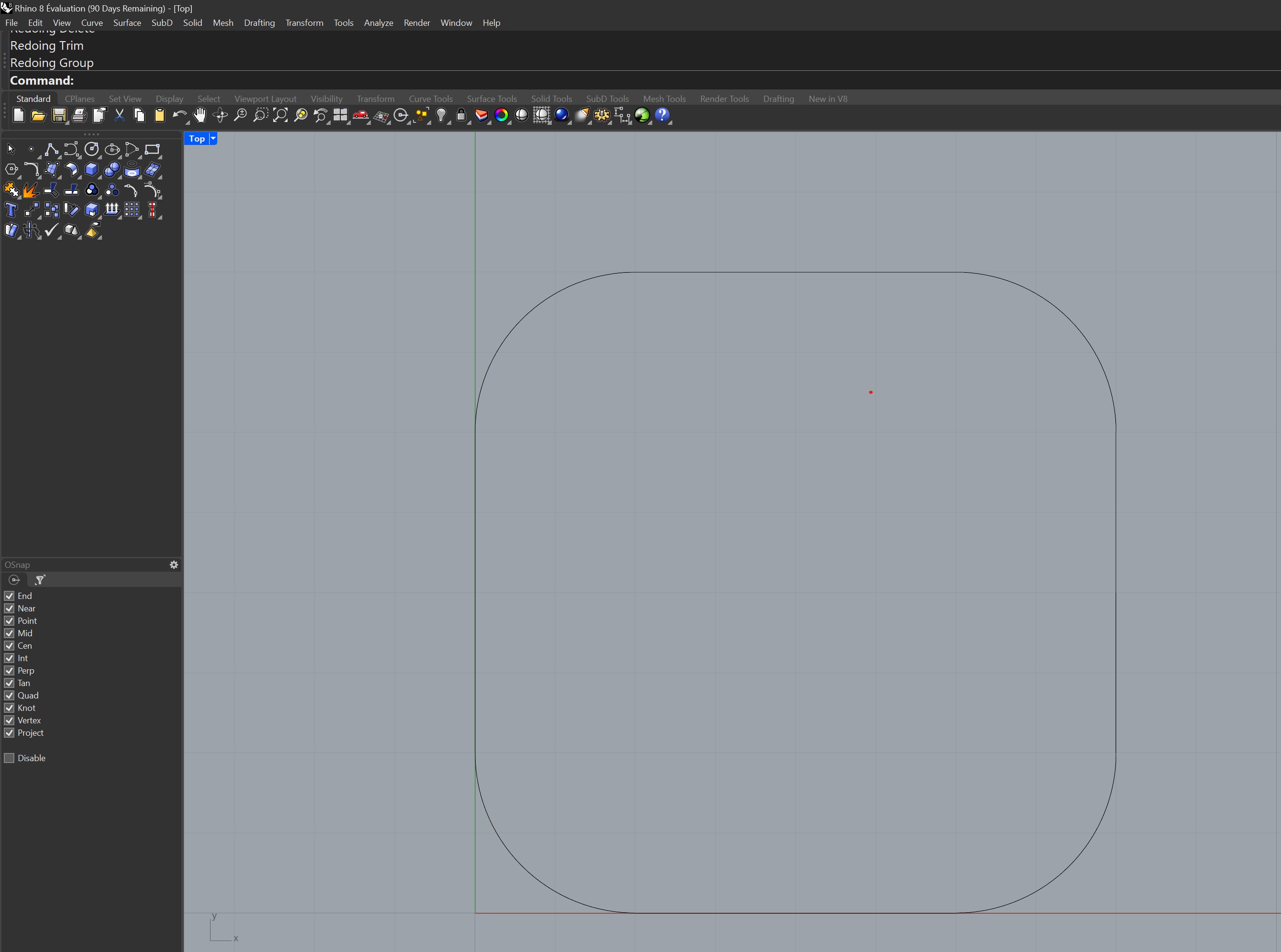
I started by designing the 2D cube, wanting to keep my design simple, and immediately ran into the very simple issue of not knowing how to round cube edges automatically...
I made a relatively complex design, as shown below, using circles to round out the corners, not great...
To be clear, this is a slightly different project than from week 1. The basic form factor is similar, but the project itself has been changed into a simple musical accompaniment device.
I wanted to keep the square form factor and the e-ink touch screen, but also wanted to apply the project more towards my passion and field of expertise, music.
The Simple Phone became the "Simple Music Companion" (name to be confirmed at a later date...), a standalone basic accompaniment tool for musicians, which uses a microphone with pitch detection to pick up the basic chord structure of someone's playing, and accompanies the musician with some simple piano, with different stylistic and rhythmic options to be selected on the screen. It then is able to save the MIDI track of what it has performed and that can be used as the basis of a track in a DAW software later.
I started by designing the 2D cube, wanting to keep my design simple, and immediately ran into the very simple issue of not knowing how to round cube edges automatically...
I made a relatively complex design, as shown below, using circles to round out the corners, not great...
 I then trimmed the points of the rectangle using the circles, leaving me with the following rounded square.
 After playing around with Rhino for a bit of time, I figured out I could build a rectangle with the Rounded attribute and select how rounded I wanted my corners! Much better.
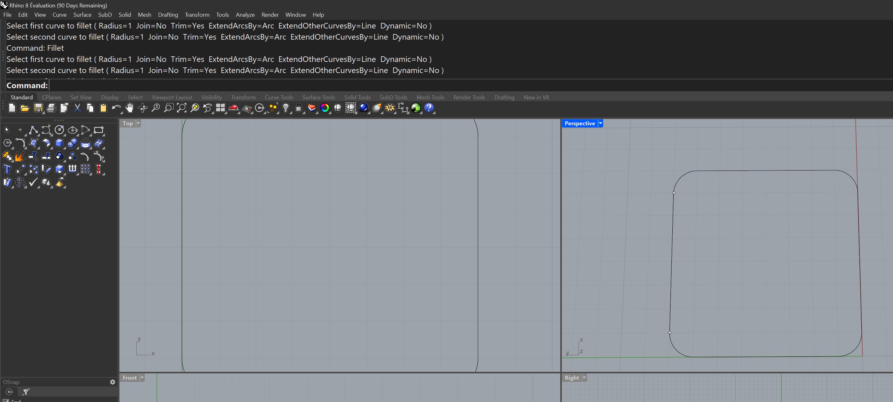 I then offset the resulting square to get the inner dimensions of the screen, and extruded both to get two objects, the screen and the outer shell of the project.
Backplate Render Issues
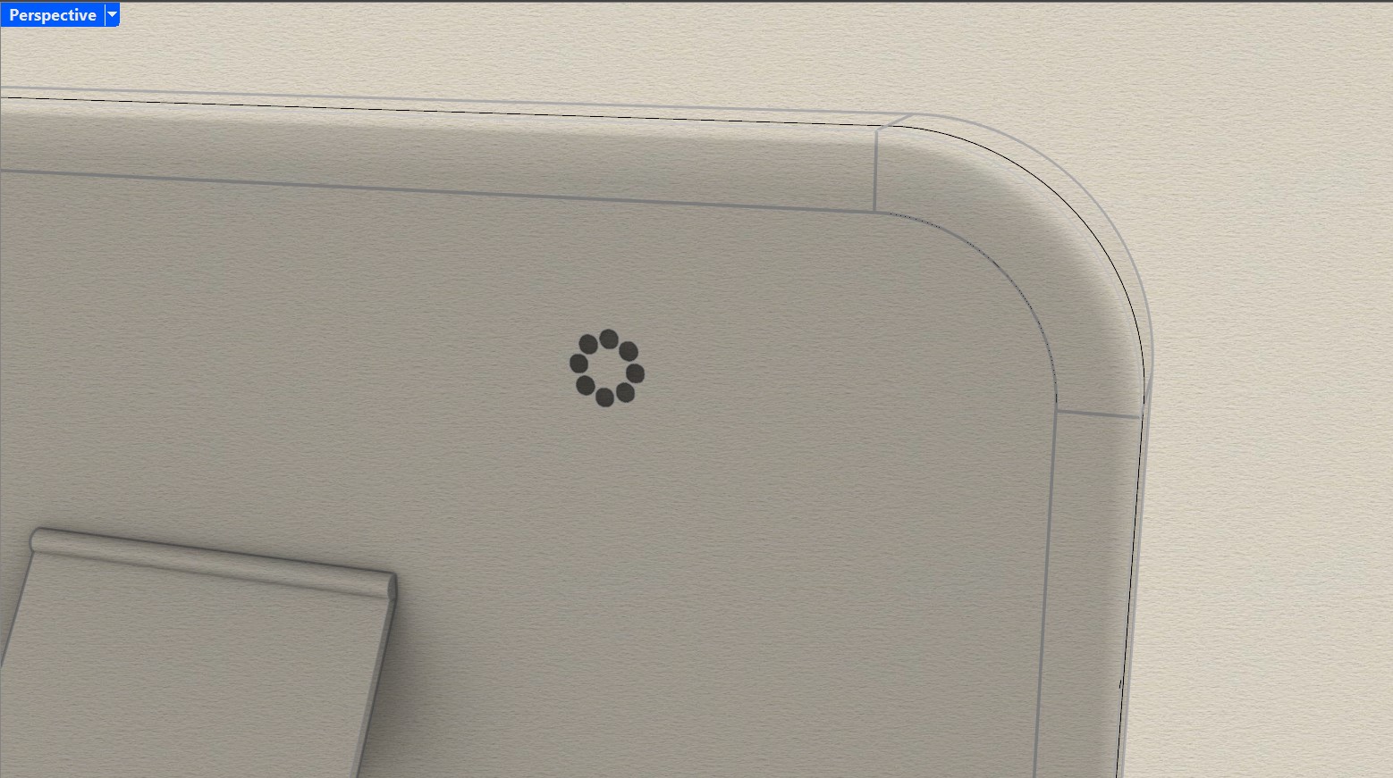
I made the outer shell protrude away from the screen in both directions, and then closed the back of it with another object, the backplate.
It took me some time to get the backplate perfect, with a lot of different curves and modifications, so by the time I was happy it looked like the image below.
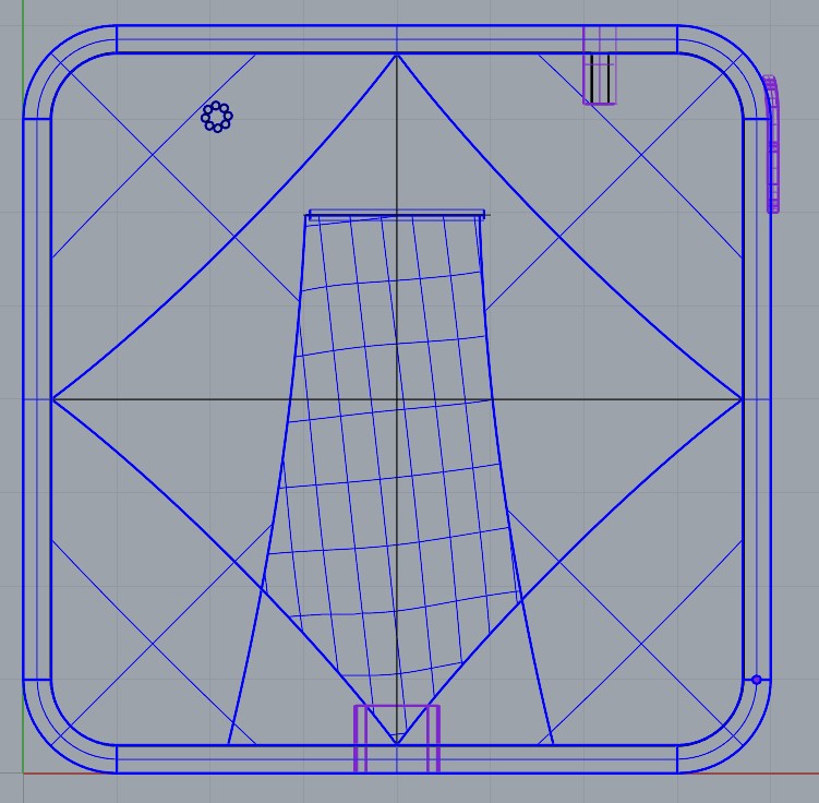 Because of all the different intersecting curves, this was causing a rendering issue where some shadows appeared seemingly out of nowhere on the backplate.
Looking at the Rhino documentation, I was able to fix the issue with the "MergeAllCoplanarFaces" command, which then resulted in a much less crowded backplate.
Because of all the different intersecting curves, this was causing a rendering issue where some shadows appeared seemingly out of nowhere on the backplate.
Looking at the Rhino documentation, I was able to fix the issue with the "MergeAllCoplanarFaces" command, which then resulted in a much less crowded backplate.
Kickstand
As you can see in the image above, I had been trying to work on a shape for a kickstand, and I wanted it to have a graceful curve.
Using some ideas from the videos referenced above, I tried to edit the surface control points to make a curved kickstand, resulting in the following:
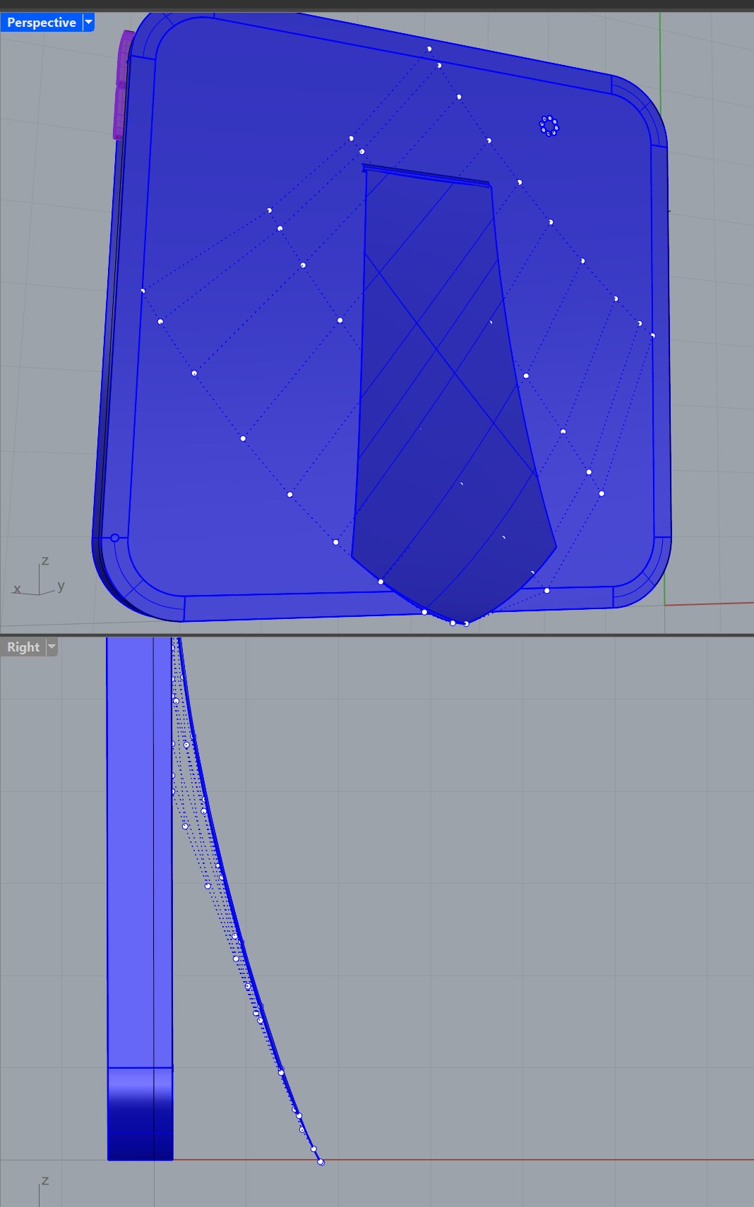
 Putting some time into it made me think a curved kickstand was neither natural nor a good idea, so I simply made a straight kickstand, with a little cylinder attached to make it look rotative, as below.
Adding the Ports, Speaker, Microphone, and Volume Button
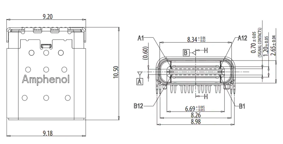
I decided that for a realistic looking model, I needed to add a few ports (USB type C and 3.5mm audio output), a speaker and microphone, and a volume rocker button.
I found the USB type C dimensions from Mouser Electronics and replicated that into my project.
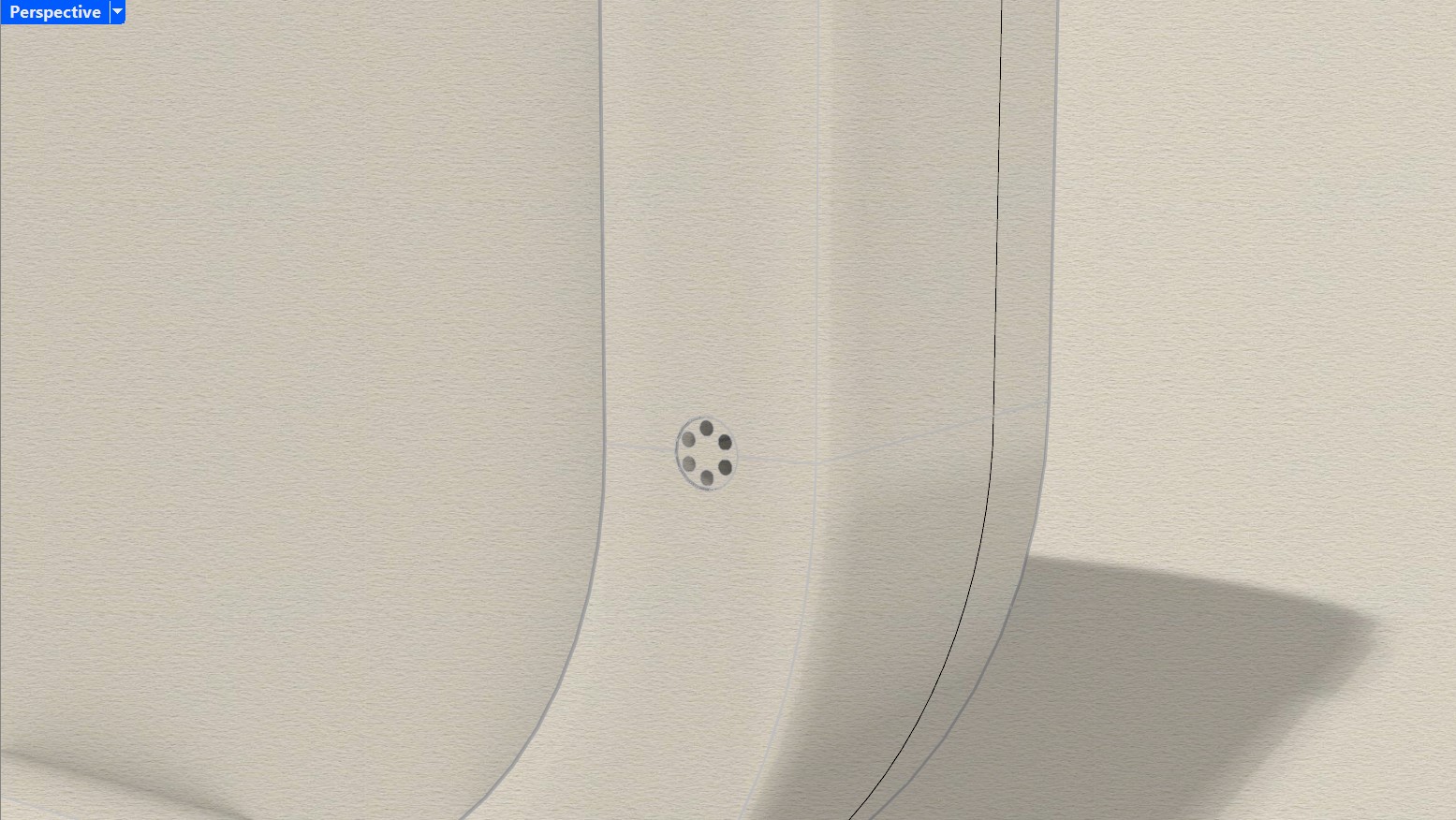
 The speakers and microphone were simple radial arays that I cut away from the main shape, leaving a hole for the speaker and making the microphone a different material (metal).
Here are some artistic renditions of the two.
The speakers and microphone were simple radial arays that I cut away from the main shape, leaving a hole for the speaker and making the microphone a different material (metal).
Here are some artistic renditions of the two.
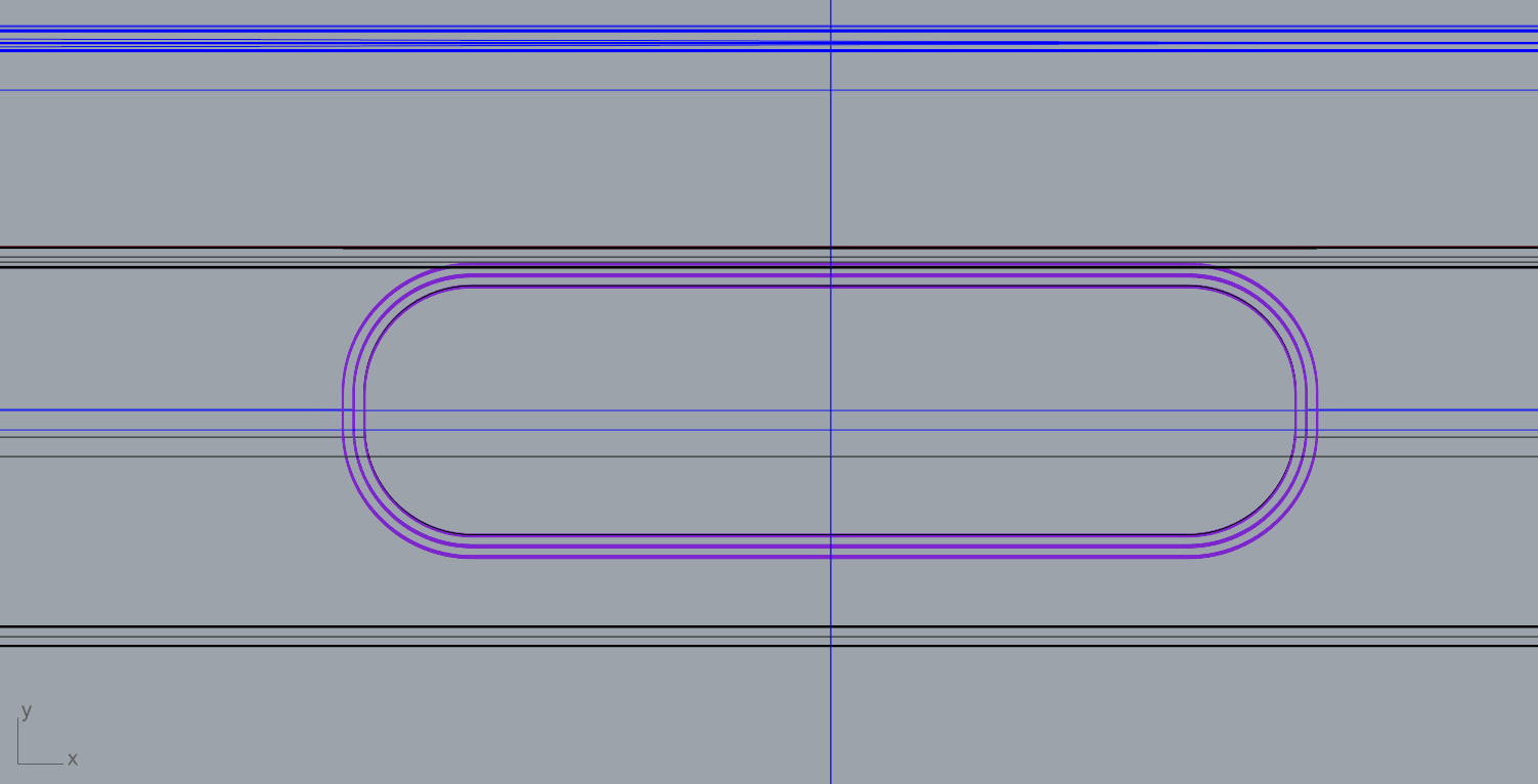
 As for the volume rocker, I wanted it to curve along with the device's curve, so I created the basic shape and then projected it onto the outer shell of my device, before extruding the shape.
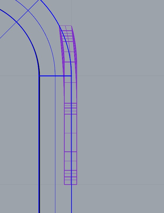 Here is the render of the end result:
Making a (very) basic 2D logo
You can find the 2D file here
For the 2D portion of this week, I decided to use InkScape to design a simple logo.
I did not spend a lot of time on this part, preferring to focus on the 3D modelling aspect.
I turned to ChatGPT for a catchy name for my final project idea, and ended up getting "TuneGenie", which will be OK enough for this week.
I then followed some of the steps in this Instructables tutorial to learn how to design a logo in Inkscape.
I started by drawing a basic idea in freehand, of a musical note sideways to look like a genie lamp, with some smaller notes coming out.
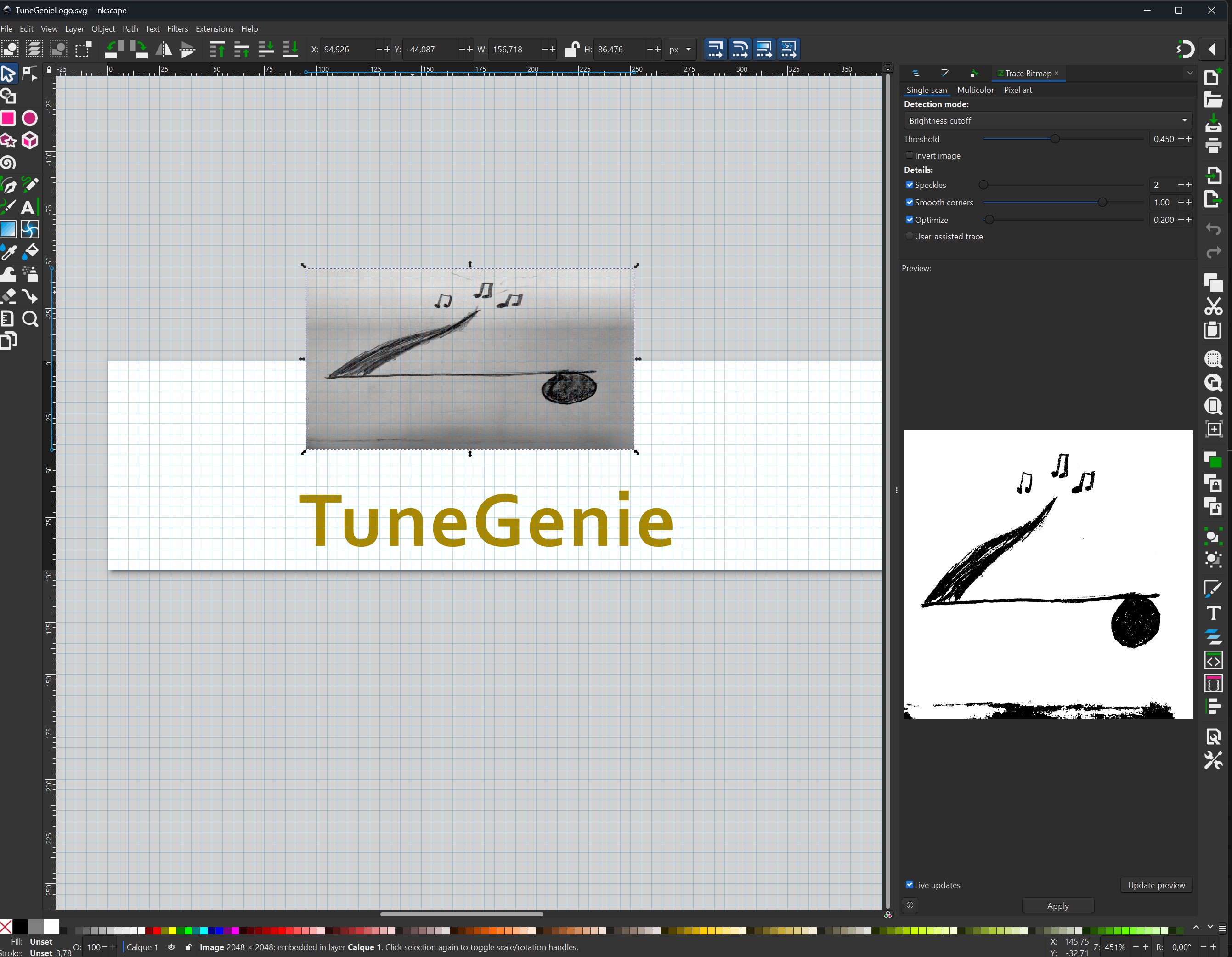
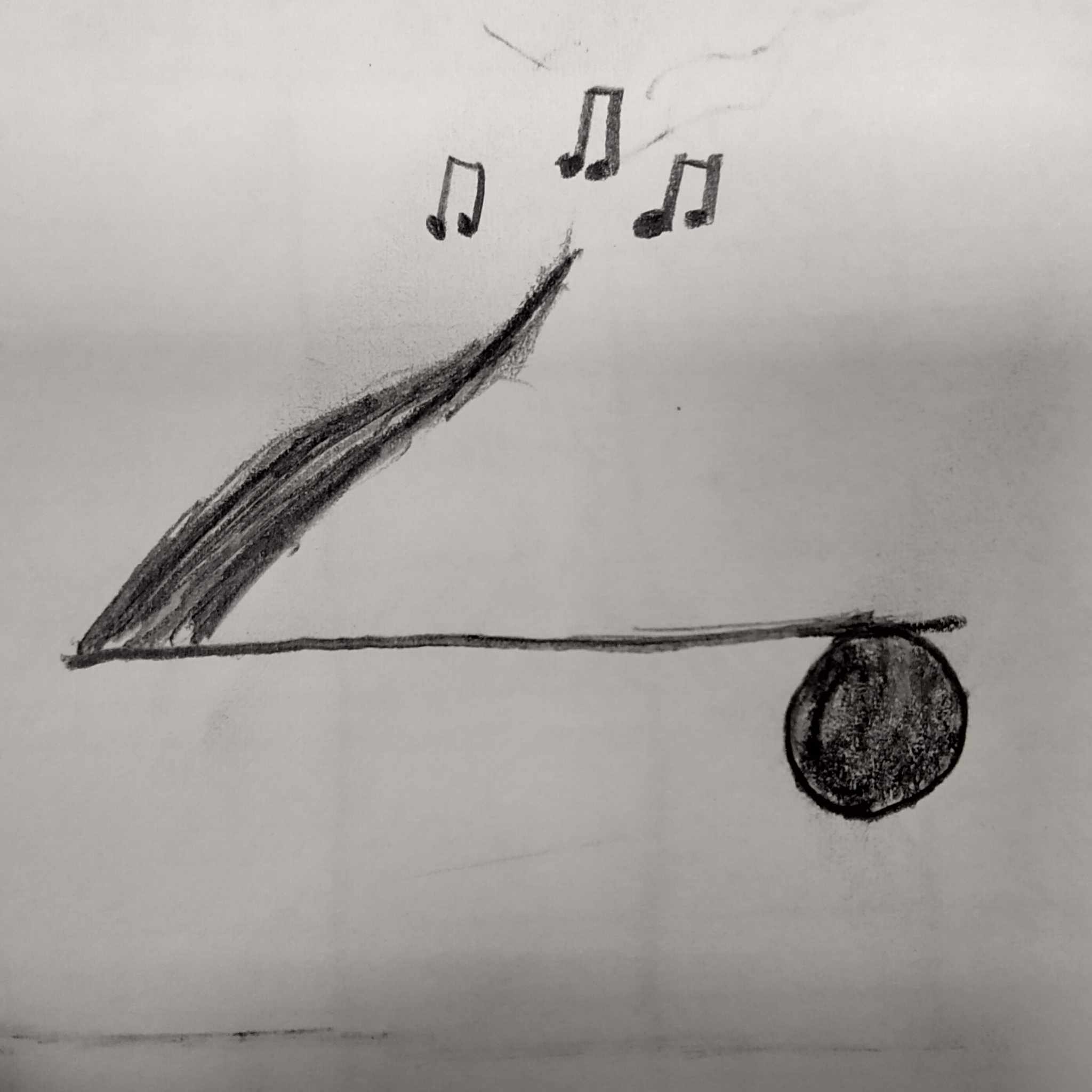 I then took a photo of that, imported it into Inkscape and converted used the "trace bitmap" option to import it and have more control over the drawing.
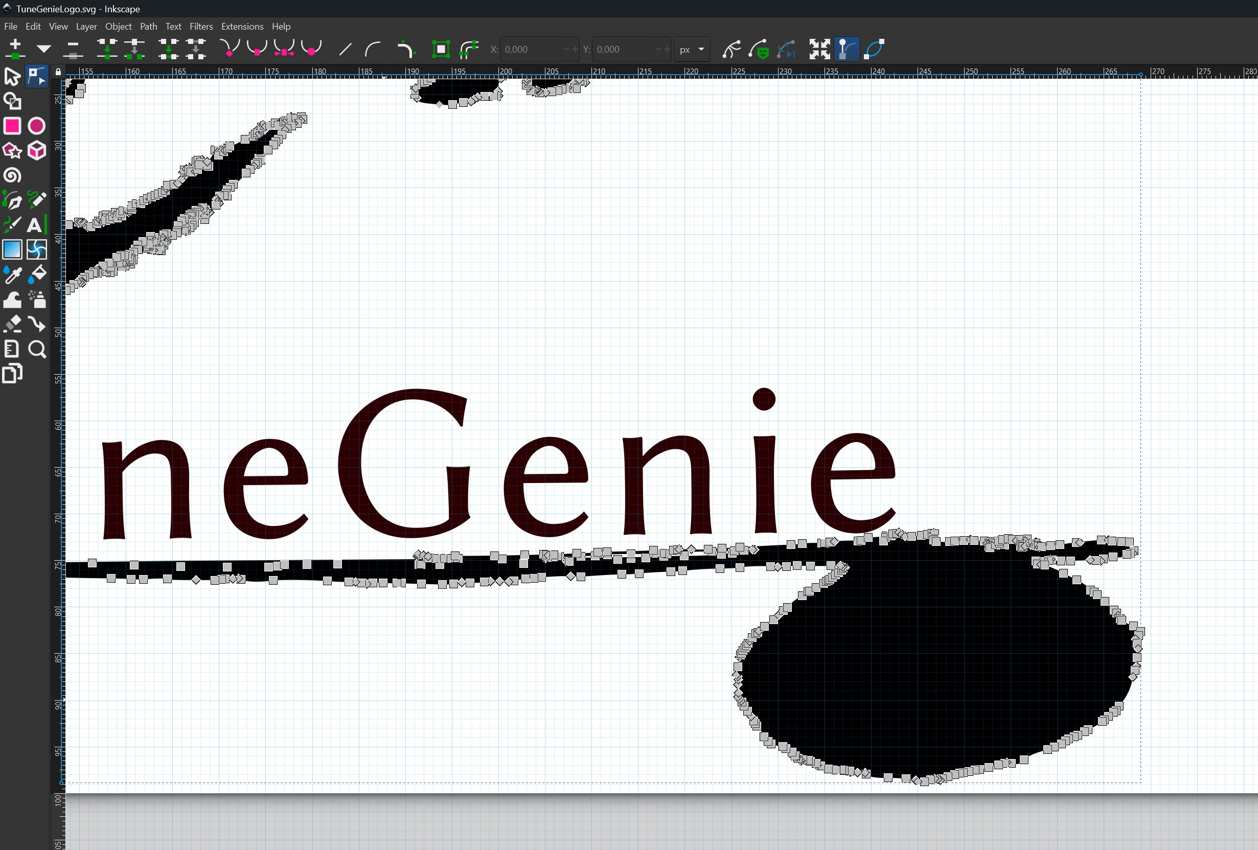 I then created a path for the text to follow along the slight curvature of the note, messed around with text sizing, colouring and position, and voilà ! My simple work in progress logo:
 I also tried out another 2D software, which I used for 3D design already, Rhino ! Rhino is a great 2D software, especially if you are already comfortable with the 3D aspect of it.
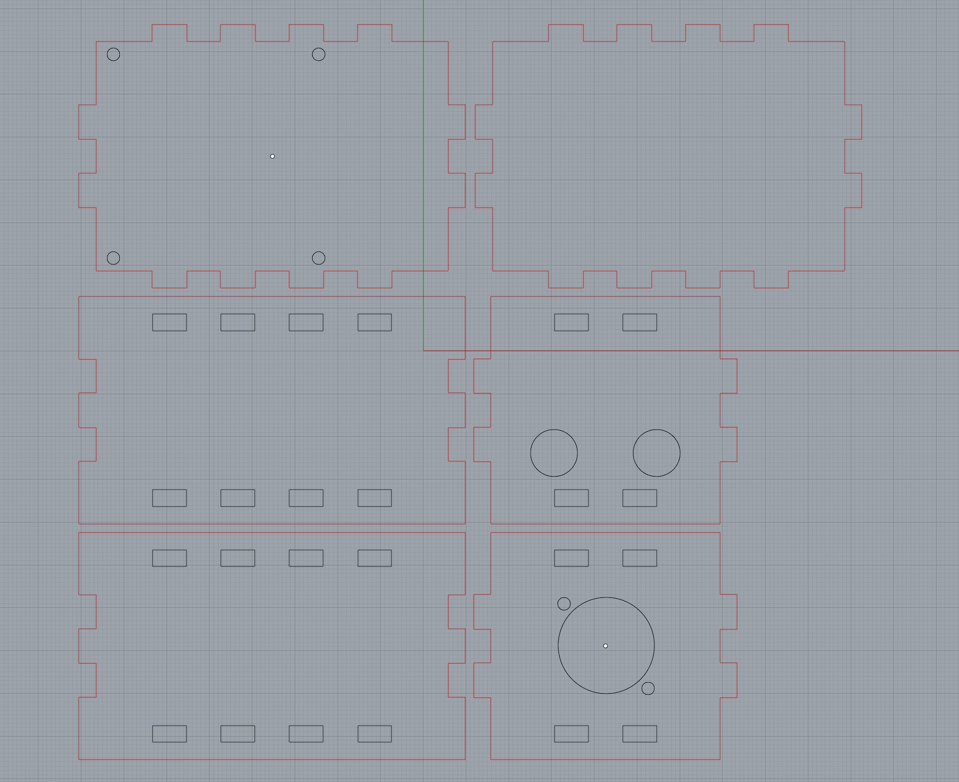
I made a simple 2D laser-cuttable box in Rhino, to house a small microphone preamplifier.
You can find the box file here
I also tried out another 2D software, which I used for 3D design already, Rhino ! Rhino is a great 2D software, especially if you are already comfortable with the 3D aspect of it.
I made a simple 2D laser-cuttable box in Rhino, to house a small microphone preamplifier.
You can find the box file here
 Overall I liked Rhino a lot more than Inkscape, even for 2D design. And since I will also be using it for 3D design, it is very convenient!
And that's it for Week 2! Next week we are getting into computer-controlled cutting...
Overall I liked Rhino a lot more than Inkscape, even for 2D design. And since I will also be using it for 3D design, it is very convenient!
And that's it for Week 2! Next week we are getting into computer-controlled cutting...