This week we worked on embedded programming with different microcontrollers.
The assignment was to write a program for a microcontroller development board that I made to interact with local input &/or output devices and communicate with wired &/or wireless devices.
For this I chose my Seeed Studio Xiao RP2040, which I made a board for back in week 4 for electronics production week.
Group Assignment
The group assignment for this week can be found here.
Understanding the Datasheet
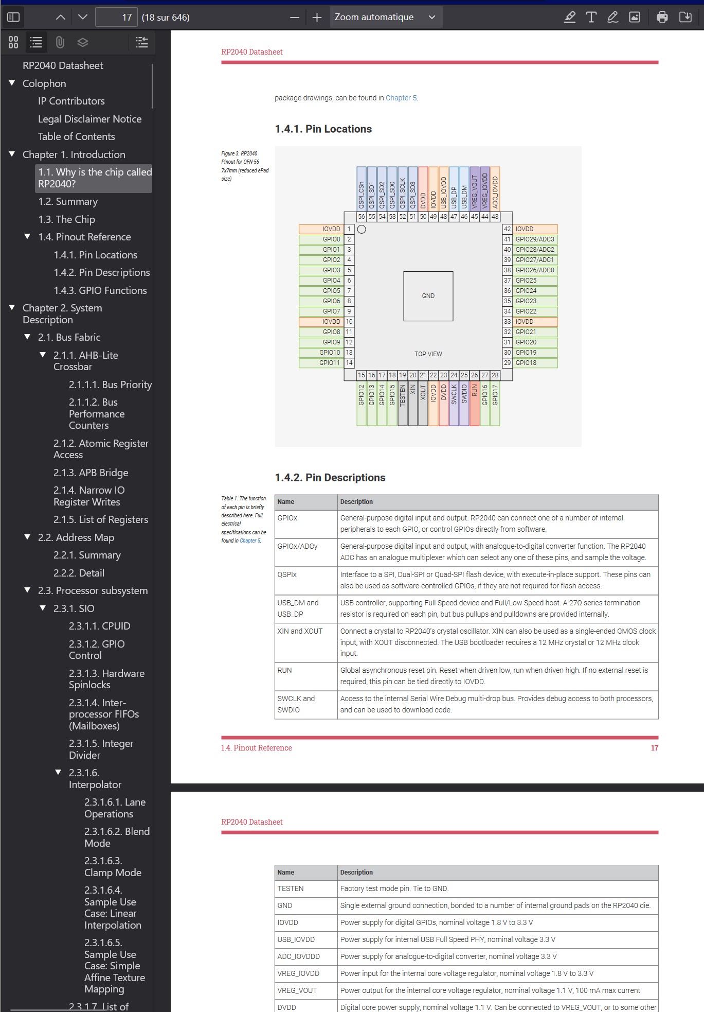
To begin the assignment, I went to look at the Seeed Studio Xiao RP2040 datasheet, which can be found here
This gave me some useful insight into the chip and how it works, for example all the pin locations of this small, high performance chip!
The datasheet provides all the resources needed to understand the RP2040 at a low level, to really get into its architecture, how it works, all the pins and what they can and can't do, and how to make it all come together.
Programming the Microcontroller
The .ino file can be found here!
For programming the microcontroller, I used the Arduino IDE, and with Tony's great help wrote a code for turning the LED on when pushing the included button, and back off when pushing the button again.
const int buttonPin = D1;
const int ledPin = D0;
const int DEBOUNCE_TIME = 100;
bool buttonPressed = 0;
int debounceCount = 0;
void setup() {
pinMode(ledPin, OUTPUT);
pinMode(buttonPin, INPUT);
}
void loop() {
bool buttonState = digitalRead(buttonPin);
bool ledState = digitalRead(ledPin);
if (buttonState && debounceCount < DEBOUNCE_TIME) debounceCount++;
if (!buttonState) debounceCount--;
if (debounceCount >= DEBOUNCE_TIME && !buttonPressed){ // button is officially pressed
digitalWrite(ledPin, abs(ledState - 1));
buttonPressed = true;
} else if (!buttonState && debounceCount < 0) { // button is officially not pressed
debounceCount = 0;
buttonPressed = false;
}
}
The first part of this code:
const int buttonPin = D1; This line will be used to tell the microcontroller that the button is on pin 1.
const int ledPin = D0; Similarly, this will be used to tell the microcontroller that the LED is on pin 0.
const int DEBOUNCE_TIME = 100; This is used to ensure the button is pressed, and not an accident. This will be used in the loops in the main code.
bool buttonPressed = 0; This boolean is either 0 or 1 (off or on, false or true) and is used to say whether the button is pressed or not
int debounceCount = 0; This variable will be used to count the connection cycles of the button press.
Then, in the setup portion, we tell the microcontroller what to do with the ledPin and buttonPin. the LED is an output since it will receive voltage in order to turn on. The button is an input since it will send a voltage to the microcontroller, letting it know to send voltage to the LED.
void setup() {
pinMode(ledPin, OUTPUT);
pinMode(buttonPin, INPUT);
}
In the main part of the code, we start by creating two booleans, buttonState and ledState, which each initialise by reading (with the digitalRead line) the status of the button and LED.
We then check if the button is pressed for more "cycles" than the debounce time, by increasing the debounceCount variable until reaching above the value of DEBOUNCE_TIME (100). The cycles are blazingly fast so the microcontroller can run through this code hundreds of times in a matter of milliseconds.
bool buttonState = digitalRead(buttonPin);
bool ledState = digitalRead(ledPin);
if (buttonState && debounceCount < DEBOUNCE_TIME) debounceCount++;
This is done to ensure that the button is actually pressed, and not due to some micro-contact which would result in a false positive.
If the button is let go of, we decrease debounceCount again to go back to 0.
if (!buttonState) debounceCount--;
!buttonState is the same as writing buttonState == 0
If button is pressed for longer than the debounce time, then we can use the digitalWrite(ledPin, abs(ledState - 1)) command which will use the current LED value and reverse it, by taking the absolute value of the LED state -1.
If the button is not pressed anymore and the debounceCount goes below 0, we know the button is definitely not pressed, so we reset debounceCount to 0 and buttonPressed to false.
else if (!buttonState && debounceCount < 0) { // button is officially not pressed
debounceCount = 0;
buttonPressed = false;
}
Fun With Servos, WiFi and Barduino
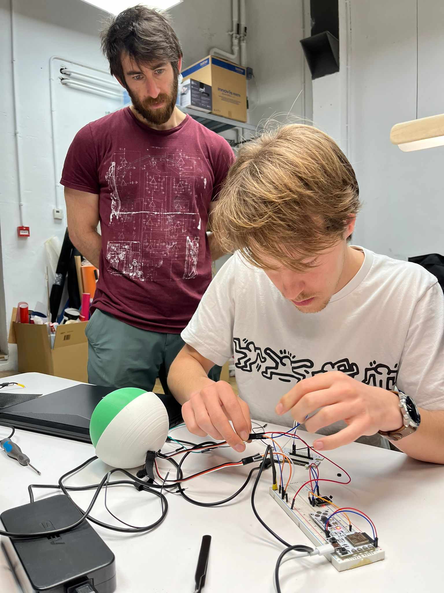
Since we are trying to build a robotic arm with Tony, this week felt like a good moment to get going with some servos, the Barduino and some wireless control!
We decided to use this spherical actuator by OB-3D as the base.
We 3D printed the different parts and files while working on getting the servos to function.
The code we wrote to control the servos functions via wifi and is here for the Python part and here for the Arduino part.
I learned how to create a simple GUI using Python and the QT library and to connect to the ESP32 microcontroller using wifi in order to control the servos. I followed this article for this.
Here you can see the servos moving!
Small preamp test
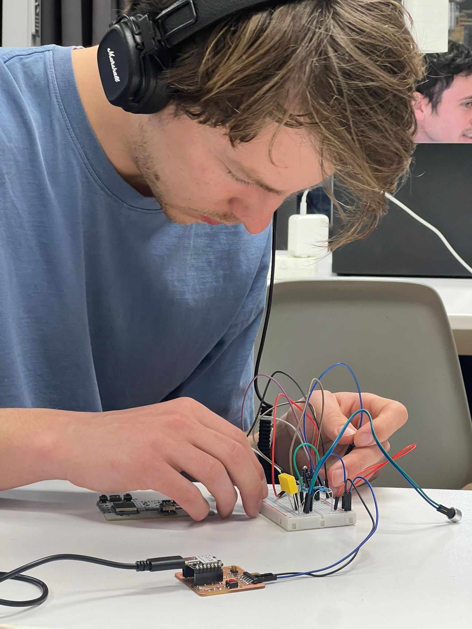
This week I also wanted to make a simple preamp circuit. I followed this instructables tutorial and used a breadboard. Next I would like to connect it to a microcontroller for some recording/playback possibilities as well as design a custom PCB for it.
Here is a short video of me whistling into the preamp and showing the results on an oscilloscope.
 The datasheet provides all the resources needed to understand the RP2040 at a low level, to really get into its architecture, how it works, all the pins and what they can and can't do, and how to make it all come together.
 Here you can see the servos moving!
 This week I also wanted to make a simple preamp circuit. I followed this instructables tutorial and used a breadboard. Next I would like to connect it to a microcontroller for some recording/playback possibilities as well as design a custom PCB for it.
Here is a short video of me whistling into the preamp and showing the results on an oscilloscope.
This week I also wanted to make a simple preamp circuit. I followed this instructables tutorial and used a breadboard. Next I would like to connect it to a microcontroller for some recording/playback possibilities as well as design a custom PCB for it.
Here is a short video of me whistling into the preamp and showing the results on an oscilloscope.