16. System Integration
This week we worked on system integration, how to make a final project come together and be beautiful!
For me, this took the form of trying to figure out how to mount my electronics and boards to a casing, as well as starting some designing work to improve my project.
Here is a link to the mood board for my project
Box design
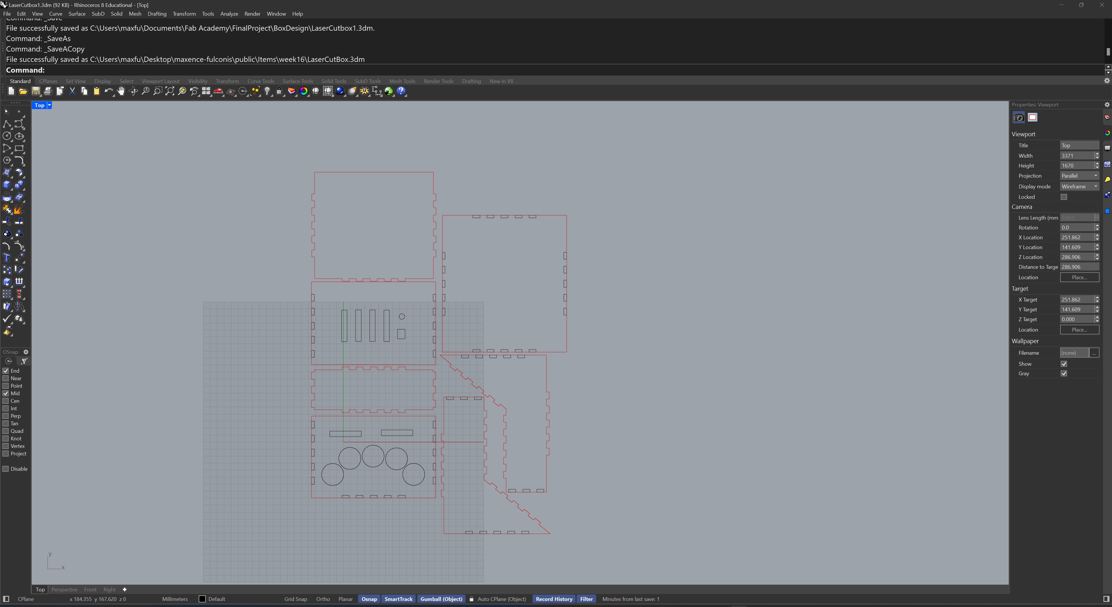
I decided to make a simple laser cut box for my synth, and so made a simple Rhino design for a box with cutouts taken from my PCB designs.
Here is the Rhino file for the box
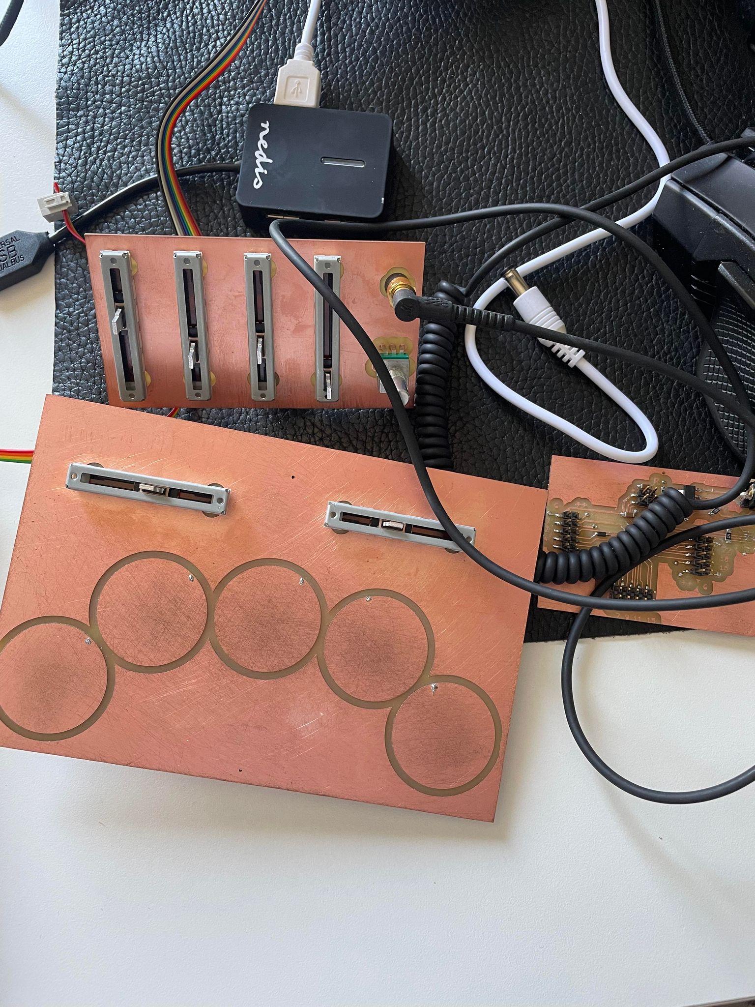
 Here are the electronics being tested and programmed :
 And the assembled box :
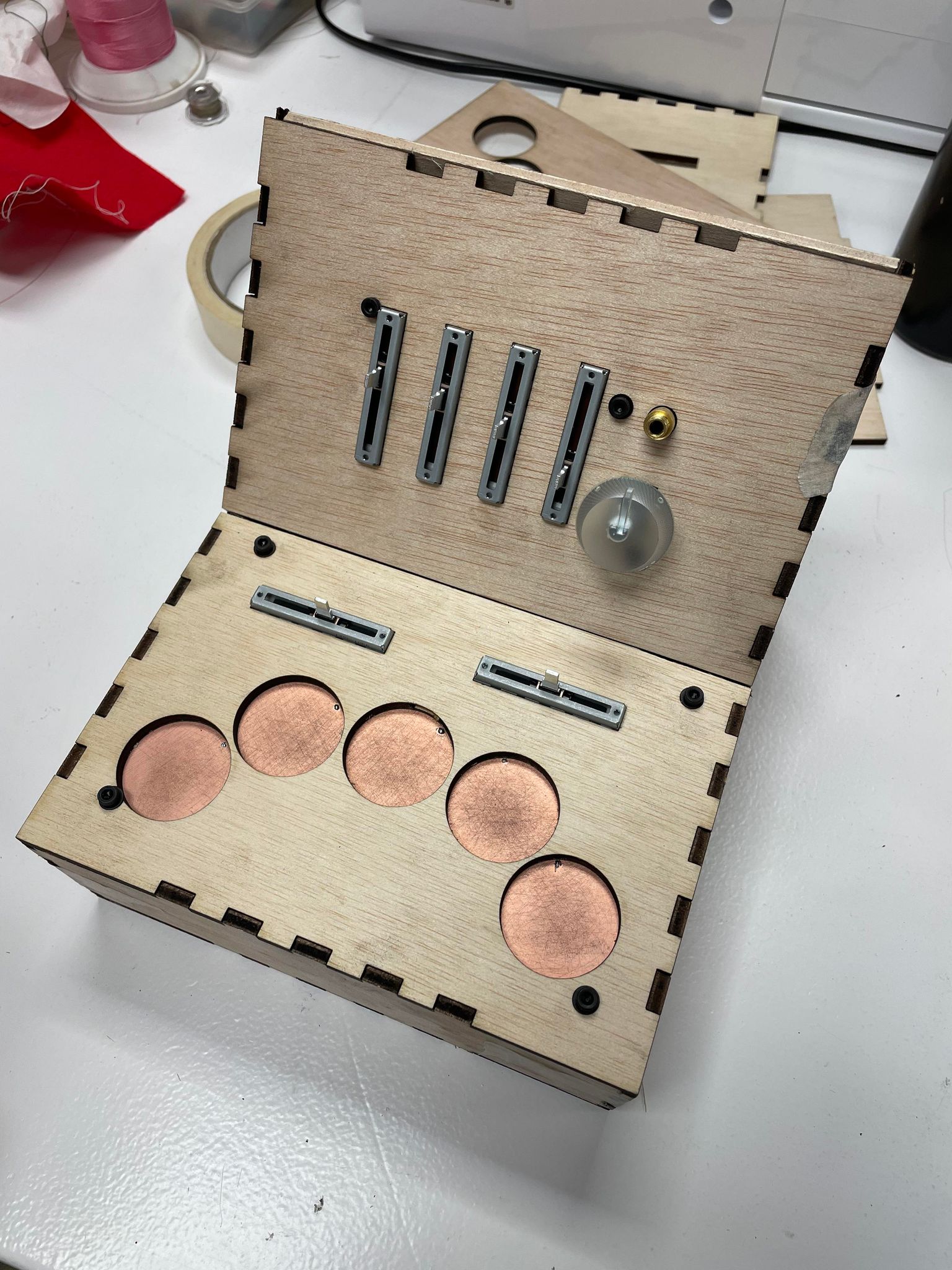 As you can see I screwed in the electronic panels containing the user-accessible functions, to make sure they were flush with the wooden front panels.
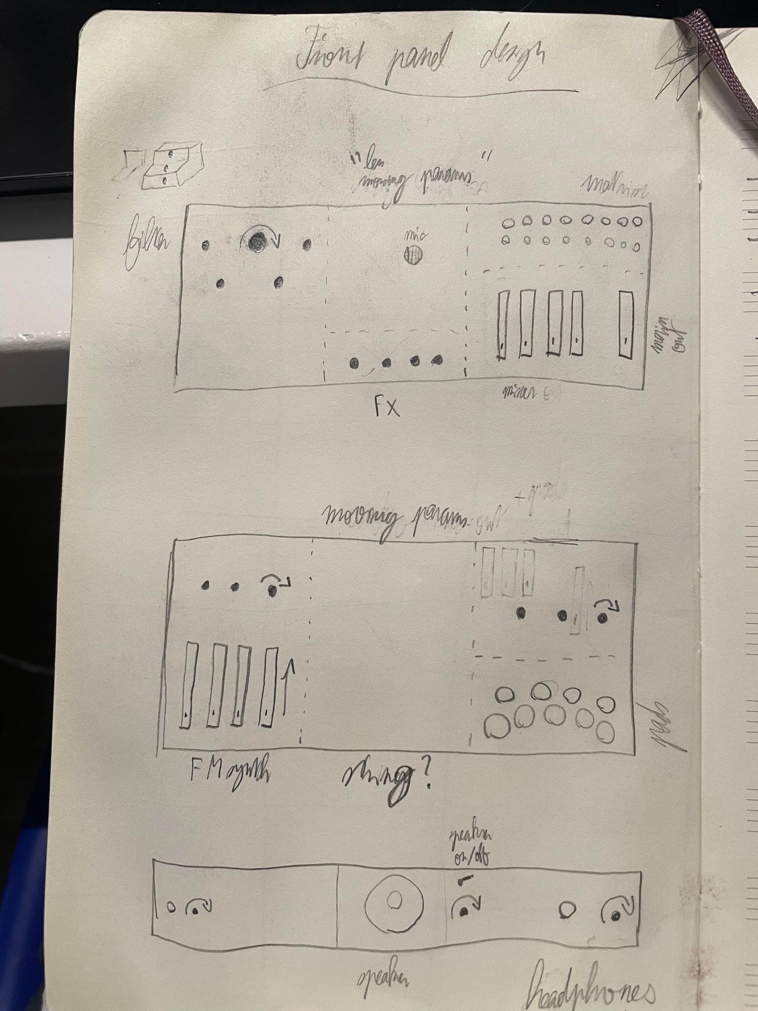
I had thought about design previously:
As you can see I screwed in the electronic panels containing the user-accessible functions, to make sure they were flush with the wooden front panels.
I had thought about design previously:
 The many ideas included adding acoustic components, which I also worked on this week, in the form of a plate reverb (a sheet of metal resonating with a driver and being picked up by a piezo mic), as seen below:
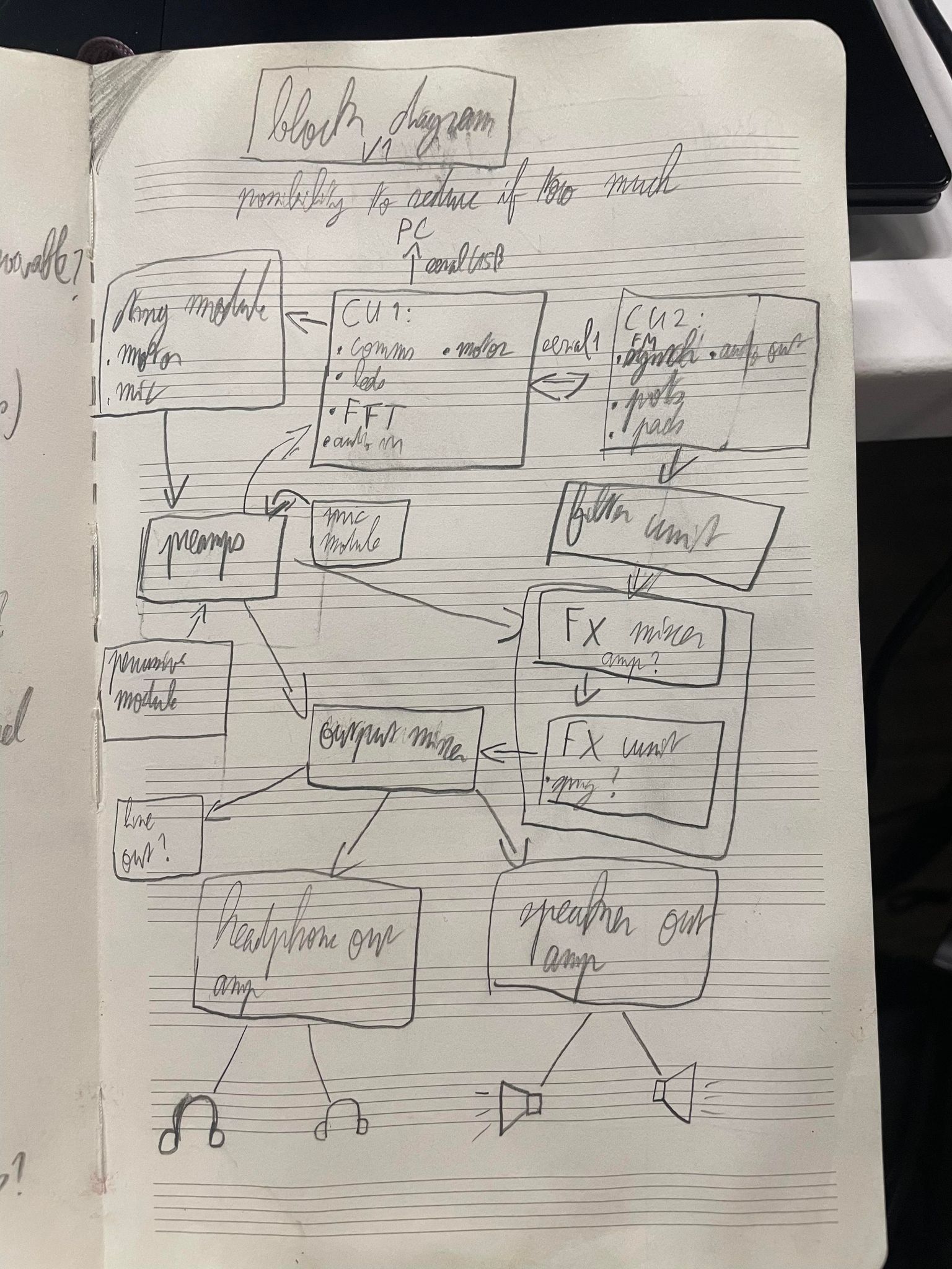
This was all brought together in a signal flow diagram, as seen below:
The many ideas included adding acoustic components, which I also worked on this week, in the form of a plate reverb (a sheet of metal resonating with a driver and being picked up by a piezo mic), as seen below:
This was all brought together in a signal flow diagram, as seen below:
 While I have not yet managed to create all the components (my attempts at a powered mixer resulted in frying 4 microcontrollers...), I am still planning to add more electronics!
Namely I would like to create a filter in order to add a bit more interesting dynamics to my sounds.
While I have not yet managed to create all the components (my attempts at a powered mixer resulted in frying 4 microcontrollers...), I am still planning to add more electronics!
Namely I would like to create a filter in order to add a bit more interesting dynamics to my sounds.
Wiring choices
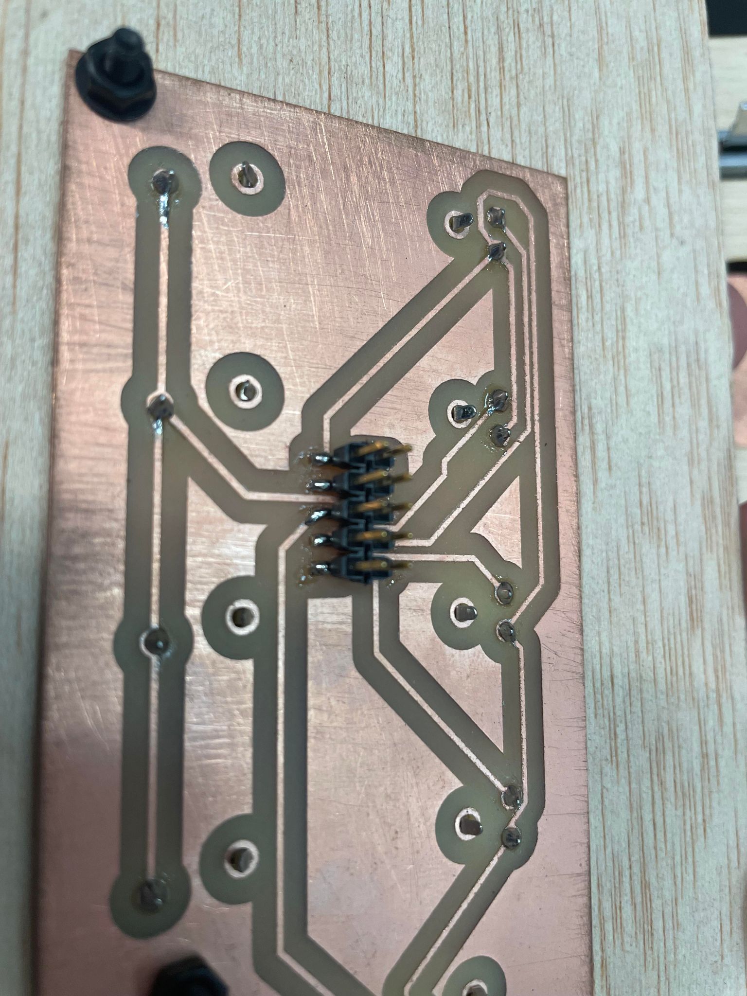
For wiring my project, I decided to standardise a connector amongst the different electronic components of the project.
This takes the form of a 10 pin header on each board (multiple 10 pin headers on the microcontroller boards)
 And a 10 pin cable to connect them between each other:
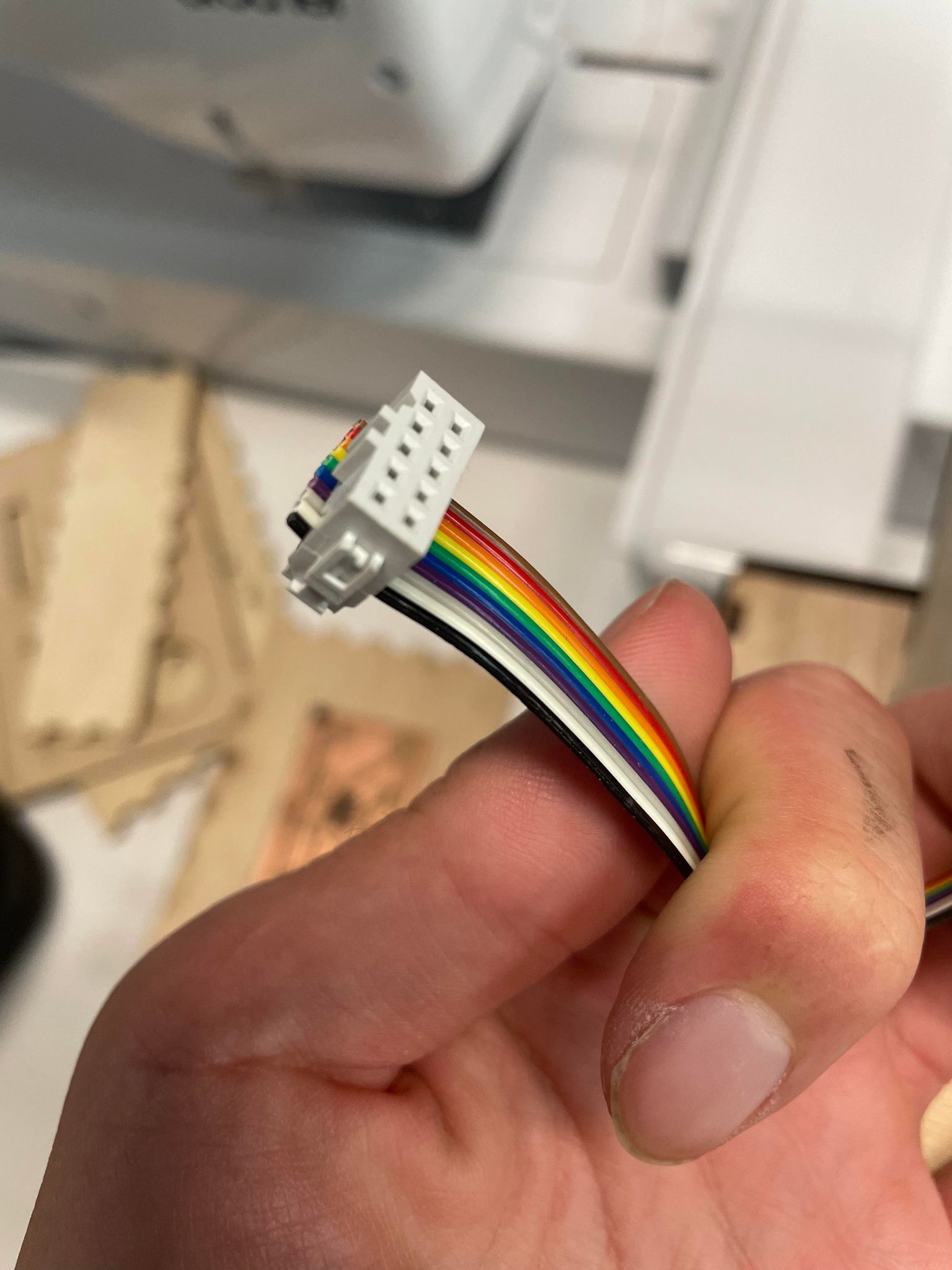 The cable is able to provide power through both a 3.3v connector as well as a connector attached directly to the output of the power supply, if the board needs more power.
Coding
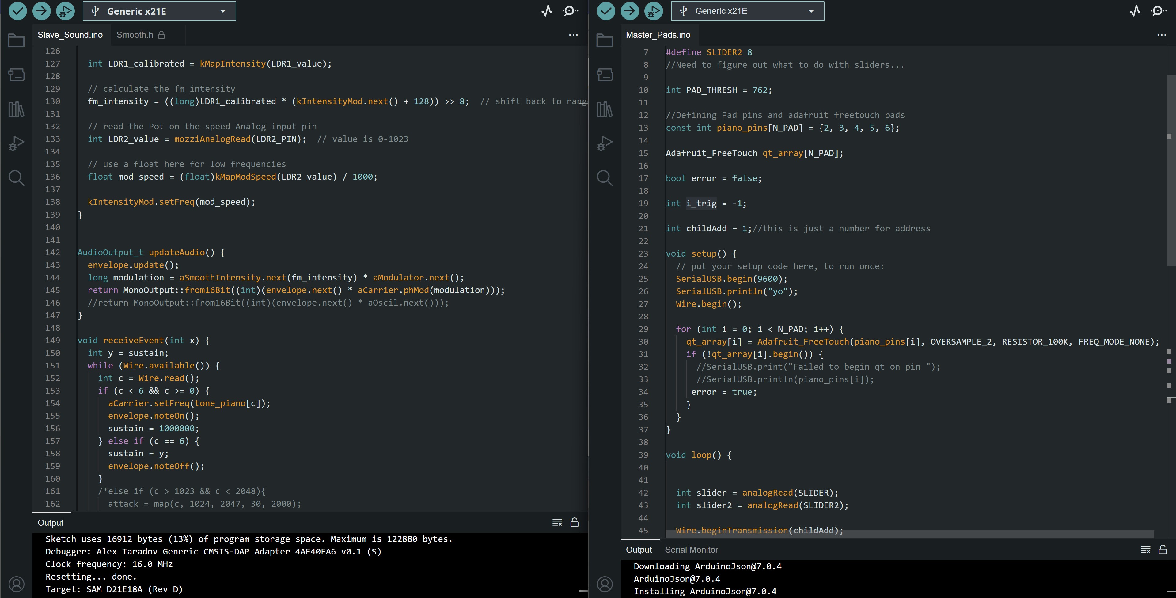
For coding and making the two boards communicate, I needed to use a networking protocol, so I went with I2C for ease of use and low complexit, as well as it being robust and synchronous and only requiring 2 (technically 3 if you count ground) connectors.
The code as of the video below is shared here for the parent controlling the capacitive pads and two sliders and here for the child controlling the sound output and most sliders
Playing the synth
To end this week, here is a small video of playing the synth in its box:
Going further
Left to do:
1. Add 3D printed slots for the other electronic boards not attached to the front panels
2. Remake the box with different materials (acrylic?)
3. Add colour-coding of different parts for better design
4. Add vinyl-cut stickers to define what each slider and function does
5. Add cutouts for power input to the box
6. Add more electronics (analog!) in different sections
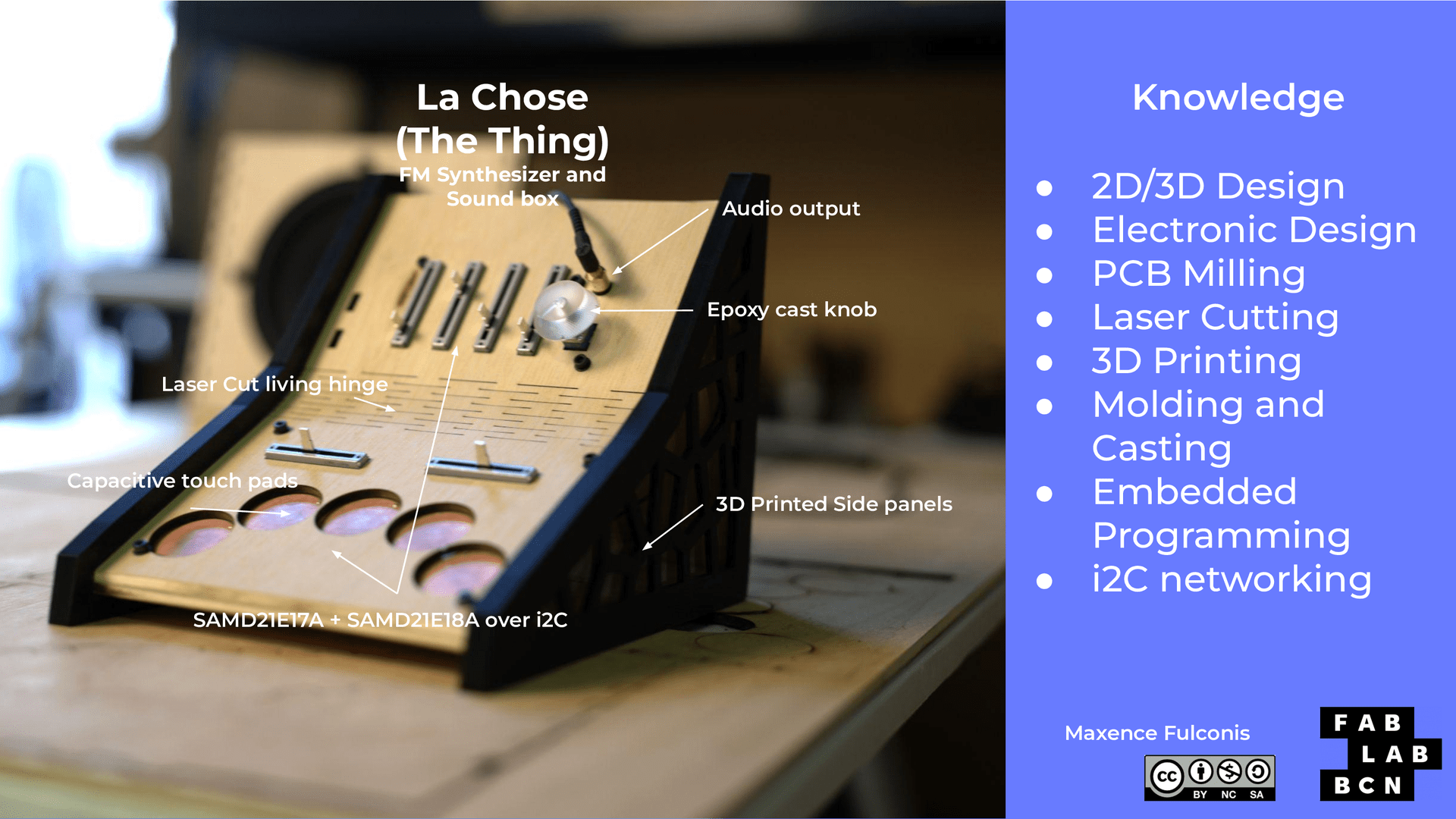
The end result of my final project, La Chose FM synthesizer, is explained in the slide and video below!