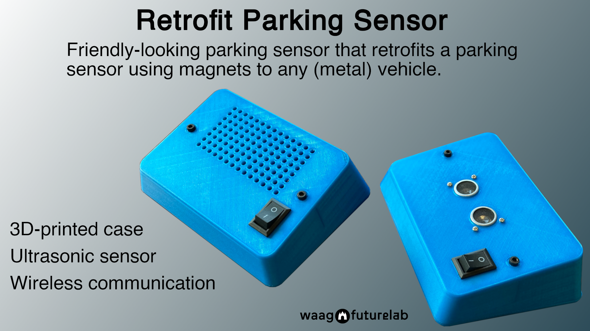
Final project
Retrofitting a Parking Sensor
Parts list
| Amount | Item | Description | Price |
|---|---|---|---|
| 2 | SAMD11C | The microcontrollers used on the boards. | € 3,32 |
| 2 | HC-12 SI4463 | Facilitates 2.4ghz communication. | € 16,00 |
| 1 | HC-SR04 | The distance sensors used. | € 1,99 |
| 58gr | Prusament PLA | The enclosure for the devices. | € 1,91 |
| 4 | MKSA-10x5-NI-N52 | Neodymium magnets holding the board to the car. | € 3,00 |
| 2 | 9V batteries | Batteries to provide 9 Volts to the circuit. | € 2,00 |
| 1 | Piezo buzzer | SMD piezo speaker. | € 0,45 |
| ? | Basic electrical components | Resistors, capacitors, switch, nuts, bolts, wires. | € 2,50 |
| - | Total | € 29,82 |
Process
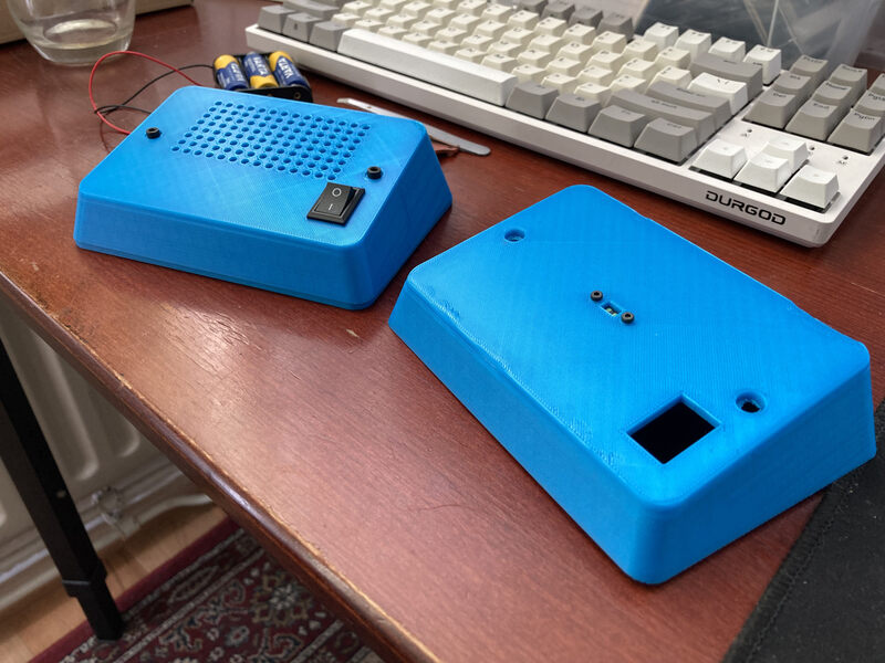
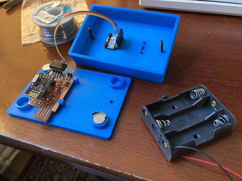
My idea for a final project is to create a device which can be used to add distance sensing to cars or other vehicles such as trailers which don’t have them. The device can be attached to the back of a car using magnets and has a silicone exterior on the back side in order to protect the car’s paint. It uses two distance sensors to detect whether or not a warning sound needs to be played. Red, yellow, and green LEDs are also used to show whether or not it is safe to continue reversing the vehicle. The device needs an ON/OFF switch. I will call the module that houses the sensor and sends its data the ‘sender’ and the one that houses the speaker and receives the data the ‘receiver’.

During the previous weeks I have tested multiple aspects of the system. I’ve worked with speakers in week 10 as well as week 11. In week week 11 I also tested the SR-04 distance sensor. In week 5 I did some experiments in printing PETG with the final project in mind, but finally I used PLA for ease.
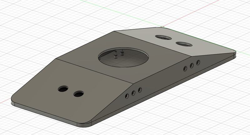
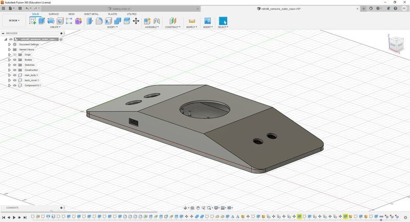
Enclosure
The first version of an enclosure design was made for the week 2 assignment. I developed the concept a bit further in the weeks following, and came up with this preliminary design by week 5.
So in the week following the 3D-printing assignment I set out to print the enclosure in PETG. This would be my first time printing PETG, but I had a lot of experience printing PLA, ABS, and ASA.
I was having a lot of issues with bed adhesion in the first layer, so after a bit of debugging I set the first layer speed to 50% after which things when smoothly. I printed the backplate I had designed and determined there were still many issues. Firstly, the dimension were not very well chosen. The X and Y-axis were quite large, much more so than they had to be for the required electronics. However, the height of the Z-axis was far too low. Eventually, I would run into issues even after doubling the height of the enclosure due to the space of the wires.
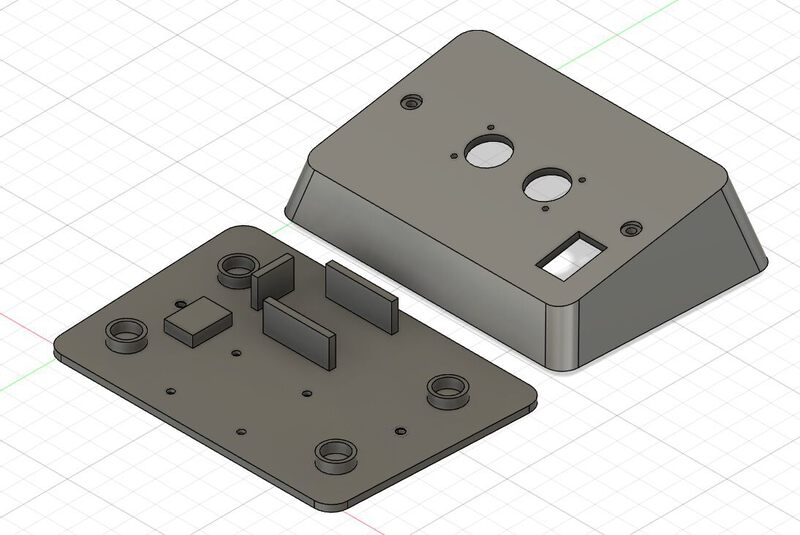
So my main tasks for the enclosure was to raise the height, create nutcatches for the nuts and bolts that hold the PCB, lower the width and length. Later I would also adapt the enclosure for the different components. For instance, I had assumed I would use two SR-04 ultrasonic sensors, however, in my final version I only used one.
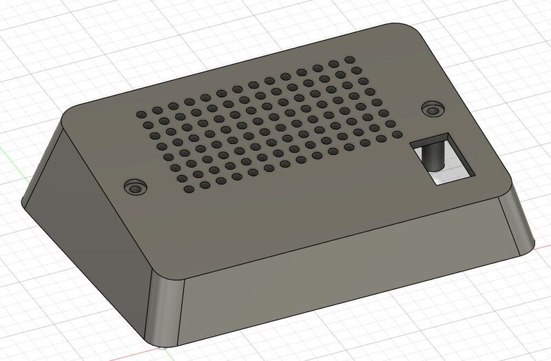
Later versions of the sender module had small adjustments in the dimensions as well as adjustments for a different sensor. In the image above a version is shown that was made for the VL53L1X. This sensor is much smaller and only needs a tiny opening in the enclosure to send a pulse through. The SR-04 that I finally used requires two larger openings.
Electronics
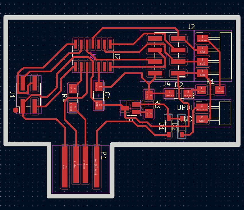
As expected I went through many versions of the sender and receiver module board, but mostly the sender as it has the most complex operation. One of the first issues was that I was not able to fit the library for the nRFL01 well as the VL53L1X on a SAMD11C. In addition, in the tests I did with the nRFL01 I was unable to establish a connection between the two boards. Following this, I started testing the HC-12 SI4463 Wireless Serial Port Module.
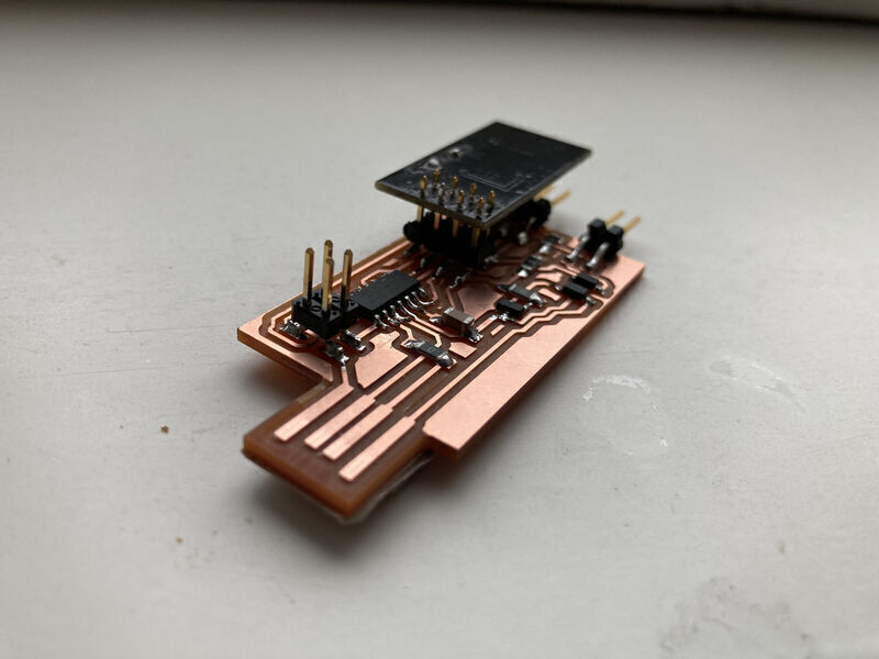
Below is a later version of the board shown in the image above, but with the USB connector oriented differently. Attaching the nRF24L01 is quite a hassle and especially removing it with the heat gun is annoying because of the 8 pins. A solution to this was to solder an 8 pin female header to the RF board. This way it can be removed if you need to access the PCB beneath it.
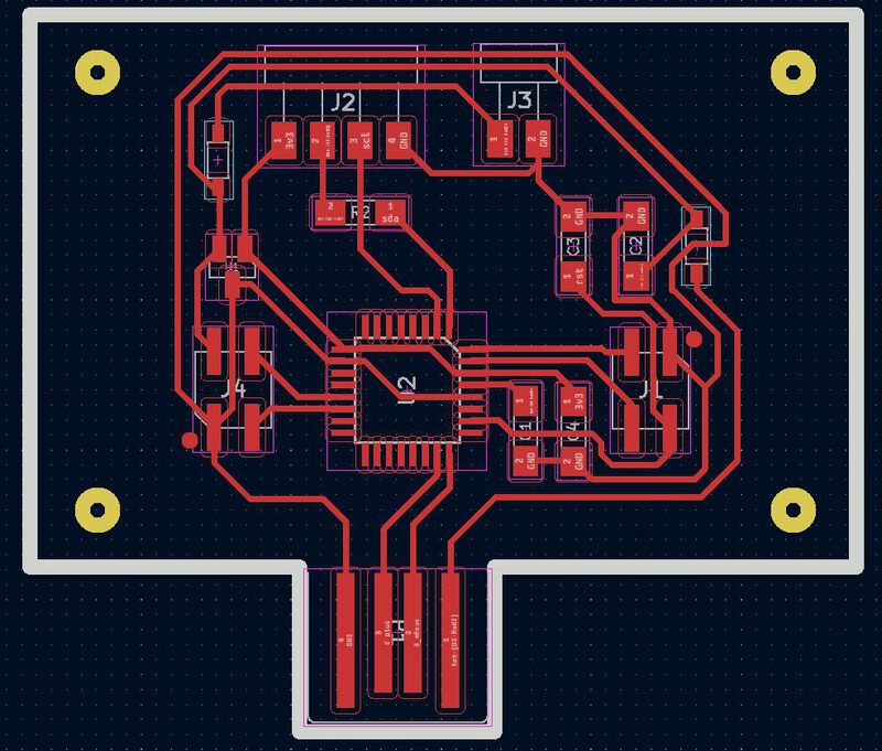
One of my main improvements was a SMD speaker that Bas had used in his output week. This saved me a bit of wiring and the speaker was smaller than the ones I had considered to begin with. Also this way the speaker was safely inside the enclosure instead of being visible from the outside.
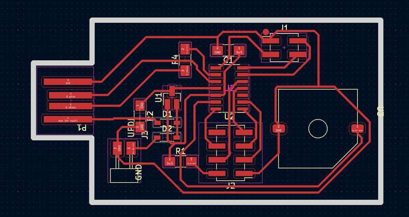
Quintin helped me design the SAMD21E version of the board. I had approached him as Henk was visiting the Prusa Factories in Czechia and Quintin had designed the SAMD21E Devkit. I used the Devkit as a starting point for the design of my board. Quintin had a look at the design and recommended a number of extra capacitors for noise removal and adding a pull-up resistor to the reset pin, as well as a 100nF to ground so it’s pulled up and smoothed out.
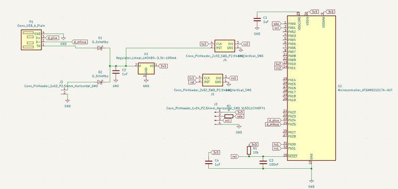
My final design for the sender board used a SAMD21E. However, I was not able to get the board to work. I was able to program the board with the bootloader, but could not upload any sketches and could not ‘see’ the board when connected to my PC. Therefore, I reverted back to an older version of the sender board which used a SAMD11C as well. However, this meant that I could no longer use VL53L1X sensor as the library for it would not fit on the flash of the SAMD11C. This meant that I would also have to revert to the HC-SR04 as it can be used without an I2C library.
Design files
Sender module
Receiver module
- Fusion design for the front
- Fusion design for the backplate
- KiCAD project for the receiver module
- Arduino code
Retrospective
My implementation of supply-side time management was not very structured, but I am very glad that after failing to get the SAMD21E version to work, I had an older version to fall back on. Luckily I could also use the connector on that board that I intended to use for the VL53L1X for the SR-04. Otherwise, I am not sure what I would have done. In any case it was good to have alternatives for the modules I intented to use. One of the largest challenges regarding time management is the fact that you are constantly putting out fires. Additionally, the steps in your project are heavily inter-related. For instance, you cannot test your code if your circuit is not working.
Documenting as you go is another guideline that I was not very consistent at following. For me, once time pressure because an issue, documenting-as-you-go is the first thing that goes out the window. Especially during the last few days, I barely took pictures of the process. However, I was lucky enough to have a working prototype with (almost) one day to spare, which meant that I had enough time to shoot some footage and edit it to a movie that I was happy with.
The area which I improved the most in was electronics. Eventually, I was quite confident in my ability to design and debug electronics. Nevertheless, there are still situation where a board you’ve designed is not working and you just can’t figure out why no matter how much time you spend on it. It is pretty frustrating but possibly a part of using this particular process.
In my code I’ve added outlier removal, meaning that if the difference in distance measured by the sensor changes by an amount which is too high, the measurement is disregarded. As the application is a parking sensor, it is reasonable there will be no object moving by meters in milliseconds. However, this is a resolution for a problem with the sensor measurement, which sometimes seems to be unstable. This was not the case VL53L1X. Additionally, the serial communication, while simple, is not always accurate. Sometimes, it does not send the newline and two measurements are concatenated. This might have been resolved by using a more robust protocol for communication.
Footnotes
- Legality
- [Basic example of samd11c with SPI/nRF24L01] https://roberthart56.github.io/SCFAB/SC_lab/Networking/networking/radio/index.html
License
Licensed under GNU-GPL