Week 12 - Input Devices
Analog signals can be amplified and is sometimes necessary. Resolution depends on amount of registers.
Group assignment
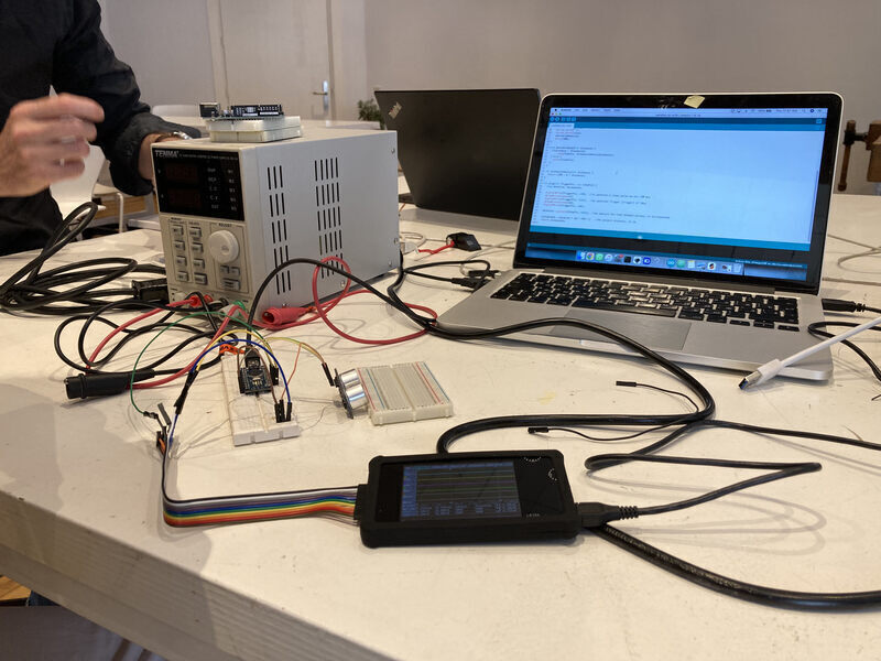
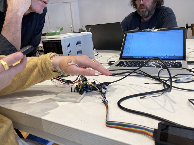
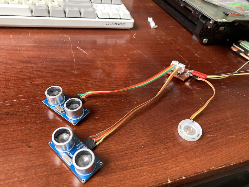
For the group assignment I worked with Paola and Sander to measure the signals being produced by a HC-SR04 sensor. We connected the sensor to an Arduino and uploaded a basic sketch which sends a pulse to the sensor and produces a distance measurement based on the response.
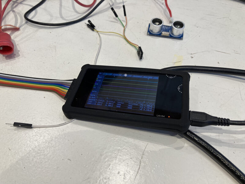
First, we looked at the signals using a logic analyzer. We used the LA104. It took us a long time to figure out how to start measurements and look at them. Finally, we were able to see the control voltage and the sensor’s response. We used a breadboard to connect the ground of the logic analyzer and the ground of the circuit to each other, as it is necessary to have a shared ground for the logic analyzer to pick up the signals.
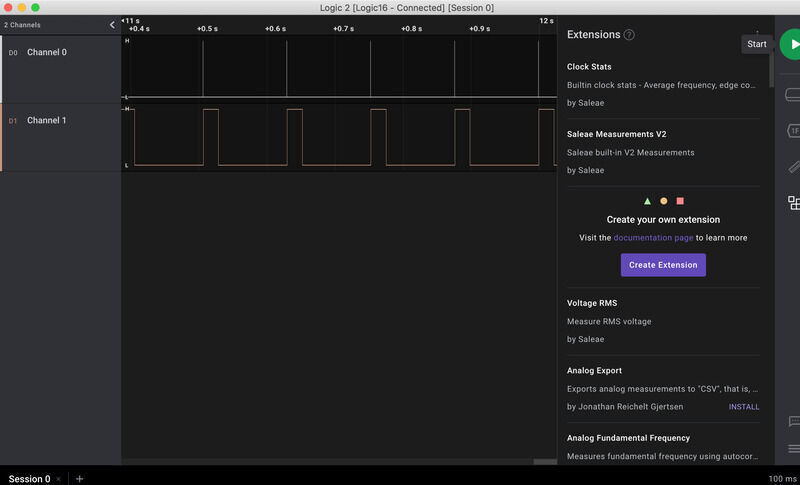
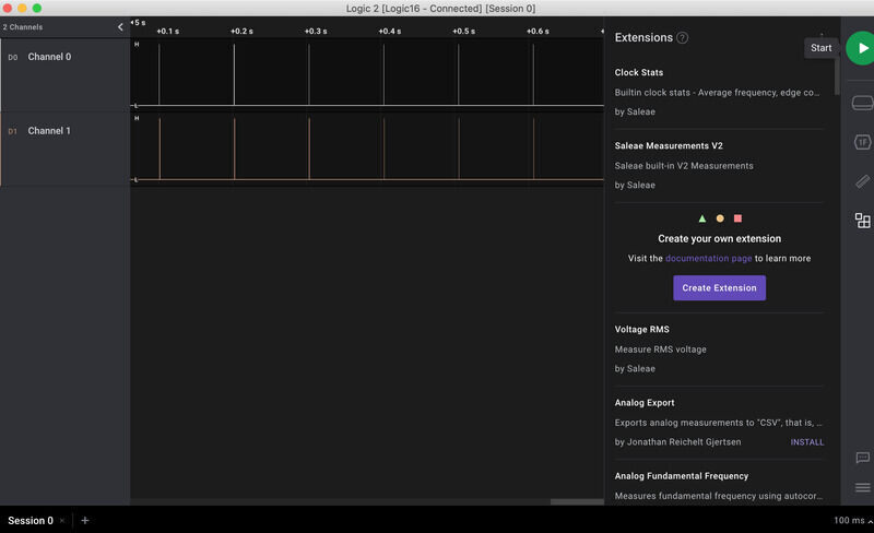
Then we switched to a Saleae logic analyzer and used Logic 2 to look at the signals. It was very intuitive to use and set up. We also tried to use Pulseview, but were unable to configure it correctly to work with the logic analyzer.
Individual assignment
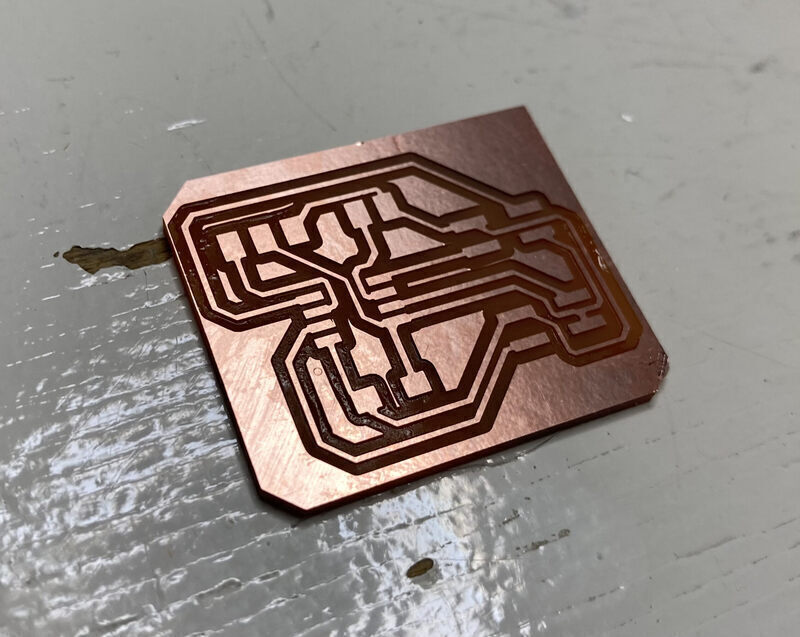
For the individual assignment I decided to make a new board which can connect to two HC-SR04 distance sensors. I designed the board over the weekend and milled it. The first time milling came out very rough because someone had put a broken mill back in the mill box. The second time milling went without issue.
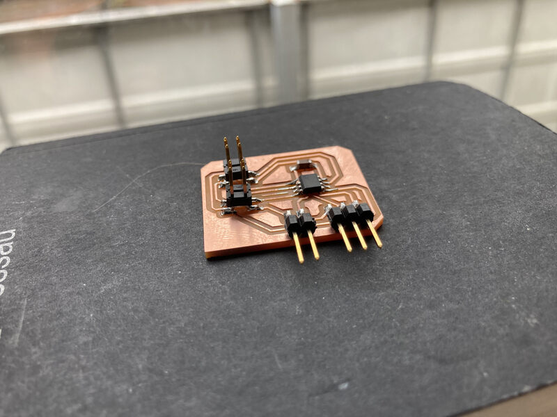
Following this I soldered on the components. I used a ATTiny 412-F, which becomes relevant later. Once the board was stuffed, I tried to program the board over UPDI using my SAMD11C serial interface. I was again unable to program and was receiving a UPDI initialization error. After measuring the connections on my board using a multimeter I was unable to pin-point the issue.
I discovered on Monday that I was having issues programming using my SAMD11C serial board, so I remade the board. Finally, I was able to program boards I had previously made, but I still wasn’t able to program the board I had designed for this week. A long day of testing seemed to indicate that there was an issue with the new ATTiny412-F that I had used. Only after swapping it out for an ATTiny412-N was I able to program.
It took some time to tweak the code, but eventually the code below gave the intended result.
//Fab Academy 2022 - Jonathan Blok
//Ultrasonic sensor
//SAMD11C

const int echoPinLeft = PIN_PA2;
const int triggerPinLeft = PIN_PA1;
const int echoPinRight = PIN_PA6;
const int triggerPinRight = PIN_PA3;
const int speakerPin = PIN_PA7;

void setup() {
   Serial.begin(9600);
   pinMode(triggerPinLeft, OUTPUT);
   pinMode(triggerPinRight, OUTPUT);
   pinMode(echoPinLeft, INPUT);
   pinMode(echoPinRight, INPUT);
   pinMode(speakerPin, OUTPUT);

   tone(speakerPin, 392, 300);
   delay(300);
   tone(speakerPin, 466, 300);
   delay(300);
   tone(speakerPin, 349, 300);
   delay(300);
   tone(speakerPin, 262, 300);
   delay(300);
}

void loop() {
   int cmLeft = ping(triggerPinLeft, echoPinLeft);
   int cmRight = ping(triggerPinRight, echoPinRight);
   processDistance(cmLeft, cmRight);
   delay(50);
}

int ping(int TriggerPin, int EchoPin) {
   long duration, distanceCm;

   digitalWrite(TriggerPin, LOW);  //to generate a clean pulse we set LOW 4us
   delayMicroseconds(4);
   digitalWrite(TriggerPin, HIGH);  //we generate Trigger (trigger) of 10us
   delayMicroseconds(10);
   digitalWrite(TriggerPin, LOW);

   duration = pulseIn(EchoPin, HIGH);  //we measure the time between pulses, in microseconds
   distanceCm = duration * 10 / 292/ 2;   //we convert distance, in cm

   return distanceCm;
}

void processDistance(int cmLeft, int cmRight) {
  if(cmLeft < 30 && cmLeft > 1){
      tone(speakerPin, 262 - cmLeft, 500);
  }
  if(cmRight < 30 && cmRight > 1) {
      tone(speakerPin, 294 - cmRight, 500);
  }
}
Conclusions
- It is hard to debug code without a serial output, perhaps I should try to make a programmer which allows simultaneous serial and UDPI connections.
- Every week that involves electronics involves me debugging boards I have previously made.
- Either the code or the sensors seem to make the output be less than reliable, this setup wouldn’t work for a car.
- I need to consider the footprint of connectors as well, as the two sensor connectors were quite close together.