CAD Programs Comparison
I’ve gotten to know a number of CAD programs during my time at FAB Academy and earlier. My first experience is with OpenSCAD which was quite accessible for me as my background is programming. Using a mouse is recommended by Michelle. In the past I’ve also worked with SketchUp and Tinkercad. Blender is maintained by a foundation in Amsterdam. Good for organic design.
OpenSCAD
Programming language-based CAD design tool. I’ve used this tool for projects in the past, and although it is a good tool to work with basic shapes quickly, I’ve found that the codebase becomes quite messy and it is hard to keep oversight when the models become complex. There are a number of ways to remedy this. It is good practice to use modules and functions when there is a piece of code which has a unified function. A function is a piece of code which performs an action e.g. calculation, and a module is a piece of code that models a section of the model. Additionally, there are many libraries available to work with standards, such as metric bolts and nuts.
Tips
- View > Thrown Together can show shapes that are being subtracted.
- Hashtag / pound sign can highlight a shape.
- Define as many variables as possible at the top, but don’t over-do it. No need to define 2, when dividing by 2.
Freecad
Babken gave us a nice tutorial on how to use Freecad. Freecad is a free and open-source alternative to proprietary tool such as Blender and Fusion. It seems very stable and is easy to install and setup. Although it is not very easy to use and has a steep learning curve. In my experience FreeCAD was very iffy, gave many errors, and things sometimes happened without me intending to do them. It seemed very powerful when working with parameters and creating different copies. The tools seems pretty unintuitive and complex, but there seem to be very many possibilities. Also the workflow looks very difficult, and you need to know exactly where to find the functions you need for a task. The errors are not as informative as in other tools.
Showcase shows existing projects, extruding is called padding in Freecad, construction lines need to be made. To consolidate a model set Polar pattern Refine to true. Shift + R to set radius constraint for a circle.
Workflow
- Create spreadsheet with parameters and most importantly add aliases for parameters, otherwise you will not be able to find them. You can find them later by calling from the Spreadsheet class e.g. Spreadsheet.part_height.
- Create a body
- Create a sketch
Autodesk Fusion 360
The Autodesk Fusion lesson was very interesting and informative, but also a lot to digest so I will probably forget some things that I learned. I like Fusion as a CAD tool, it is sometimes intuitive which I did not experience in other tools. By creating shapes, extruding them and combining them as well as other operations you can quite quickly create desired design objects. Also constraints can be easily added, but it is best to define them at the start of your design.
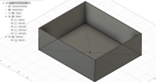
As part of the lesson we created a box which has slots to show how to design the slots, as well as expand the designed box to a design that can be laser-cut. Finally, Michelle showed us how to render the model in an animation for documentation purposes.
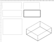
Render for documentation purposes, you can change the finish, background, decal.
Drawing > From Design to make a technical drawing or file for laser cutting.
Fit point spline for flowing, organic lines.
Workflow
- Make parameters first, do calculation Excel-like.
- Then create 2D sketches for the surfaces that you want use.
- Extrude the shapes to create 3D shapes.
Observations
- For laser cutting you need to take the sketch squares and subtract them from the corners (box_height / 2).
- Then use the ‘combine’ operation to and use the two orthogonal walls as tools to subtract from each wall.
- Animation is also used for documentation purposes, but you also need to turn your model into components in the ‘Design’ view. Then go to animation and use the timeline to ‘explode’ components.
- Section analysis shows a cut section and adds a folder which shows the section you created.
- Threaded cylinder, create > thread.
- Tangent constraint can allow you to move something along a cylinder.
- Slicer for Fusion 360 can slice your models into slices for laser cutting.
- Construct offset plane allows you to create a sketch above a sketch.