Week 13 - Networking
Notes
- SPI is faster but more error prone. Good for transmitting large amounts of data.
- I2C is used for communication between MCs.
- Serial2Wireless is a protocol that uses a wireless transmitter to transmit in such a way that the MC only needs to talk serially.
- UART/UPDI is used to program our boards, but was not really discussed much.
Group assignment
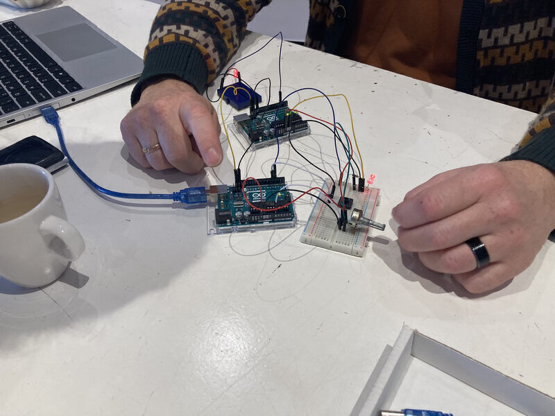
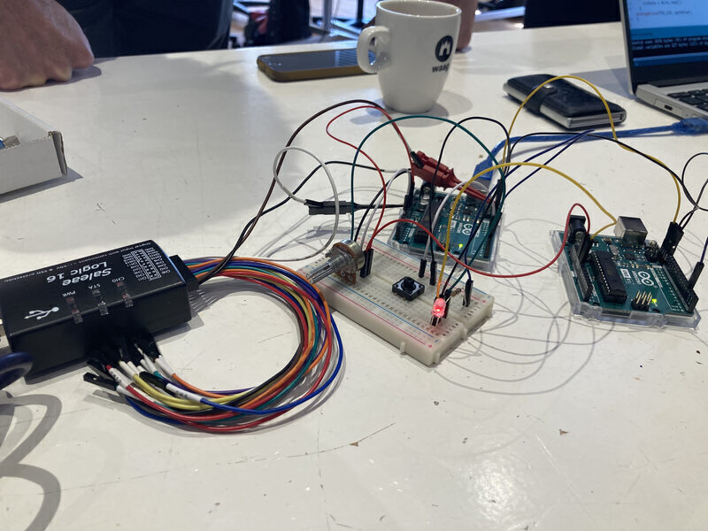
For the group assignment we worked together to connect two projects that were made previously. The project consisted of two Arduino UNOs and a breadboard. On the breadboard an LED was being controlled by a potentiometer. The voltage being going through the LED was then sent to the other board via I2C. We used a logic analyzer to see the data that was being sent over I2C.
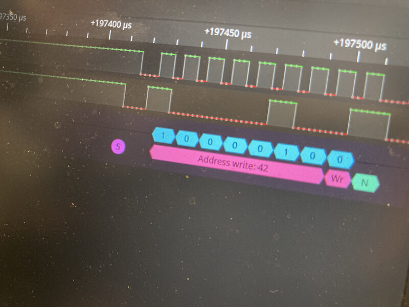
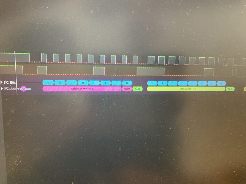
While looking at the code we noticed a mistake that had been made by Erwin. He had bitshifted the entire address to the left in order to account for the R/W bit, but after looking into the protocol it turned out that the protocol already handled this. However, because he did the bitshift on both ends of the communication, the communication was unaffected. However, the address being used was not 42 as he had intended but rather 42 bitshifted left which would be 84.
Wire.beginTransmission(NODE_ADDRESS <<< 1);
Individual assignment
I spent a long time thinking about what I would find interesting to make. I didn’t have a particular purpose in mind so I decided to try to design something kind-of generic. A board that I could use to connect to a simple voltage-output sensor, and it would send the sensor signal via I2C. I started designing the board I had in mind. First step, do NOT put the UPDI pins in the wrong order.
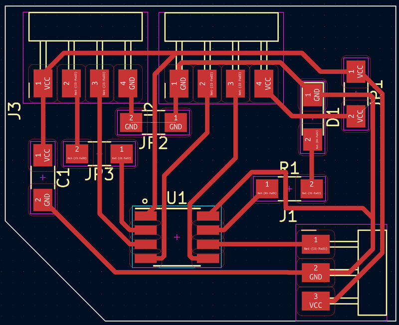
Designing the PCB was a little tricky because of all the connections to connectors. I ended up using three jumpover resistors. Not sure if I could’ve done without them but the board doesn’t look too bad to me. I added the jumpover resistors as bridged jumpers in the schematic mode, but still the nets were not connected and the design rule checker complained about them.
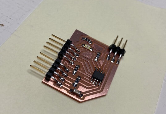
After stuffing the board I uploaded a small piece of code that turned on the LED if the sensor output was below a certain threshold. The code worked so I knew that at least the sensor, UPDI, LED parts of the board was functional.
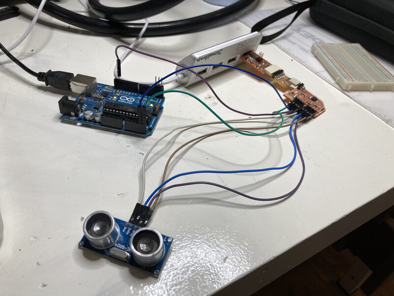
Finally, I connected the board to an Arduino UNO in order to send the sensor data using the I2C protocol. I looked up what pins on the Arduino UNO were needed to use the protocol. Apparently, only A4 and A5 can be used, but I’m guessing that if you want to connect many devices via I2C you would daisy-chain them.

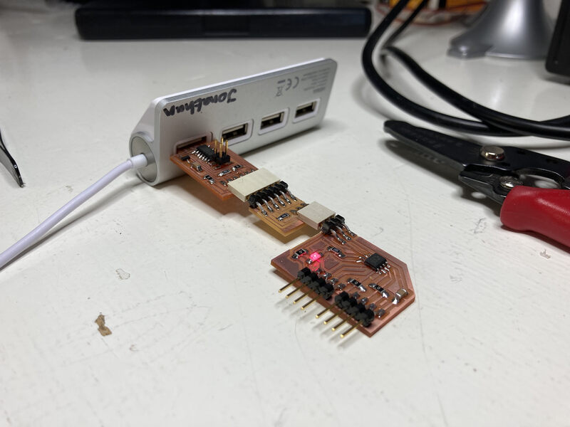
During the process of debugging I had to upload multiple versions of the host/node sketches. Therefore, the node board was being powered via the SAMD11C serial board and the Arduino was powered normally via USB. Because of this, I didn’t need to connect the VCCs of the boards.
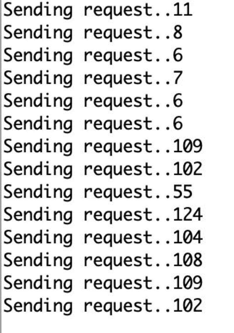
Eventually, I got the code to work. Only the node needs an address, because if you call begin() without an address as argument, Arduino assumes that you are the host. Excluding the read-write bit used in I2C leaves 7 bits to send measurement data, so this would only work up to 27=128.
Code for the host
#include <Wire.h>

#define NODE_ADDRESS  0x42

void setup() {
  Serial.begin(9600);
  Wire.begin();
  Serial.write("Setup done..");
}

void loop() {
  Serial.write("Sending request..");
  Wire.requestFrom(NODE_ADDRESS, 1);

  while (Wire.available()) { // peripheral may send less than requested
    int c = Wire.read(); // receive a byte as character
    Serial.print(c);         // print the character
  }
  Serial.print("\n");

  delay(1000);
}
Code for the node
#include <Wire.h>

#define NODE_ADDRESS  0x42

//Fab Academy 2022 - Jonathan Blok
//Ultrasonic sensor
//ATTiny412

const int echoPin = PIN_PA7;
const int triggerPin = PIN_PA6;
const int ledPin =  PIN_PA3;// the number of the LED pin

int ledState = LOW;
int cm = 0;

void setup() {
   pinMode(triggerPin, OUTPUT);
   pinMode(echoPin, INPUT);
   pinMode(ledPin, OUTPUT);

   Wire.begin(NODE_ADDRESS);
   Wire.onRequest(dataRequest);
}

void loop() {
   cm = ping(triggerPin, echoPin);
   processDistance(cm);
}

int ping(int TriggerPin, int EchoPin) {
   long duration, distanceCm;

   digitalWrite(TriggerPin, LOW);  //to generate a clean pulse we set LOW 4us
   delayMicroseconds(4);
   digitalWrite(TriggerPin, HIGH);  //we generate Trigger (trigger) of 10us
   delayMicroseconds(10);
   digitalWrite(TriggerPin, LOW);

   duration = pulseIn(EchoPin, HIGH);  //we measure the time between pulses, in microseconds
   distanceCm = duration * 10 / 292/ 2;   //we convert distance, in cm

   return distanceCm;
}

void processDistance(int cm) {
  if(cm < 30 && cm > 0){
    ledState = HIGH;
  } else {
    ledState = LOW;
  }
  digitalWrite(ledPin, ledState);
}

void dataRequest() {
  Wire.write(cm);
}
Conclusions
- There must be a better way to add jumpover resistors, perhaps a plugin.
- Sometimes things can go smoothly (1/13 chance).