Week 5 - 3D printing
Yesterday and today we had our introduction to 3D printing. 3D printing is not completely new to me, as I’ve used two 3D printers in the past. These two printers are the Ender 3 Pro and the Prusa Mini+.
Here are some concepts that were introduced to us in the introductions:
- Overhang, it is possible within certain boundaries to print onto nothing as long as there is a supporting structure to print beside.
- Overextrusion or underextrusion happens when too much or too little filament is pushed out of the nozzle.
- Heat creep is when the heat of the nozzle creeps back up towards the beginning of the bowden tube.
- Bed adhesion determines how well a material sticks to the build plate.
- Warping happens when parts of a print cool unevenly, and happens more with some materials than others.
- Part cooling is the cooling of the part after printing, done by a fan and by ambient air.
- Stringing are thin strings of filament between bridges and gaps.
- Bed levelling is making the build plate even, done manually or automatically.
- Material properties: PLA is relatively environment friendly, easy to print, not very robust, foodsafe. ABS/ASA/PETG are stronger less environmentally friendly plastics, not foodsafe, need to be printed at a higher temperature. ABS/ASA is prone to warping and has bed adhesion problems. All plastics breakdown in UV light.
Group assignment
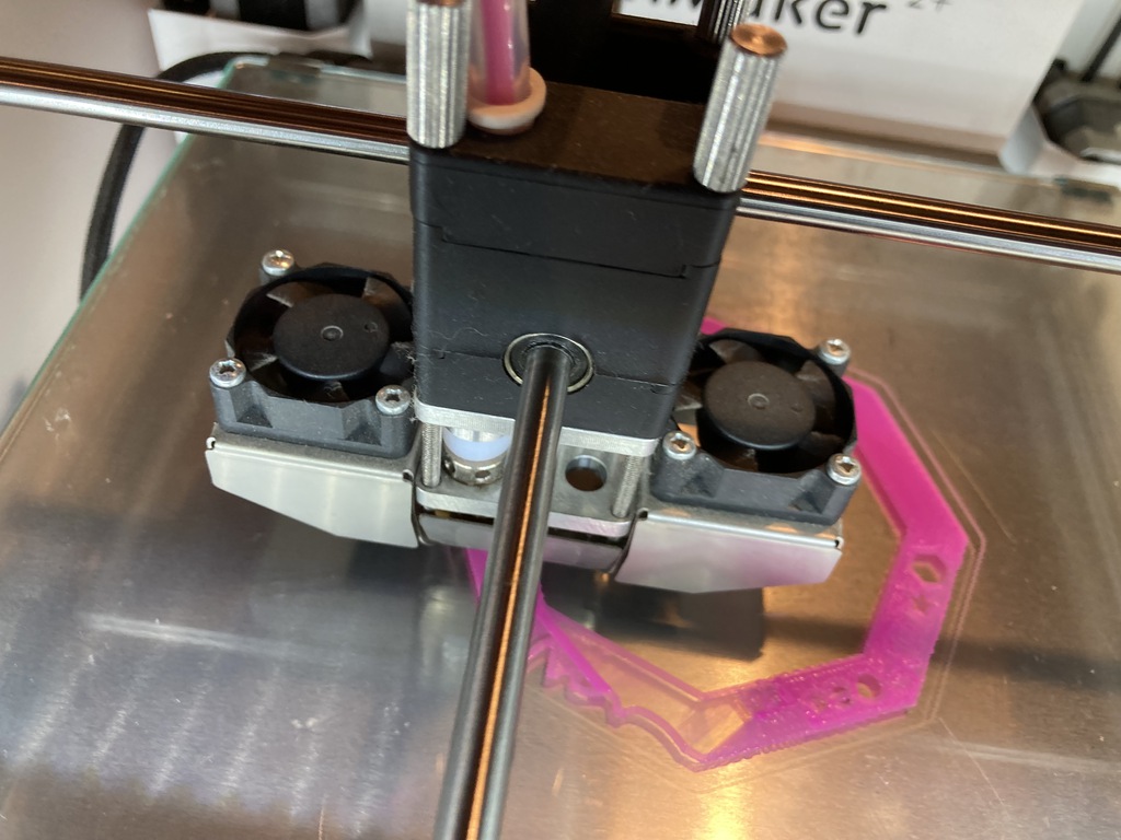
As I was familiar with the other two printers, I was going to work with the Ultimaker 2+
What was different on the Ultimaker 2+ from the other printers that I had worked with was that the bed moves on the z-axis rather than the head. Also, during the calibration of the z-axis, there was one calibration on the back of the print plate, and two at the front. We downloaded this printer testing model and sliced it using Prusaslicer. But before we could proceed with the printing, we had to calibrate the printer.

The printer has a calibration wizard on-board. It goes through the steps of bed levelling using messages display on the printer screen. First the printer asks you to move the bed towards the nozzle up to a distance of 1mm. The back of the bed is levelled first using the step motor controlling the spindle. Then the front two spring-loaded screws are tightened to the same distance. Following this, the printer is calibrated more precisely. This we did with a piece of paper.

After calibration we continued with our testing model. The Ultimaker uses a different filament width from the other two printers. The filament used is 2.85mm and the other two printers use 1.75mm. We had a few filaments to choose one and we went with the bright pink.

After a small issue with the extrusion, we were able to get started with the print.

The model came out reasonably well. We used the default settings for ‘Generic PLA’ in Prusaslicer, and I think the temperatures are a little too high. This might help with some of the stringing, but overall we were satisfied with the result.


Compared to the other printers, the results for the Ultimaker were comparable to the Ender 3. The detail on the Prusa MK3 was much better. However, there is no sense in comparing results without considering the settings. We decided to print our model with a 0.20mm layer height.
Individual assignment
Design something and print it
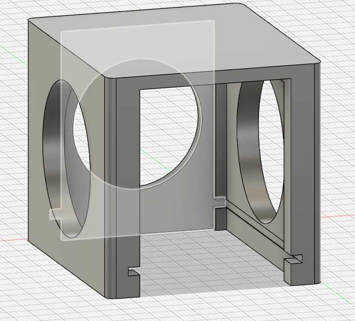
I had a lot of trouble working on this assignment as the assignment was very broad. Design something that can not be made subtractively. My first idea was to create an enclosure for the LED board we made in the introduction week. Then the enclosure could be printed using a clear material to test the LED diffusion. My idea was that by diffusing the light of the LED the displayed text would become more visible.
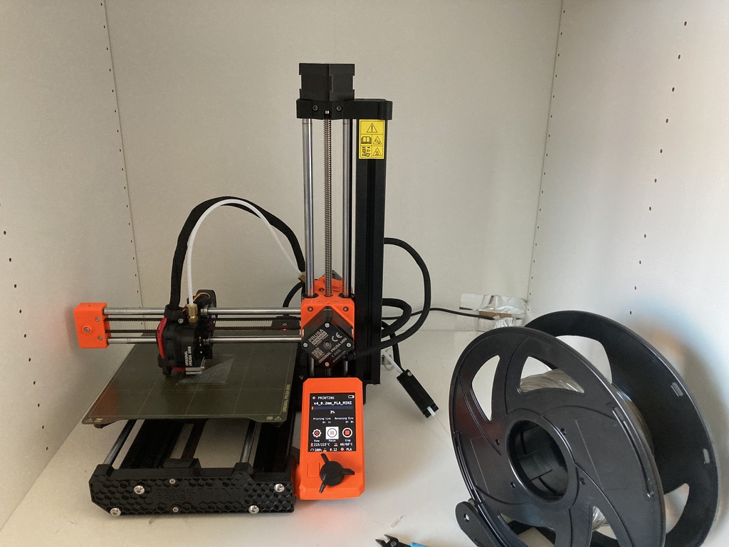
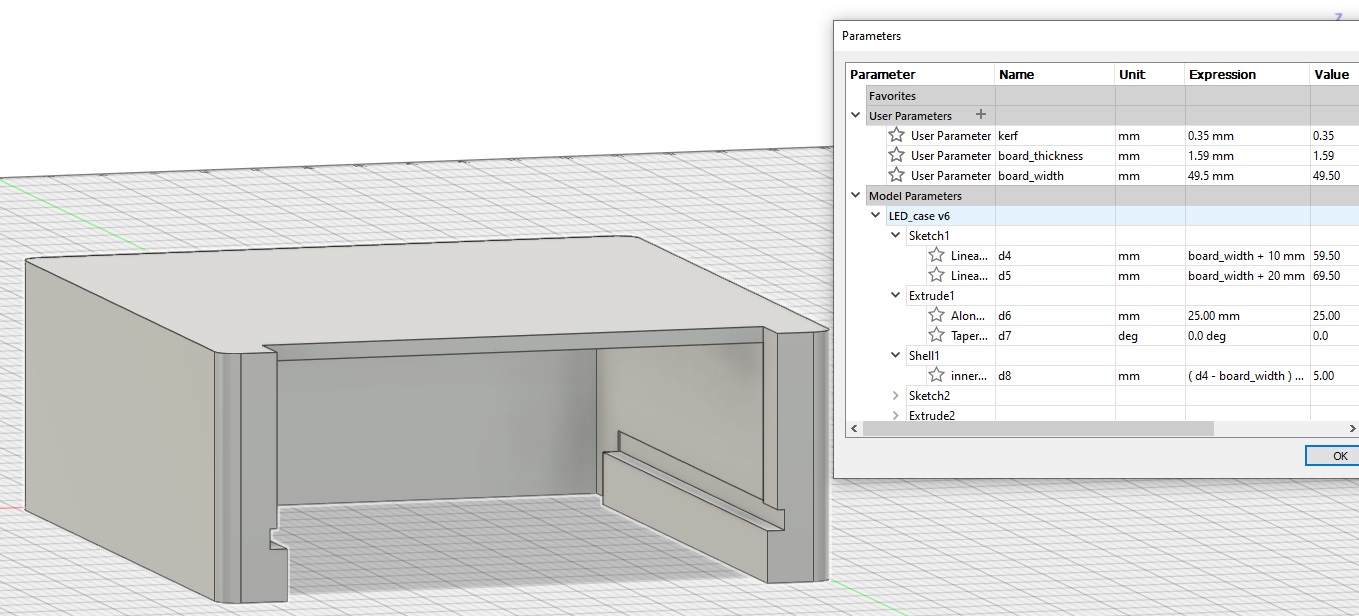
I decided to do my first prints on a printer that I have at my workspace, which is a Prusa Mini+. I modelled the general shape of my design in Fusion and used parameters to fill in the exact dimensions later.
I loaded the filament and started to print.
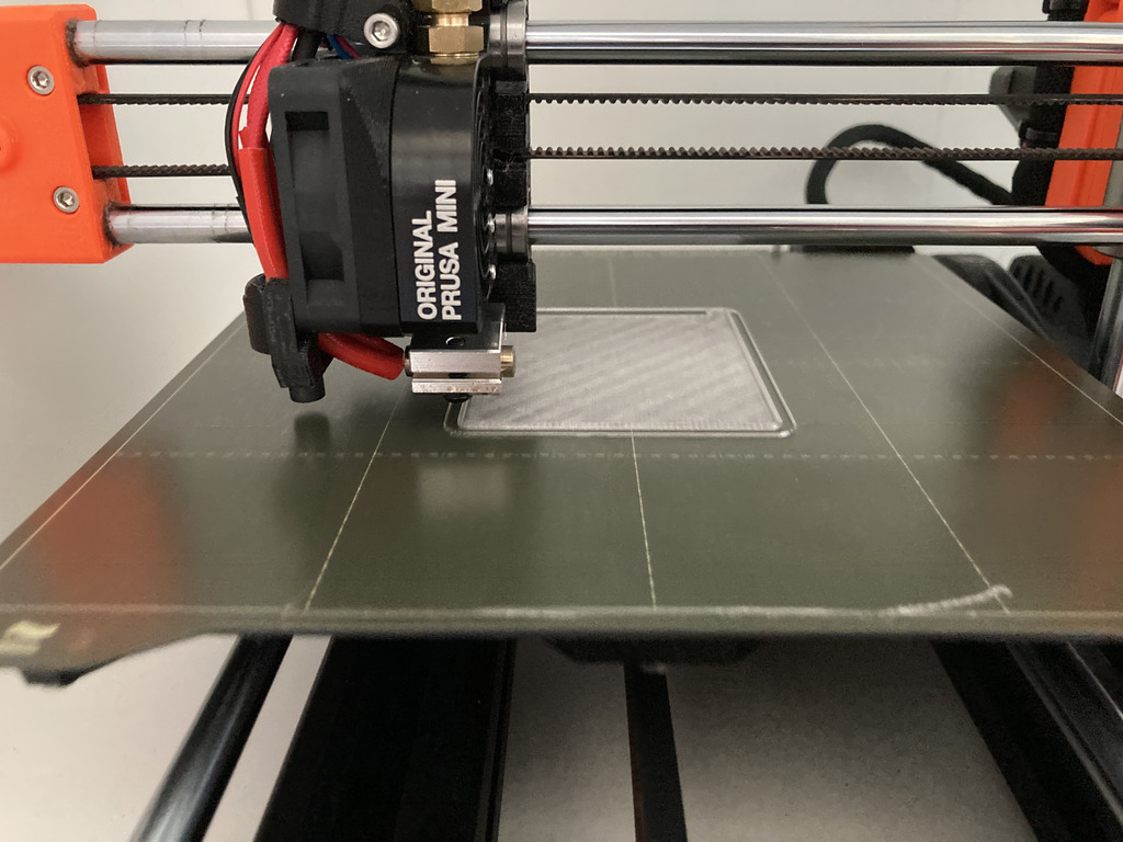
I printed this model using the default settings for ‘Generic PLA’. There was quite a lot of stringing so I reduced the filament temperature by 15 degrees.
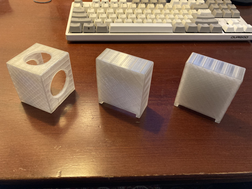
My first version was way too high. I cut out holes from the side walls of the design in order to speed up the printing, as I knew that I would probably need multiple iterations. From previous printing experiments I knew that there was a kind of kerf when 3d printing as well. Inner spaces tend to be a bit smaller in the print than on the model. I used this failed model to gauge the kerf at 0.35mm.
I was quite happy with the outcome, the board fits in nicely and you don’t need to force it. Taking it out is easy, the tolerances give it just the right amount of grip. However, a drawback is that the orientation of the board means that either the VCC and ground pins are hard to reach, or the LEDs aren’t centered nicely on the enclosure.
It took me three tries to get the design and settings right. The design file can be found here.
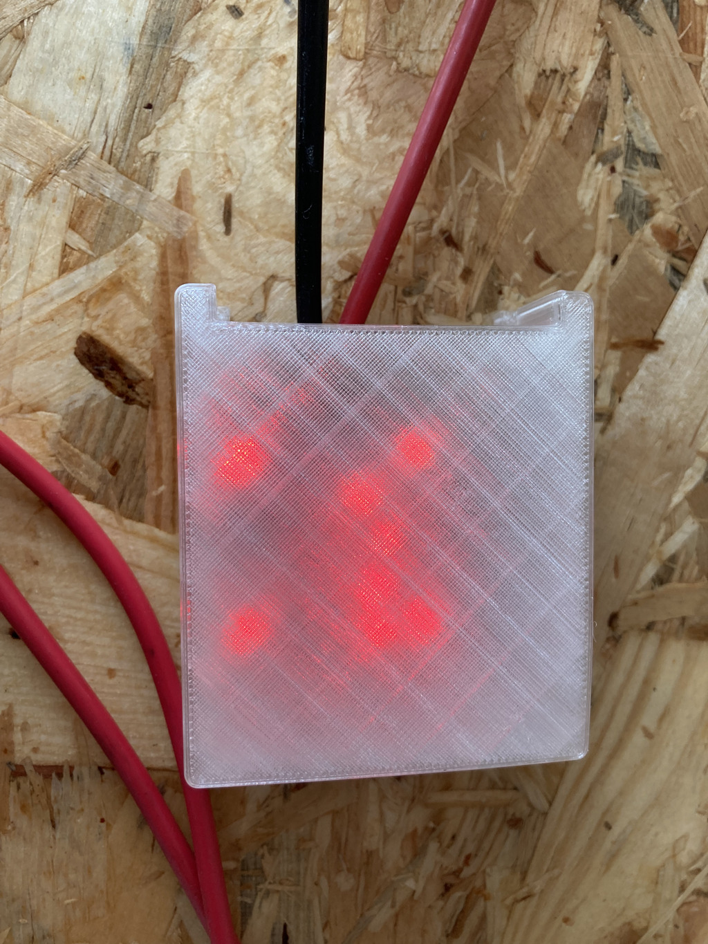
I connected the board to a power supply. The LEDs are visible but the text is very hard to read. I could imagine this technique being used to create a clock.
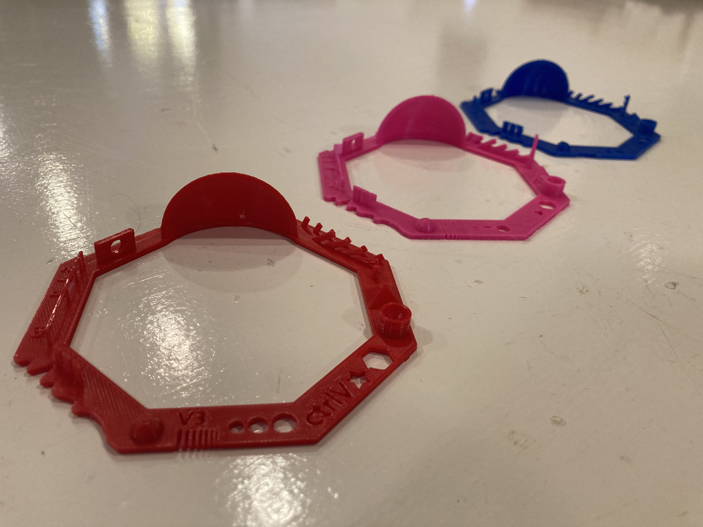
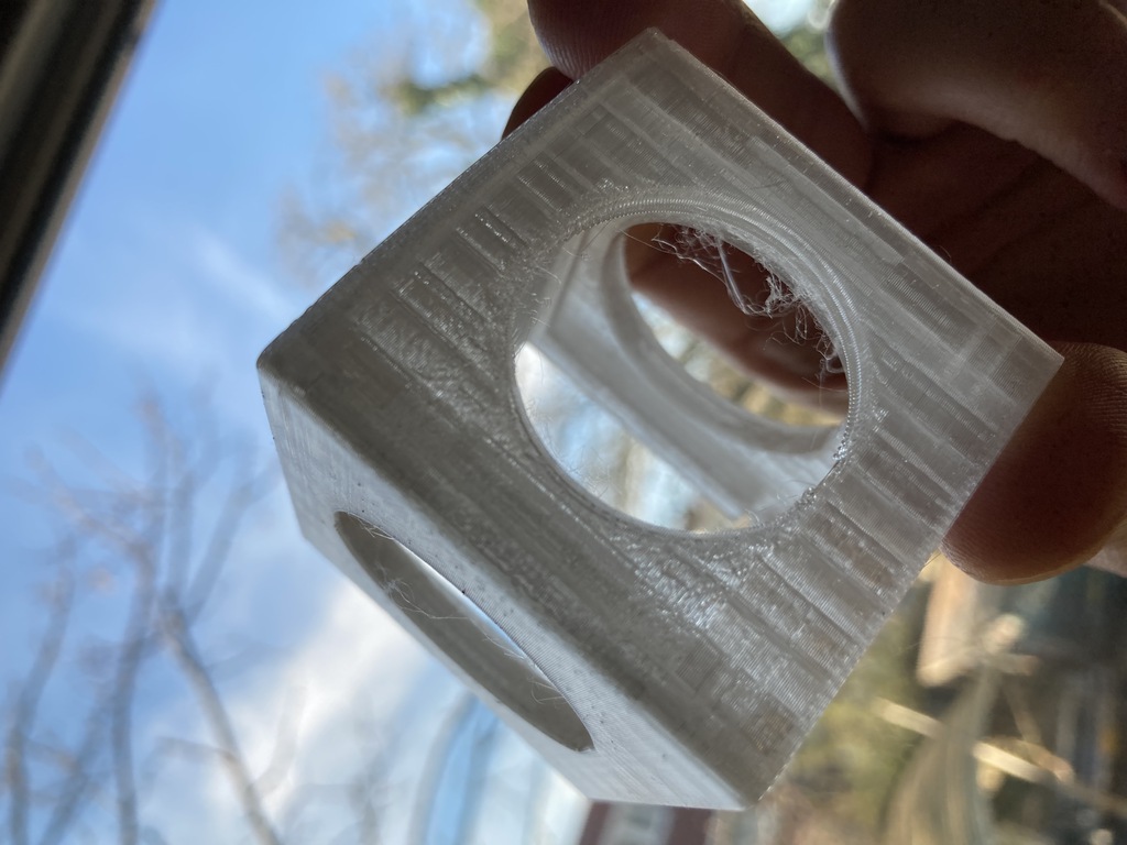
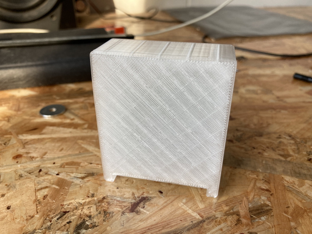
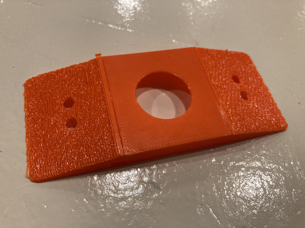
My final objective was to experiment a bit with PETG, as I had not used the material before. The only issue was printer availability. Eventually I was able to start printing version of the case that I designed in week 2 scaled at 40%. My first attempt failed due to too much overhang.
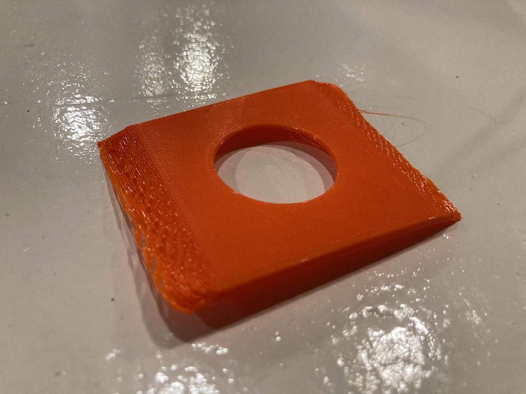
I restarted the print and included supports in Prusaslicer. The printer had some firmware issues, but after a few attempts started printing and the print was succesful. However, the result did not look great, the area where the supports had been attached looked very rough. I wonder if there might be a better orientation, or perhaps better to print the design in parts.
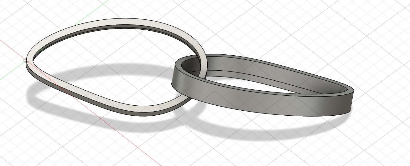
I had one more design left which I was not able to print, but would have been interesting to test flexible materials.
Scan something
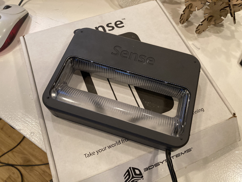
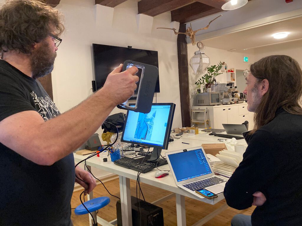
In the Waag we have the 3DSystems Sense Scanner available, which Henk demonstrated to us. There is a dedicated Windows machine which has the software to support the scanning.
For the demonstration, Henk scanned Sander’s head. The process took a long time, but Sander sat very still.
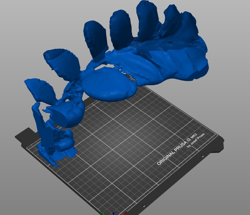
When it was my turn to scan something I chose a fig leaf cutting which in a glass of water. I was hoping the scanner would scan through the glass of water. The scanning was a long and tedious process with a lot of going back and forward because the software had trouble tracking the object.
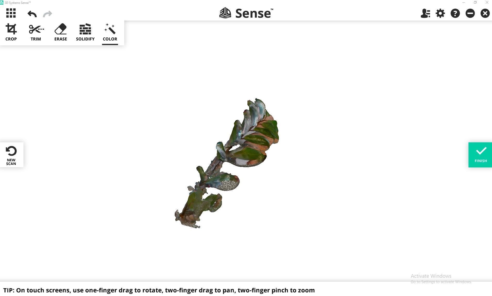
After loading it in Prusaslicer and even before then it was obvious the scanning had not gone great. The model is much more jagged than the plant is.
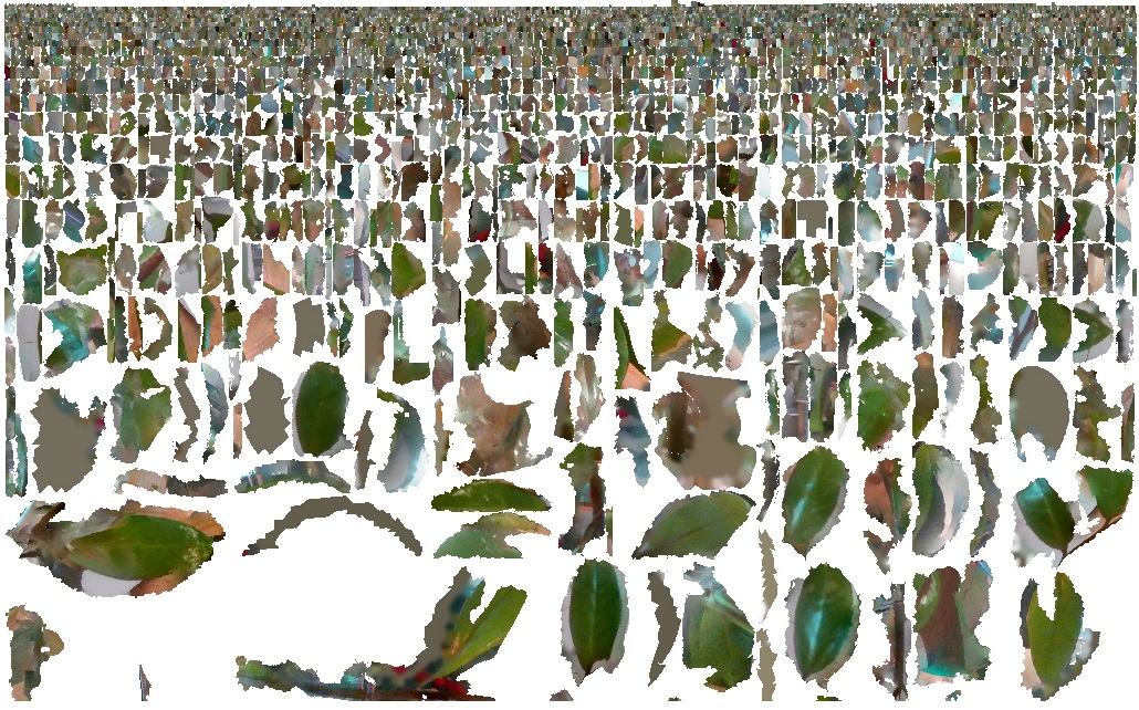
Looking at all the captured images it is easy to see why the model is not very good. A lot of the images have picked up things in the background rather than things that are part of the plant.
Conclusions
- I wasn’t very inspired and found it hard to be creative for the assignment.
- Our Ender 3 should probably be used for PLA only.
- Scanning using your phone probably works better than the one at the Waag.
- 3D printing can be quite wasteful due to throwing away protoypes, it would be nice to experiment with recycling.