Week 2 - Model a possible final project
My notes and comparison of CAD programs is found on this page. During the previous week I already created a very rough 2D sketch of the enclosure of my device using Inkscape. For this week, I will use CAD programs to develop this idea further.
First modeling cycle: basic shape in OpenSCAD
I decided to start modeling my first final project sketch in OpenSCAD. My objective is to create a basic trapezoidal prism which I can adjust by parameters. I found a code example of a similar shape to what I was trying to achieve, however there were some changes to be made to both the model and the way the code was written. The example I found was as follows:
  polyhedron(
  points=[[0,0,0],[17,0,0],[17,17,0],[0,17,0],[1.5,1.5,2],[15.5,1.5,2],[15.5,15.5,2],[1.5,15.5,2]],
  faces =[[0,1,2,3],[0,1,5,4],[1,2,6,5],[2,3,7,6],[3,0,4,7],[4,5,6,7]]);
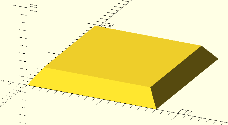
and the model it produced looked as follows:
My approach to changing the code was to firstly make the code parametrized by refactoring the in the vector to be in separate variables.
case_width = 17;
trapezoid_differential = 1.5;
case_length = 10;
case_height = 2;
After some trial and error I arrived at the following easily parametrizable code:
case_width = 40;
trapezoid_differential = 10;
case_length = 10;
case_height = 5;

case_points = [ [0,0,0],
                [case_width,0,0],
                [case_width,case_length,0],
                [0,case_length,0],
                [trapezoid_differential,0,case_height],
                [case_width - trapezoid_differential,0,case_height],
                [case_width - trapezoid_differential,case_length,case_height],
                [trapezoid_differential,case_length,case_height] ];
case_faces = [  [0,1,2,3],
                [0,1,5,4],
                [1,2,6,5],
                [2,3,7,6],
                [3,0,4,7],
                [4,5,6,7] ];

module draw_shape(){
    polyhedron(points = case_points, faces = case_faces);
}

draw_shape();
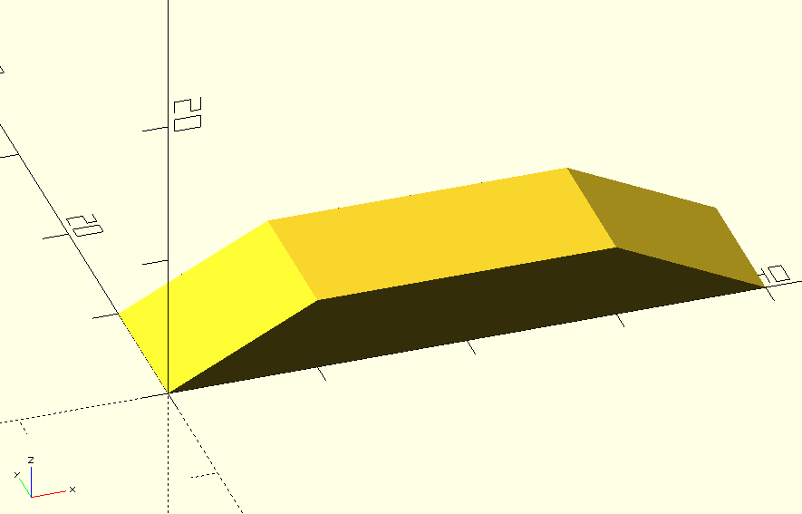
The model that the above code generates is shown below. This is the basic shape I was trying to arrive at, however, of course, it is far from complete. It is now a solid shape, and does not have room for components, ways to be put together et cetera. For the next cycle of my development I wanted to use a graphic CAD tool. I decided that I would first spend working on a more detailed model in Fusion 360 before continuing to test other CAD tools.
Second modeling cycle: shell in Fusion 360
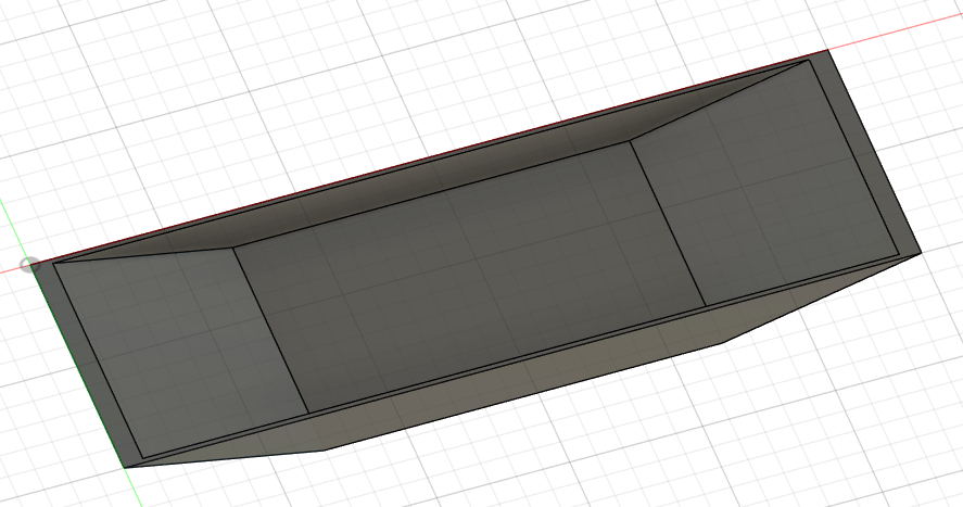
In Fusion, my first thought was to create a similar shape using the lofting tool. I create a rectangle, and another rectangle on a offset plane and then created a loft between them. From the bottom of this solid, I used the shell tool in order to create an outer wall. Now, I needed to create the holes which will allow input and output. However, I wanted to use meaningful dimensions, so I needed to determine what type of input/output devices I would be needing.
Components
- (2) Distance sensors, for now, I will use this ultrasonic sensor (datasheet). It seems parking sensors are generally ultrasonic or electromagnetic. Optical is also an option, but it requires analysis of the images in order to approximate obstacle distance.
- (1) Speaker
- (4) Neodymium magnets
- (6) LEDs
I continued working on the model by filleting the corners of the model, which I did by adding a back to the model. However, I realized that I would need to create the back of the model as a separate body in order to be able to animate them. I had extruded the back of the model by 3mm so I created an ‘Offset plane’ and selected the back of the model and set the offset to -3mm. This worked the way I intended and I was left with a body for the main model, and one for the back model. The next steps would be creating a space in which the inner components would be housed.
Magnets
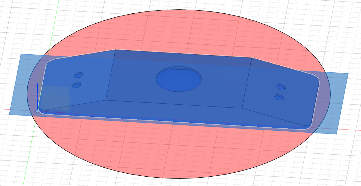
In order for determining the placement of the magnets, I would have to determine their dimensions. For this, I would have to determine how strong they would have to be, which depend on the weight of the device. To estimate this I exported the bodies as .3mf and loaded them in Prusaslicer. At this point I realized that the model I had made was wider than the print plate of a Prusa MK3. I reduced the width of the model by using planes to separate the model into three sections and shorten them.
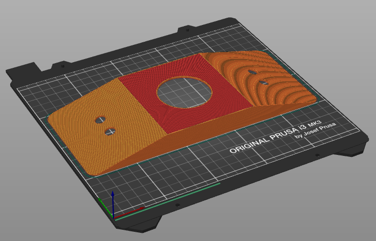
The weight, when printing the model in ABS, was (main part) 55.57 grams + (back cover) 51.2 grams. The weight of a 9V battery is 33.9 grams. I will estimate the additional components, screws, and PCB at 50 grams. For vertical mounting, magnets retain 15% to 20% of their attraction (source in Dutch). Therefore, the amount of magnetic attraction needed is (55.57g + 51.2g + 33.9g + 25g) * (100/15) = 1271.13g, or 317.78g per magnet. These 4x2mm magnets would give us a nice margin of error. Knowing this, I proceeded to model catches for the magnet.
Third modeling cycle: part placement
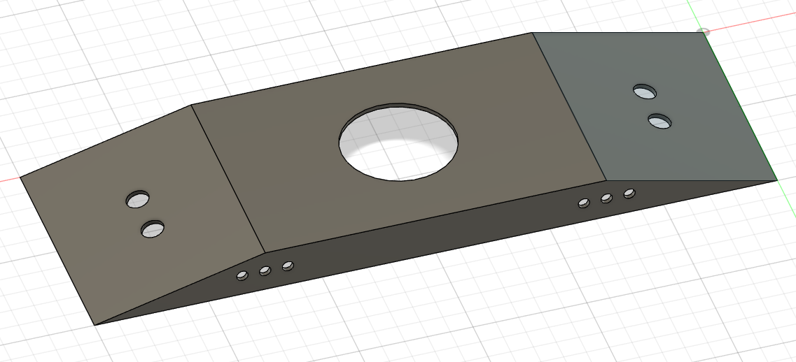
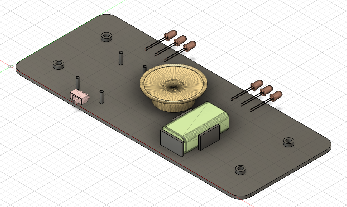
I added four cylinders for the 4x2mm magnets, and also inserted this 9V battery model that I found on the Autodesk gallery. Then, I found a model for a LED on the Autodesk gallery. I downloaded the model, combined the bodies, and imported it as a mesh. Then I moved the mesh to the LED holes and copied it for the other holes. I also added screw holes for the PCB. Then I found this model of a speaker and imported it using the same process.
I noticed the PCB placement was conflicting with the speaker, so I moved the holders for the PCB to accommodate the speaker. The next step is to create place for a switch to turn the device on and off. I was finally able to find a component in the McMaster-Carr directory (I’d searched for all the other components as well but could not find suitable CAD models). The switch I added is the 7395K11_Rocker_Switch. However, at this point it turned out to be way too large. In stead, I had to revert to this switch from the Autodesk Gallery once again.
Fourth modeling cycle: animation
To proceed to creating an animation, I selected all the bodies in Fusion and selected ‘Create components from bodies’. Components are then generated accordingly. I then changed my workbench to ‘Render’ and changed the material for the case to white ABS. I rendered it, and exported as the figure below. It looks a bit funky in my opinion, but I am unsure what to adjust.
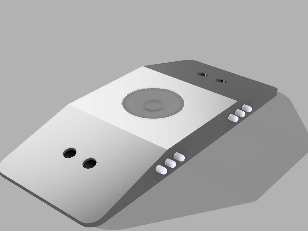
I see now that my rendering isn’t necessary for animation, or that I don’t understand how to use the render. I guess I don’t really understand the benefit of creating a render of just looking at the model in Fusion. Anyway, afterwards, I created a very boring animation that shows the components flying into the case. Now I need to use ffmpeg to compress the video file.
I messed around with ffmpeg and tried to convert the AVI output file. After a while I found the following command on this Stackoverflow page:
ffmpeg -i fusion_animation.avi
  -c:v libx264 -preset slow
  -crf 19 -c:a libvo_aacenc
  -b:a 128k fusion_animation.mp4
The filesize is ~1.3 MB, which should be within the limit.
The f3d model file can be found here.
Lessons
- I’m not sure what the point of rendering, or animation is.
- I don’t know very much about designing cases.
- When working in Fusion, I really should have started by defining parameters. I knew this beforehand, but I thought I could later create the parameters out of the sketches in Fusion. I need to find out how to create a vertex at a certain percentage. Like in the case of a trapezoidal prism where you want the first vertex to be at 1/3 of the total width.