Week 10 - Output Devices
Individual assignment
My code can be found here.
Two-step sequencer FB-101 inspired by the Teenage Engineering Pocket Operator. My idea is to create a new PCB which will be a two step sequencer and drum machine. I wrote some Arduino code which acts like a sequencer. The below code is how I was generating sounds, however I was only able to generate one tone at a time. What I wanted was for three instruments to be able to play at once. I want to define hertz and length for a high-hat, a snare drum, and a bass drum. The Arduino tone() library drives a squarewave using PWM which can be modulated using frequency and length. By tweaking the frequency and length, the squarewave can be made to sound more like the above mentioned instruments. I came up with a basic version of the code using the the tone method from the Arduino library. I used the tx pin from my helloworld board as an output to connect a speaker to and managed to get my code working. So I concluded that my idea could work.
void playInstrument(int in_hz, int in_length) {
  tone(TonePin, in_hz, in_length);              // minimally 31hz
}
I asked about this topic in Mattermost and was referred to the Playtune library. This is a library which support up to three simultaneous sounds on a number of Arduino-based boards. The only problem with it is that it is intended to play a song as in a predefined sequence of notes whereas I want to generate tones ‘on-the-fly’. The codebase of the Playtune library is written in C, so that will also be challenging as I have minimal experience programming in C. Next, I tried to adapt my Arduino code to use the Playtune library. I would need to send bytestreams to the library, and hope that they will also work for short bytestreams.
void Playtune::tune_playscore (const byte *score) {
Also, this is my first test with non-Arduino libraries. On my first try the .ino file cannot find the header file. I will have to put the header file somewhere else. Also I found a similarly named library in the online libraries called Arduboy Playtune. I added the library by Sketch > Include Library > Add .ZIP Library and selecting the Playtune ZIP I had downloaded.
Speakers
Speakers are devices which convert electricity into movement, and the movement is transmitted through fluctuations in air pressure so that they can be heard. A speaker is rated by their impedance which is the nominal resistance they place on the current supplied to it. Typical values are 4Ω, 6Ω, 8Ω or 16Ω. Apart from the impedance, speakers are also rated in Watts. The voltage of a speaker can be calculated by V=IR and the power is calculated by P=VI. Finally, the Root mean square (RMS), a way of indicating average consumption, is calculated by taking the square root of power times resistance SQRT(PR).
A typical speaker can be connected to a circuit by wires, but SMD piezo speakers also exist. It would have probably been nicer to use one of these speakers as the entire project would fit on a board. Especially, when using a button cell. Either way, generally, speakers are connected to an analog-output pin on the microcontroller, and to ground.
Making the PCB
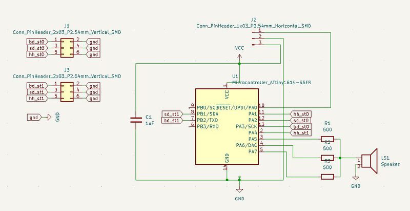
I knew enough about the feasibility of the software part now to proceed with designing the board. I designed the below schematic. I had to remove the serial port as I would be needing six pins for the sequencer configuration and three pins for the output. I started from the helloworld board and worked my way through the design while referring to the datasheet.
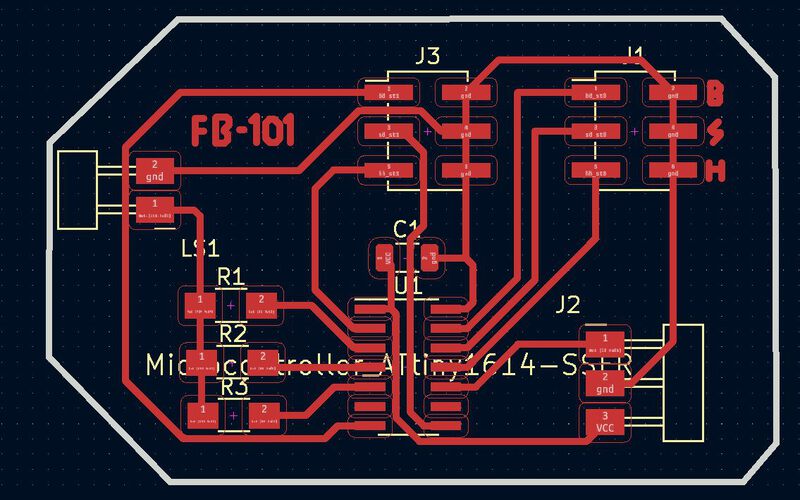
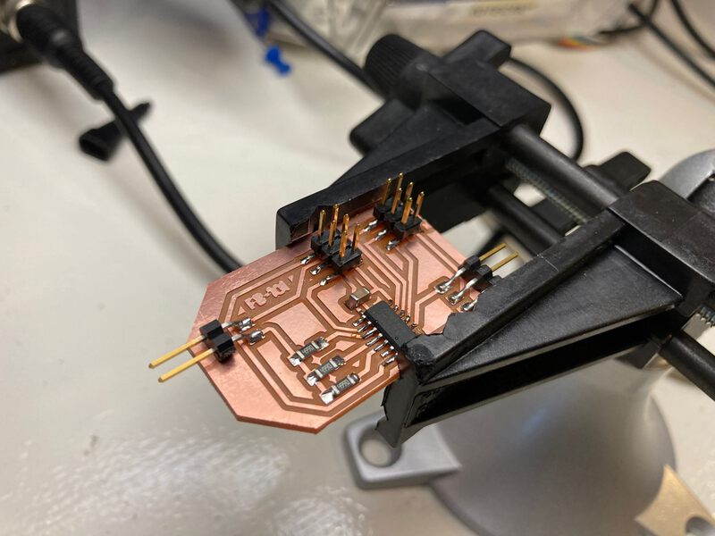
When making the PCB, I made sure to make my traces a little thicker, and especially made my edge cuts thicker. Last time milling on the Modela, I had issues with the edge cuts not showing up in MODS because of their thickness. I had a few issues in MODS but resolved them without losing too much time. After stuffing the board I tested it and I was able to program it right away. A first time for me not making design or soldering mistakes. I was happy even though the board was very simple.
Software development
I had some issues with the jumper pins not properly configuring. They seemed to be randomly having interference causing the configuration to be retrieving HIGH as a value wheareas there was no jumper on those pins. This turned out to be something called floating pins. Luckily, there is a pin mode in the Arduino language called INPUT_PULLUP. So, I was able to solve the floating pin issues with the following two lines. In C I could probably do a nice bitwise operation, but I’ll leave that for another time.
pinMode(bd_st0_conf_pin, INPUT_PULLUP);
seq_conf[0][0] = 1 - digitalRead(bd_st0_conf_pin);
Now to move on to a version of the software that allows polyphony by using the Playtune library. There are multiple version of the library depending on how you intend to use it. Reading the description I am going to start with “Playtune_poll”.
After opening the code in the Arduino IDE, I had to manually include TimerOne library, as it is used by the Playtune code. In the Playtune header the pins are defined for the supported boards, for example:
#ifdef ARDUNIO_MICRO  // define 8 channels on an Arduino Micro
#define CHAN_0_PIN 5    // channel 0 outputs on pin 5,
#define CHAN_0_REG C    // pin 5 is wired to register C,
#define CHAN_0_BIT 6    // and is bit 6 in that register

#define CHAN_1_PIN 6
#define CHAN_1_REG D
#define CHAN_1_BIT 7
et cetera.
So, in this case I could try to define three channels for my ATTiny1614. I created the following configuration:
#ifdef ATTINY_1614  // define 3 channels on a ATTINY_1614
#define CHAN_0_PIN 3
#define CHAN_1_PIN 4
#define CHAN_2_PIN 5
#endif
#define SCOPE_TEST false // make scope measurements?
The problem is the timers for the ATTiny85/ATTiny4313 are different from the ATTiny1614. This causes problems in the below code:
TCCR0A = (1 << WGM01);  // mode 010: CTC
#if CPU_MHZ==16
TCCR0B = 1 << CS00;
TCCR0B = 1 << CS01; // clock select 011: clk/16 prescaling
OCR0A = CPU_MHZ / 8 * POLLTIME_USEC;
#elif CPU_MHZ==8
TCCR0B = 1 << CS01;   // clock select 010: clk/8 prescaling
OCR0A = CPU_MHZ / 8 * POLLTIME_USEC;
#else
unusual frequency
#endif
Sadly, this is where my attempts stranded. I couldn’t figure out from the datasheets how to map the registry names from the ATTiny85 to the ATtiny1614. So, I had to settle for the monophonic version of my code.
Group assignment
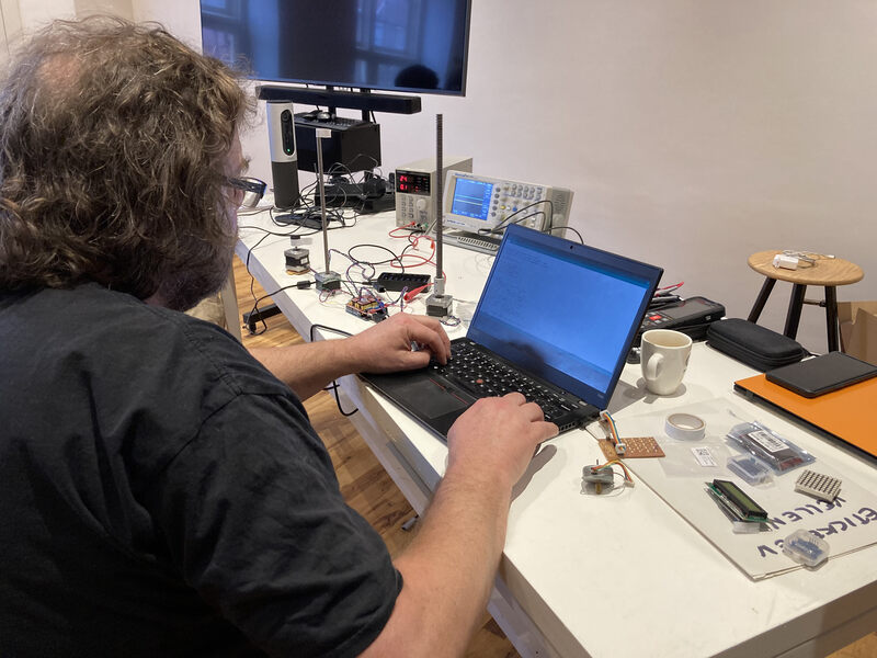
For the group assignment the entire group worked in a single group. Henk showed us the power consumption of different stepper motors and different voltages. He showed us that the difference in current between the resting state and the moving state of the stepper motors was higher at lower voltage levels.
Also Henk showed us that power consumption became higher when you slowed down the stepper motors with your hand. At higher voltages it was more difficult to slow down the stepper motors.
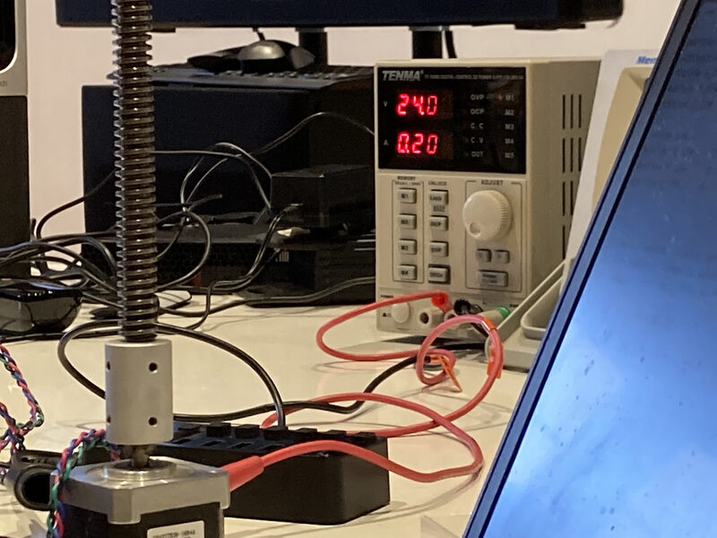
For the next part of the group assignment I worked with Hazal. Erwin had mentioned a method of determining the power consumption of a circuit by attaching a resistor. The formula for the power of a circuit is P=V*I, the current of a circuit is I=P/V, and the voltage is V=P/I. Most importantly, though, is how to calculate the current when you know the voltage and reistance, which is I=V/R.
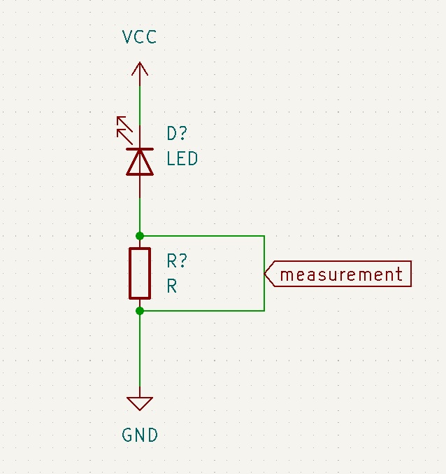
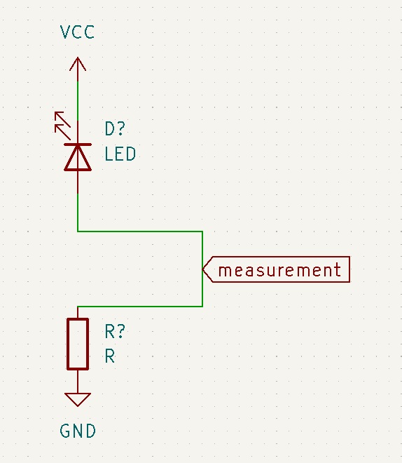
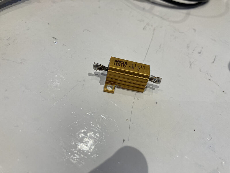
First we had to find a resistor with a large power allowance. The size of a resistor indicates its power allowance. We found a large resistor in the inventory. Googling its part number showed that it had a rating of 15W so that is plenty. The resistance is defined as 1 Ohm. The above diagram shows how to measure the voltage on the left, and the current on the right. The multimeter should be in voltage mode for both measurements.
We tried to put the resistor in parallel to the circuit using a power supply and a multimeter in voltage mode, but had some problems getting an accurate measurement, so finally we abandoned the idea and used the multimeter directly.
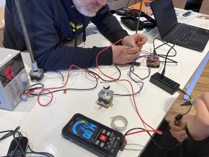
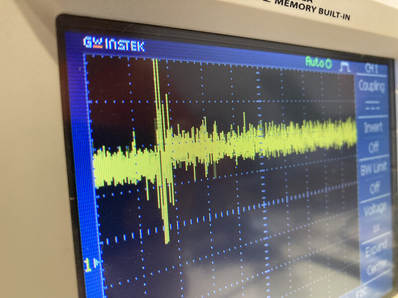
Finally, we used a oscilloscope to measure the power consumption. It took us a bit of time to find the correct time and amplitude resolution. Eventually, we managed to get a good measurement.
Conclusions
- I had a difficult time understand the interaction between .ino, .c/cpp, and h. files while working in the Arduino IDE. It seems like there is no difference between adding a file as a library and opening it in another tab. Also verifying a file will automatically verify all files.
- You need a lot of knowledge of the board you are adapting a library for, as well as the library you are coming from. It takes a long time digging around in datasheets before you know what a value is being used for.
- It would be nice to add an SMD piezo speaker, button cell, and potmeter to determine BPM.