Week 8 - Embedded Programming
This week’s topic is embedded programming, which is the most important. We will see if the boards we have been preparing for the past weeks will work. In my case the answer will be ‘no’. Generally, this week was about getting code to run on our circuit boards. The easiest way to do this is using the Arduino language and architecture. Alternatives are C/C++ and Python. Erwin showed us some of the C he had written for his projects and it looked very complex to me. For instance, using bitwise operations on memory registers. Although I’m comfortable programming, this seems to complex for the moment. There are many alternative IDEs and architectures to use.
Different types and uses of memory on an integrated circuit boards
- SRAM (quick volatile storage)
- DRAM (big volatile storage)
- EEPROM (registry and non-volatile storage)
- FLASH (programs and writeable storage)
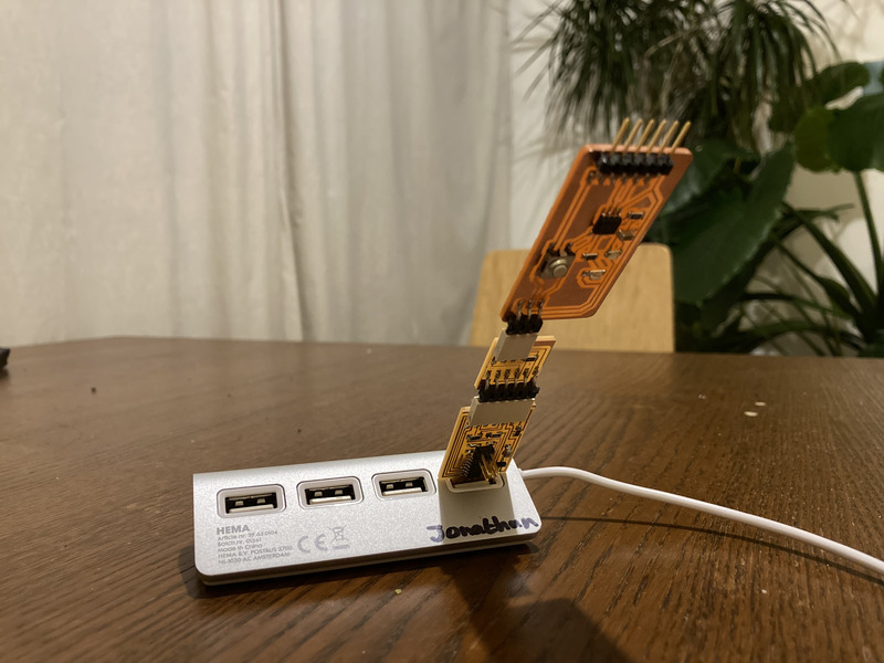
An important concept for me was to understand that when you connect three boards together, in my case the SAMD11CA configured as serial -> 3-pin UDPI adapter -> helloworld with ATTiny 412 act as a single board in a way. By this I mean that if you compile a sketch in Arduino and upload to this sequence of boards, it will only be written to the flash of the ATTiny.
Make sure to add these URLs to your board manager in the Arduino IDE:
https://raw.githubusercontent.com/qbolsee/ArduinoCore-fab-sam/master/json/package_Fab_SAM_index.json
http://drazzy.com/package_drazzy.com_index.json
https://www.mattairtech.com/software/arduino/package_MattairTech_index.json
Then go to ‘manage libraries’ and install the following libraries: - megaTinyCore - Arduino AVR Boards - Fab SAM core for Arduino - MattairTech SAM D|L|C…
Reading a datasheet
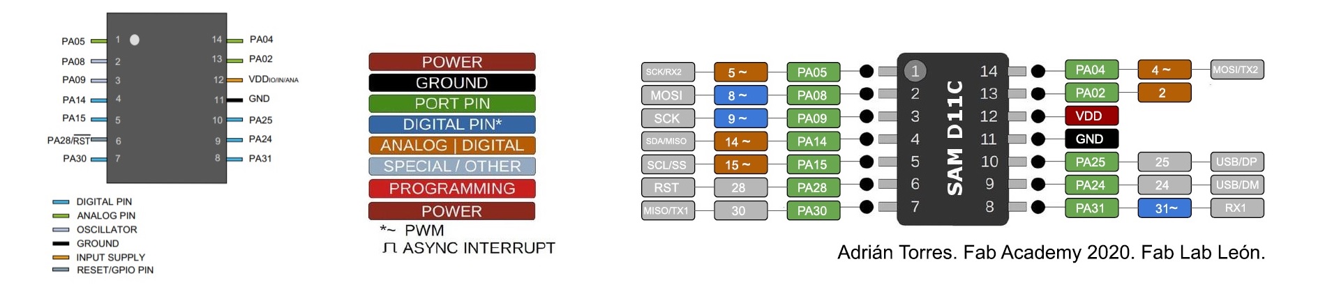
For this week’s assignment I went through the datasheet for the SAMD11C. The most important takeaways from reading the datasheet were:
- The location of the TX1,2 and RX1,2 pins are PA30 and PA31 for TX/RX1 PA4 and PA5 for TX/RX2.
- The MISO/MOSI pins for SPI are PA30 and PA8.
- The SDA/SCL pins for I2C are PA14 and PA15.
- The VDD/GND pins are 12 and 11.
- The reset pin is PA28.
- The operating voltage (~3.3V).
An illustration that I found very useful, but was not in the datasheet, but rather hosted on the page of Adrian Torres, was the (extended) pinout for the SAMD11C.
Individual assignment
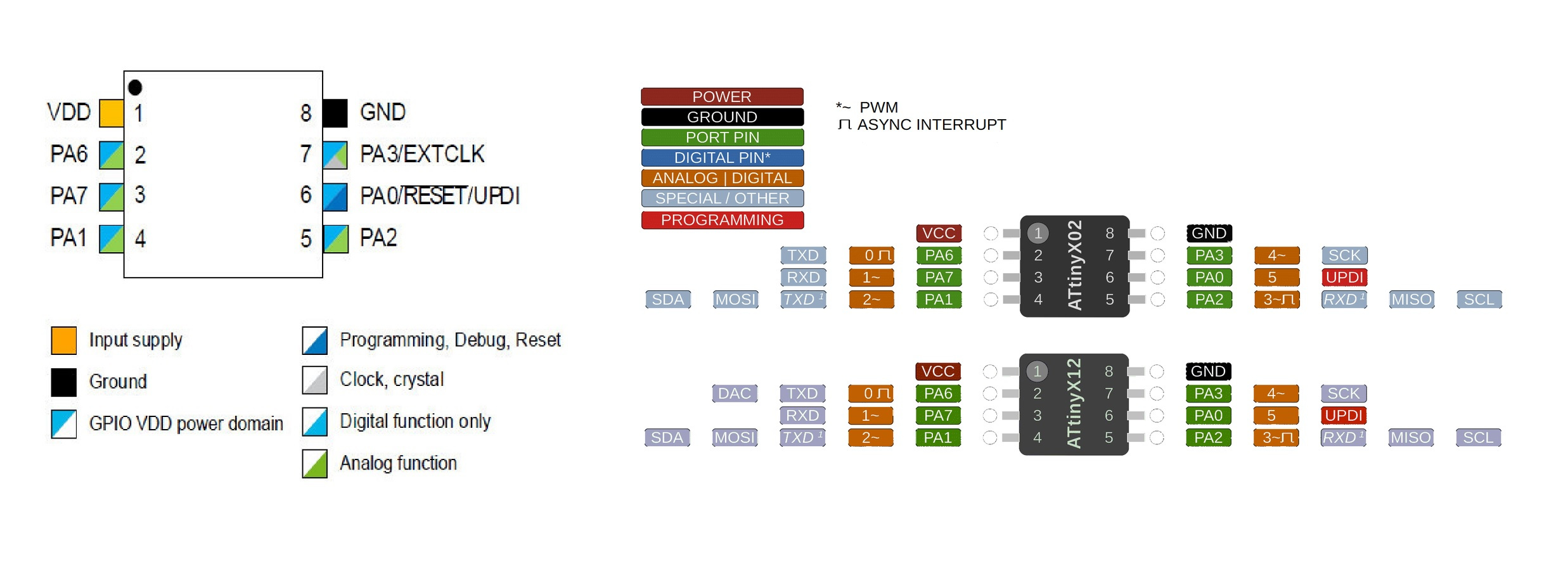
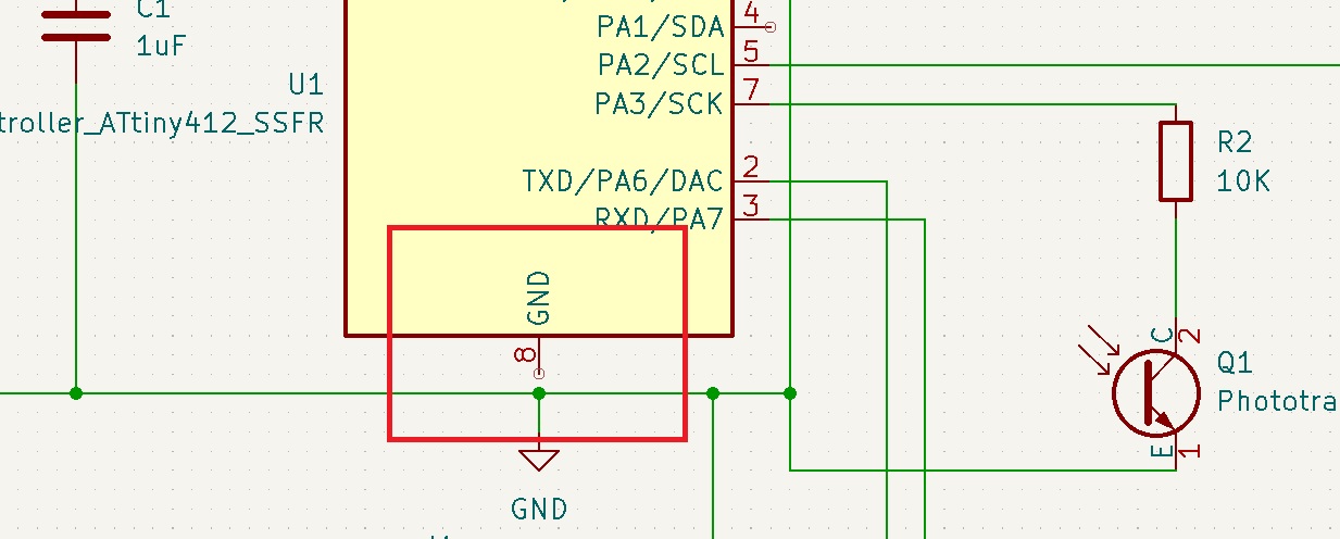
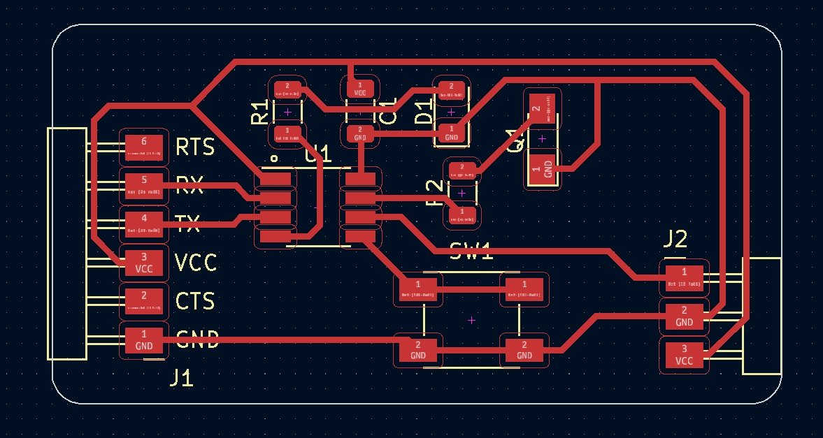
The problems started on Thursday when I tried to upload a sketch to my hello world board which uses an ATTiny412(Datasheet). I connected the pins in the following way. The TX/RX pins had to be connected to the serial connector. In the case of TX/RX connections, the TX pin of the ATTiny412 (PA6) should go to the RX pin of the connector, and the RX pin (PA7) goes to the TX of the connector. I connected the Phototransistor to PA3 with a 10K resistor in front of it. PA3 supports both digital and analog reading and writing, but analog is needed for the phototransistor. The button or switch went onto PA2. PA0 is used for the UDPI connector to enable UART programming. Initially, I had attached my LED to VCC to see if the board was powered, but I later moved it to PA1.
Design mistakes:
- In my schematic I had neglected to completely connect one of the wires leading to the ground. The missing wire (almost) went from the IC to the ground. Because the schematic was wrong, the PCB validator did not show an error. As a workaround, I added a jumpover cable from a ground lead.
- The order of my UDPI pins was not correct
- For an unknown reason, possibly my settings in MODS, some of my traces were very thin
- I had thought it would be good to connect my LED from VCC to ground so that it could be used to see if the board is being powered. However, that also means that I cannot use my LED to give any feedback.
Other mistakes:
- Unable to program.
- Occasional smoke due to I think leftover flux.
- Confused by mixed usage of firmware and bootloader.
- Wrong bootloader on programmer board.
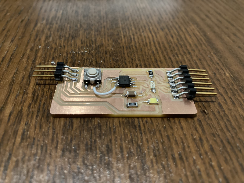
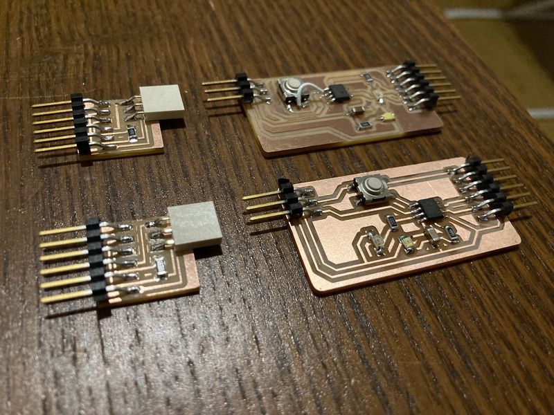
After testing a little more with Henk, I decided to remake the 3-pin UPDI to FTDI board, as well as correct the mistakes in my design. I also ran into many problems while milling new versions of my board. Which I’ve added below.
Milling issues:
- Outline (as SVG) is too thin to be picked up, the resolution was to decrease tool size to 0.1mm. This may cause exterior traces to be milled off.
- Traces and pads were disconnected during milling, the resolution was to increase the DPI to 1000 from 100. For some reason the default was 100.
- When using PNG, MODS crashes when you try to invert or rotate.
Finally, I was able to program a simple program on my board using Paola’s FTDI 230x board. Unfortunately, I was not able to program it using my own programmer as it had also developed issues. I would have to solve those issues later, but in the meantime I was able to write the code below to my hello world board. The code checks to see if the phototransistors output is above a certain threshold and then turns on the LED.
int threshold = 60;

void setup() {
  pinMode(PIN_PA3, INPUT); // phototransistor
  pinMode(PIN_A1, OUTPUT); // led
  Serial.begin(9600);
}

void loop() {
  Serial.println(analogRead(PIN_PA3));
  delay(500);
  if(analogRead(PIN_PA3) > threshold) {
    analogWrite(PIN_A1, 200);
  } else {
    analogWrite(PIN_A1, 0);
  }
}
The next day I started looking at why I wasn’t able to program using my programmer. After resoldering and checking some leads I realised I had written the wrong bootloader to the SAMD11C while debugging last week. After writing the correct bootloader and the serial program to the SAMD board, I tried to program my helloworld board again.
xPSR: 0x01000000 pc: 0x000004a0 msp: 0x20000ffc
target halted due to debug-request, current mode: Thread
xPSR: 0x01000000 pc: 0x000004a0 msp: 0x20000ffc
** Programming Started **
Info : SAMD MCU: SAMD11C14A (16KB Flash, 4KB RAM)
** Programming Finished **
** Verify Started **
** Verified OK **
shutdown command invoked
Info : Listening on port 6666 for tcl connections
Info : Listening on port 4444 for telnet connections
After a few attempts I was succesful. I debugged the above code a little and tweaker the threshold and finally it worked. The LED lit up after covering the phototransistor.
I expanded the code a little bit so that the board can exist in two states. One where the LED blinks and one where the led lights up if the phototransistor is covered. The state is switched using the button. It was interesting to try this, but there is probably little need for code which has multiple function states. It is probably a better practise to write dedicated code and only upload that which is needed.
static int threshold = 60;
static int status;

void setup() {
  pinMode(PIN_PA3, INPUT); // phototransistor
  pinMode(PIN_A1, OUTPUT); // led
  pinMode(PIN_PA2, INPUT); // button
  Serial.begin(9600);
  status = 0;
}

void loop() {
  Serial.println(digitalRead(PIN_PA2));
  if(digitalRead(PIN_PA2) == 0){
    delay(500);
    switchState();
  } else {
    if(status == 0){ //photo_led_state
      delay(200);
      if(analogRead(PIN_PA3) > threshold) {
        analogWrite(PIN_A1, 200);
      } else {
        analogWrite(PIN_A1, 0);
      }
    } else { //blink_led_state
      analogWrite(PIN_A1, 200);
      delay(100);
      analogWrite(PIN_A1, 0);
      delay(100);
    }
  }
}

void switchState() {
  status = (status + 1) % 2;
}
Conclusions
- I realized I will probably have to remake my SWD Programmer board as well. Meaning that basically all the boards I’ve made during the electronics production week had problems. I think the boards I am making now are better, but I need to substantially improve the quality of my boards if I ever want to use them in a functional project.
- My debugging process is not great, I have a hard time narrowing down where my issue is. Especially the bootloader issue confused me a lot.
- I spent the entire group assignment time debugging my board, during which time I could have probably better been comparing workflows.
- I would like to know more about the communication protocol when uploading sketches or other code to the boards.
- I am really unsure of which board to use for my final project. Apart from native USB, I’m not seeing any difference in the SAMD11C and the ATTiny412.