Week 7 - Make something big
Introduction to the machine
Unfortunately, due to Coronavirus, I wasn’t able to attend the introduction in person. I tried to follow along via Zoom. First, Henk went over the safety precautions of the machine. Notice where the exits are. Main door and emergency exit. Notice where the fire extinguisher is, one in this space one in the next.
Electronics of the machine are back at the end of the machine in a closet at the end of the room. That is where you can turn off all power to the machine. On the machine you don’t want to touch, the stop button. Only on emergency. You have to recalibrate, load design files again. The ‘bridge’ contains the z-axis and the ‘arm’ contains the y-axis. Along the machine towards the end of the room is the x-axis. Z-axis works with a rather big stepper motor. The speed of the spind is 18,000 rpm. There is a stepper motor on both sides. The teeth of the steppers use the teeth on the bottom with a rail. Do not touch the machine while operating. Servicing is done using a 2-inch flute.
The teeth on the wheels are rather sharp. All moving parts on this machine are dangerous. Before starting the surroundings of the machine are clean. Nothing on the sacrificial layer. Nothing leaning against the machine. You shouldn’t mill the sacrifial layer (mdf). Henk serviced the sacrificial layer and made sure there are no woodies. If you see a spark, turn off the machine, turn off the suction, go to the bag stick your head in. Smell for fire. The black wrench is used to change the spindle, it is attached to the key, so you cannot adjust the spindle without removing the key. Henk starts the software and gives an error because the machine is not on.
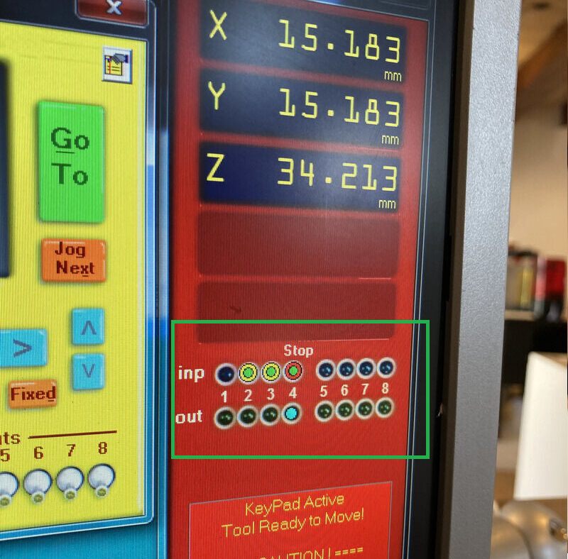
Don’t use the mouse, use the keypad to move it around. To level z-axis, press k for keypad and navigate to middle of plate and level the z-axis. Don’t push the machine to the limits of the machine using the keypad. Take a picture of your job home in case you turn off the machine.
Start machine before starting the software. Milling bit, collet, nut. The order is: 1. Collet 2. Milling bit 3. Nut.
5mm bit goes in a 5mm collette. Put in the parts one by one. Wingnut on the back of the head that holds the vacuum tube. Collet into the nut, then the end mill (tool). It needs to stick out enough to do the job. It should stick out at least the material thickness. And it needs to be in far enough to be connected to ???. Tight enough for the machine to hold the tool, loose enough that the next person can remove it again.
Creating toolpaths in VCarve Pro
- Create a new file.
- Measure the thickness of your material at different places and average, and set it in Material(Z) Thickness. Z Zero indicates where you will zero, in the sac. layer or on top of the material.
- Job Size (X & Y) are the dimensions of the the entire board.
- XY Datum Position will be bottom left.
- Modelling resolution (Standard (fastest)).
- Create a pocket (e.g.).
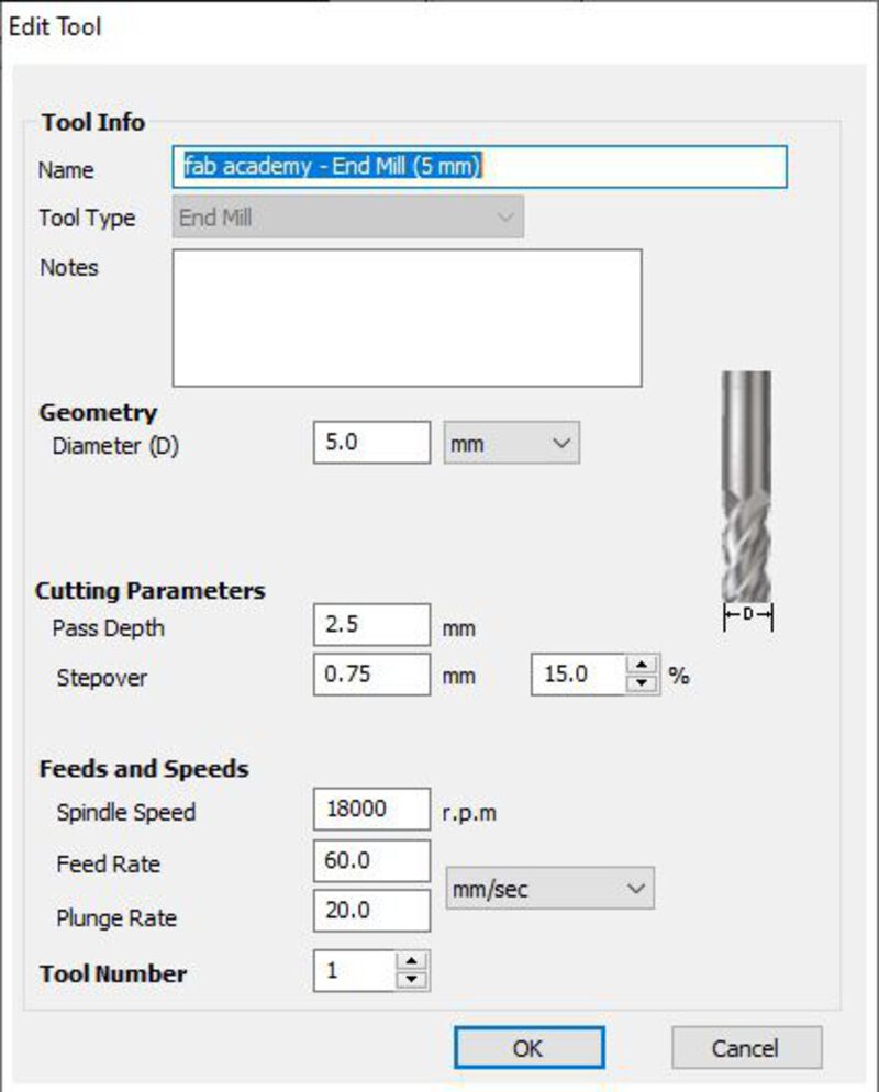
- Tool database add new end mill 5mm
- Pass depth should not be more than half of your end mill.
- Pass depth is how many mms per pass, ‘max depth’ on the Roland is ‘Cut Depth (C)’ on this machine.
- Stepover 0.75mm (example) / 15%
- Spindle Speed 18000 rpm
- Feed Rate 60 mm/s (how fast it travels)
- Plunge Rate 20 mm/s
- Tool Number: 1 for 1 tool.
- Clear pocket leave at climb.
- Select vector and you will get a preview.
- Ignore kerf and solve by using inside/outside jobs.
- Do separate last pass to remove as many woodchips as possible.
- Add tabs to toolpath will add tabs with custom sizes. Tabs in the corner are easier to saw off.
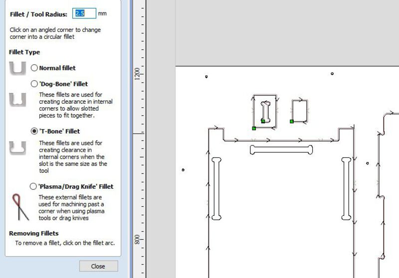
- For inside corners you need fillets, but outside corner can be straight.
- Outline profile toolpath
- Add screws where you will add screws size of milling bit.
- Select all the screws, add toolpath, add drilling toolpath with cut depth of 1mm.
- Preview all toolpaths check if it looks good and save it.
Individual assignment
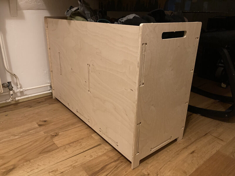
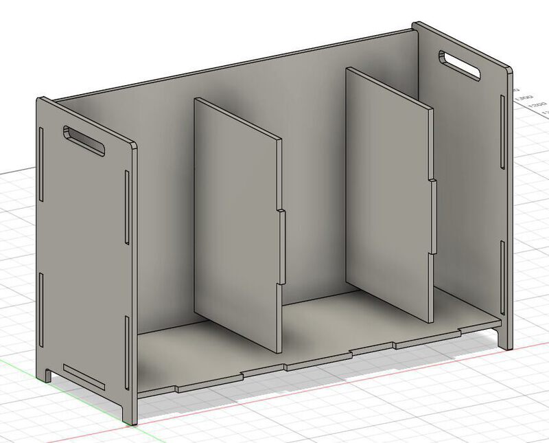
The assignment was to design something big. I designed a laundry basket for my house that would fit exactly under our sink in the bathroom. I used Fusion 360 to design the laundry basket. It is a pretty simple box with filleted corners.
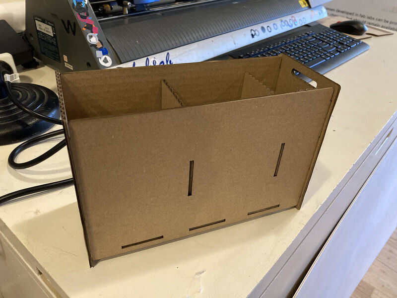
I tested the pressfitness of the design by lasercutting a scale model of the design using our lasercutter. I set the kerf at 0.27mm using DXF for laser, but the fit was a little too loose. Regardless of the fit, the overall design seemed to fit well and looked as expected. An interesting note on the creation of the maquette was that the material I selected for the assignment was 12mm and there was plenty of cardboard left at 3mm so I only had to scale the mode in Fusion by 25% without adjusting the material_thickness user parameter I had used in the model. It seems like things are easier when your intented maquette is a conventient factor smaller than the full-size target material.
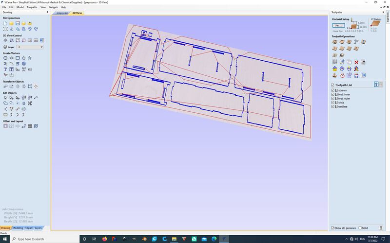
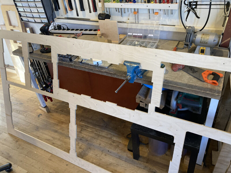
So on Monday I went the workspace to prepare my file for the shopbot the day after. I had two open vectors which I fixed easily using the tool in VCarve. I added T-bones to my slots because dogbones were overlapping because they were too close to oneanother. I oriented them in a way so that they ‘just’ fight.
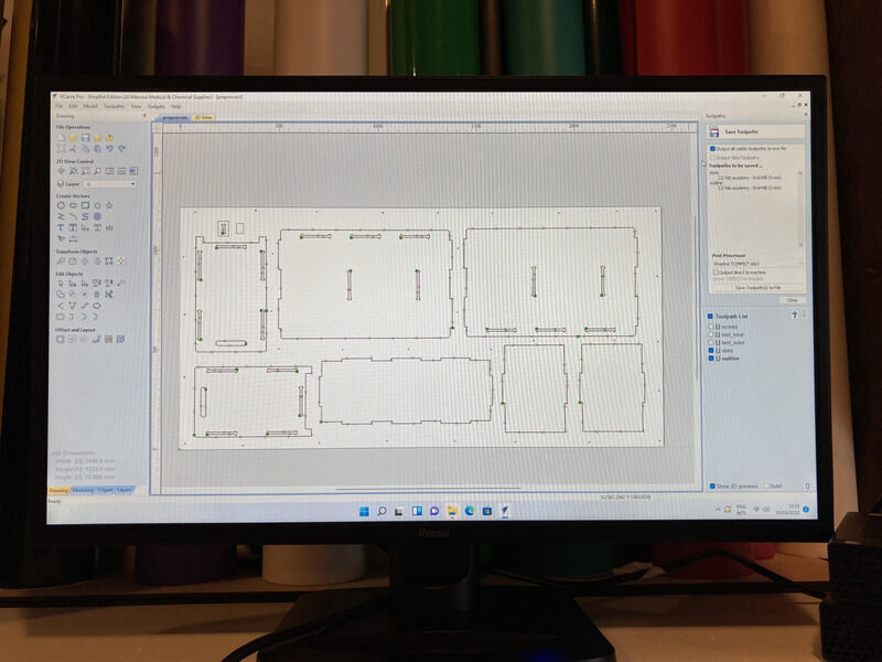
After recalculating some toolpaths and adding screws which I had forgotten to do earlier, we were ready to work with the machine. I also added a slot to test the tolerances and had five toolpaths in total (screws, inner test, outer test, inner parts, outer parts).
I decided to use a 5mm endmill, hoping that this would give me enough definition on the cuts without taking too long. After importing the DXF files from Fusion 360, I added T-bones using the T-bones tool in VCarve Pro. Their size was automatically determined based on the size of the tool to be half of the tool diameter. The ‘Dog-Bone’ and ‘T-Bone’ tools are found under ‘Create Fillets’.
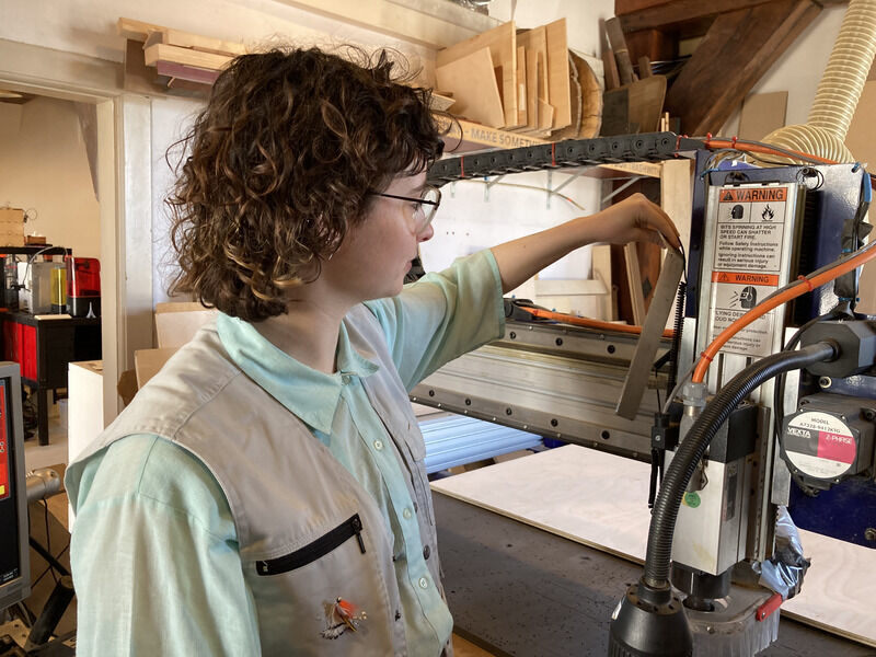
Having generated the toolpaths and being satisfied with the settings, I moved on to the Shopbot. The machine uses a piece of metal to automatically calibrate the z-axis. The metal part is placed on the MDF sacrificial layer beneath the mill on a representative location and the machine does the rest.
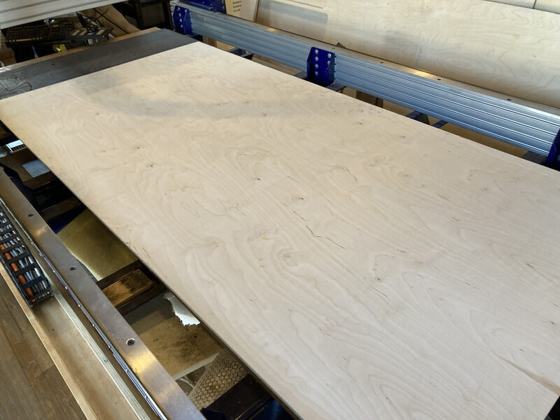
The next step was to get my piece of 12mm plywood. I had measured the plywood in multiple places and came to an average of 12.085mm. I adjusted for this in VCarve. After getting the plywood we places it on the bed.
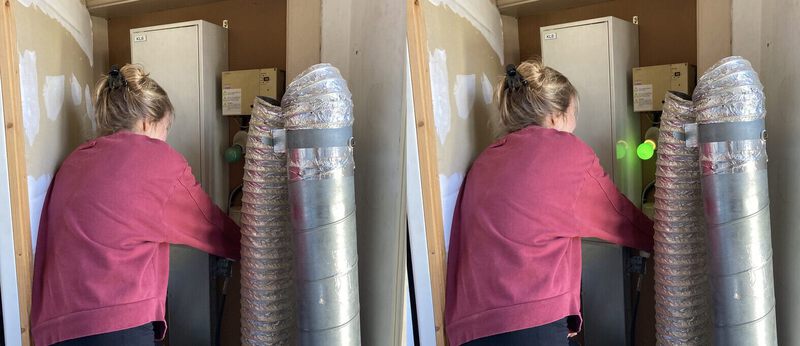
Now we were ready to mill, so we switched on the power to the ventilation system.
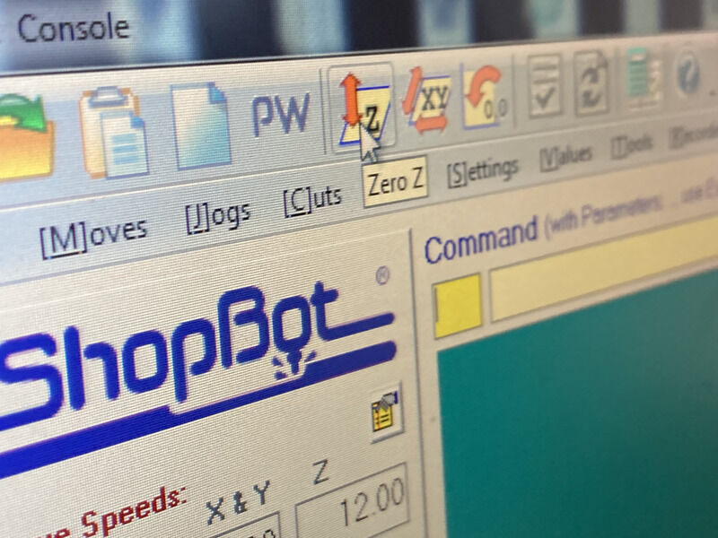
After milling the first drill hole the mil dragged the entire plywood sheet, so we quickly stopped the job. The corner of sheet was lifted a little above the sacrifial layer due to the wood being a bit warped, and perhaps due to a bulge on the MDF layer. However, upon rechecking my preprocessed file, it turned out I had selected the wrong z-level location in VCarve. So we had to go back and recalculate my layers.
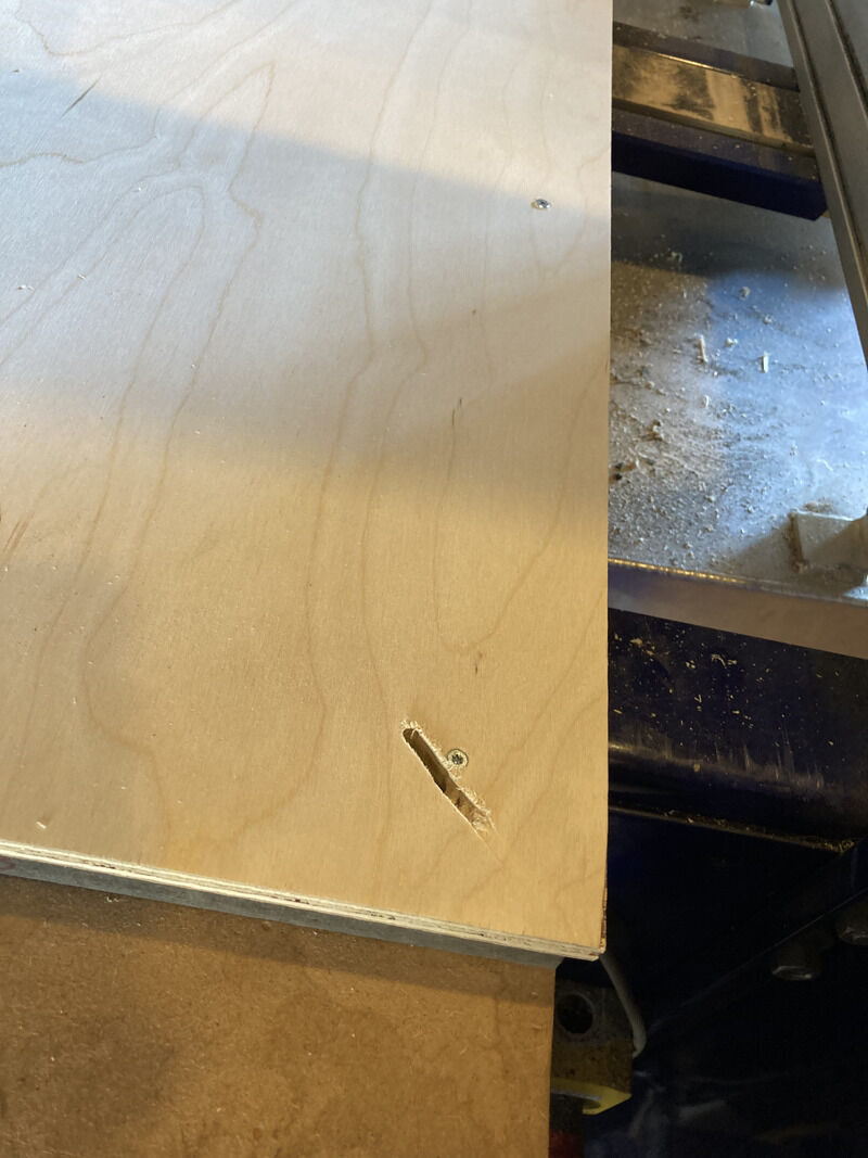
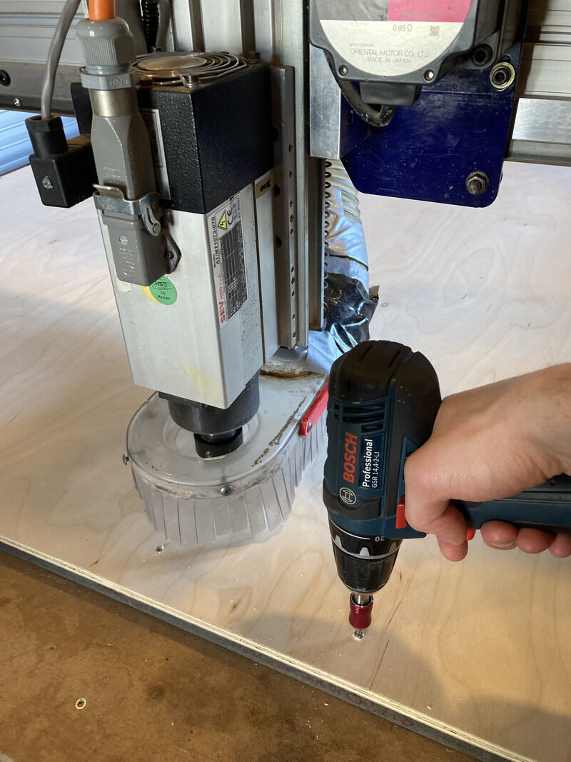
After fixing this issue, the drilling of the screwholes proceeded without incident and afterwards I screwed in 33 woodies into the sheet. Michelle made me count them so that I would remember afterwards how many to take out.
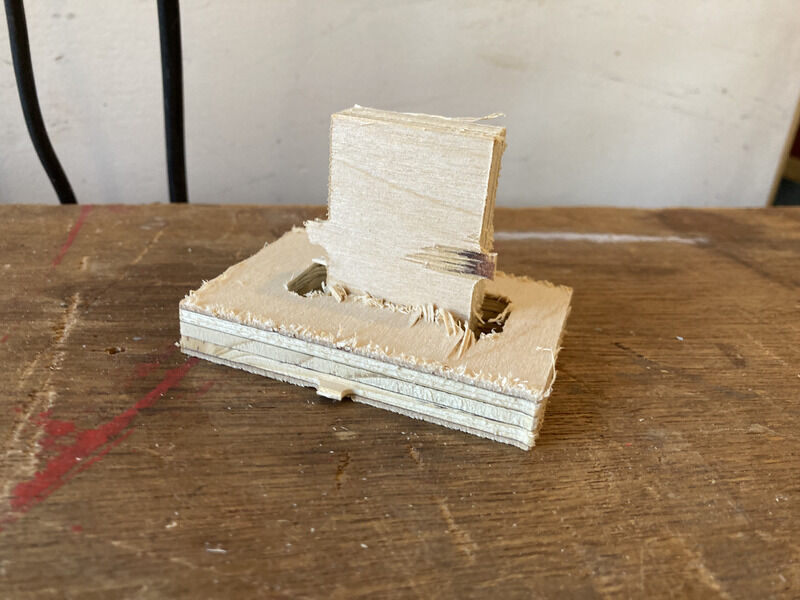
The next test was to test the tolerances of the materials. For this we had prepared a small rectangle and a rectangle with a slot in it. Although the cut was very rough the material fit well sideways.
So with that result, there were no further adjustments necessary and it was time to start the main job of milling the inner and outer lines. The milling went smooth overall, however some of the slots had some thing residue of the wood that had been in the center. Sometimes they were sucked up into the ventilation, but sometimes the got briefly stuck in the area around the mill. Which could be scary as it could cause a fire if exposes to the mill for a longer period.
So finally, after removing 33 screws, we were able to remove the plywood and replace it with the plywood that Joany was going to use. In the meantime I would be able to start removing my panels by carefully removing the tabs.
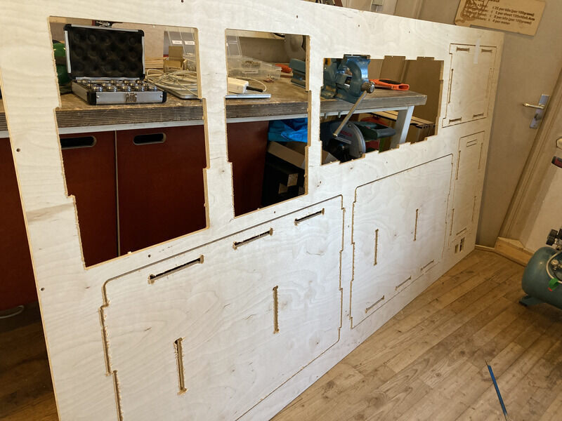
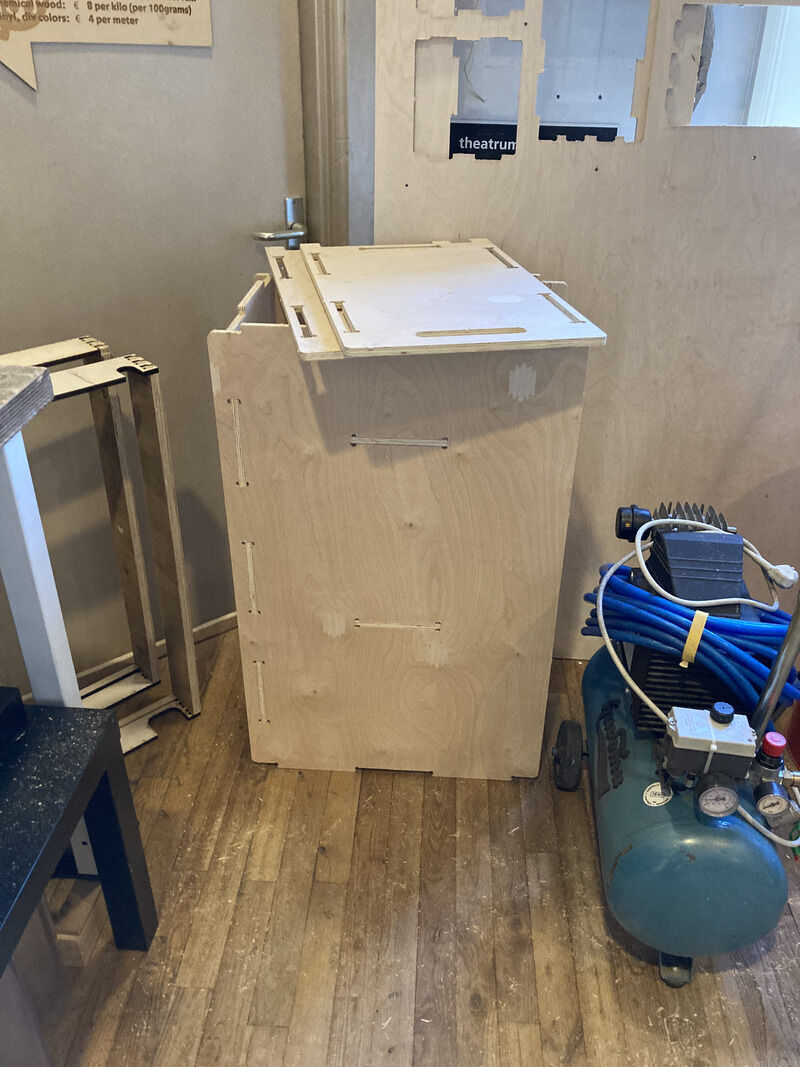
So finally, I was left with my part pieces. My first steps where to cleane the edges with a file as it was quite rough wherever it had cut against the grain. I also did a bit of sanding of the slots and tabs. I started to but a few pieces togeter, hover after having most of them fit nicely, the side panels dit not turn out to fit that well. The maquette showed that the design shoud work in principle, how using cardboard allows tolerances to be streched. I will try to bring the pieces home in the next days and sand them some more and after that combine the pieces and postpress.
Hopefully soon there will be a better hero shot but for now:
Conclusions
I made few mistakes, the most dangerous one being not choosing the correct bed-levelling. If I had been aware of how this was datermined it would have been easy to prevent. I was very lucky with my test slot fitting on the first try. It would have taken ages to back to my model, chane the material_thicknes variable and then open it again in VCarve and start all over again. This week my time was extremely limited due to illness, and honestly quite happy that I got as far I was able to.
Here is the original design file.