Week 4 - Electronics Production
Notes
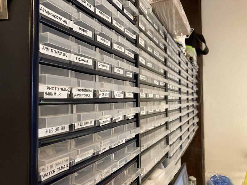
FTDI - talks serial with mc and has seven pins(?) UPDI - can program mc and has four pins SWD-board has onboard/native USB. Etching consumes a lot of water and uses hazardous materials. For 1-10 pieces it is fine to use milling. For larger numbers the boards can be sent to ‘board houses’. Setscrew holds the head of spindle. Kline vs. conventional machining 0 ohm resistor can be used to hop over traces (1.5D board). Make sure you make a comb. Wash with soap and water BEFORE stuffing with components. clean with IPA after stuffing (get rid of flux residue). The 0.8mm mill is on a magnet in the middle of the mill.
FR1 is what is generally used in CNC machines, FR4 is used in board houses, but is unsafe to mill in.
Roland Modela MDX-20 CNC
- Turn on the mill
- Start mods with
bash mods - Check that the mill head is in the raised position.
- Remove and insert the drill bit that you want to use.
- Turn on mods after starting the machine.
- Load your SVG or PNG.
- Check settings, make sure that your cut depth is not larger than the bit width / 2.
- Move the drill bit to the origin, and try to find your starting point. Remember the coordinates.
- Optionally, you can calibrate the mill height at different point on the plate and move back to the starting coordinates.
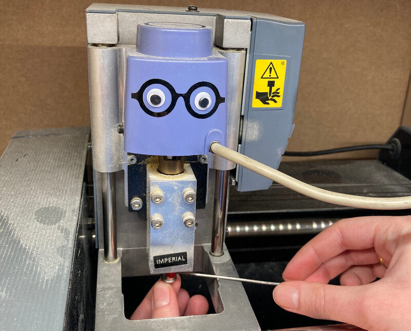
- Carefully lower the milling bit and use your finger to stabilise the bit while tightening.
Open port if it isn’t open after starting mods first. If any error in the terminal restart the process. When using SVGs make sure to set the DPI to 1000 and of course invert if necessary.
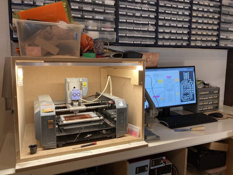
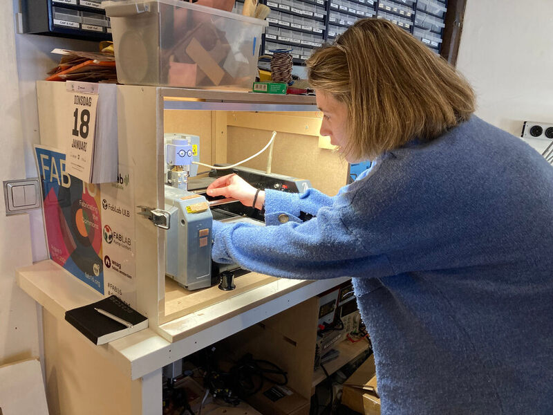
We started the day with Henk showing us how to attach a new copper plate to mill. The baseplate for the CNC mill consists of two layers of acrylic, one layer of sacrificial copper plate, and finally the copper plate that is intended to be milled. The top plate is attached to the sacrificial plate using six strips of two-sided scotch tape, which is located in the milling enclosure.
The CNC is controlled by a PC which to the right of the enclosure. Using mods you can send PNG or SVG files to the printer. There is also a box of drill bits inside the enclosure to the right of the printer. Inside are a 0.39mm 1 flute, an ‘old’ bit, and a 0.39mm 2 flute drill bit. To
For the first layer, Henk changed settings in the ‘mill raster 2D’ after loading a PNG. Instead of 0.04 inch cut depth and max depth, he set 0.02. Which is 0.0508 in mm.
After inserting the 0.39mm tracer bit, he lowered the head to approximately 1cm above the copper plate. First he moved the milling bit to the origin, and remembered the coordinates by looking in mods. Then, he moved the head to 30x30y to calibrate at a more representative point i.e. not at the edge of the plate.
He then milled the traces using the old bit. Afterwards, he changed the bit to the 0.8mm one and milled the outline.
Group assignment
TODO: Add limit, mention the comb is in inches. TODO: Document the ‘batch’ milling process.
“Characterize the design rules for your in-house PCB production process: document feeds, speeds, plunge rate, depth of cut (traces and outline) and tooling. Document your work (in a group or individually). Document your work to the group work page and reflect on your individual page what you learned.”
We started the group assignment during which I worked with Paola, Sander, and Ben. The assignment was to characterize the design rules for your in-house PCB production process: document feeds, speeds, plunge rate, depth of cut (traces and outline) and tooling.
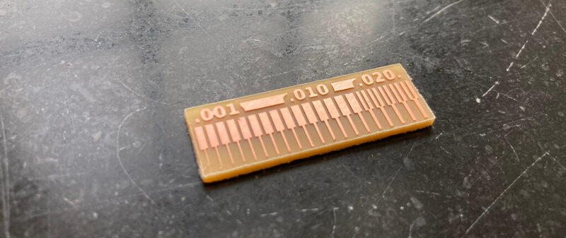
We began by milling a comb which shows the tolerances of the milling bit. Our group would test the 1 flute drill bit and the other group used the 2 flute drill bit.
The first step was to change the bit to the bit for trace milling. Then, we loaded the design, and lowered the milling head until it was approximately 1cm above the copper plate.
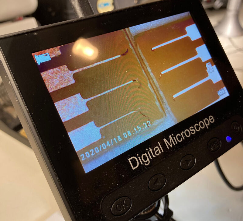
In the image you can see the two combs compared to each other under a digital microscope. On the left is the single flute comb and on the right the double flute comb. It is clear that the double flute drill milled more precisely.
Individual assignment
Make an in-circuit programmer that includes a microcontroller by milling and stuffing the PCB, test it to verify that it works.
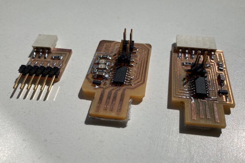
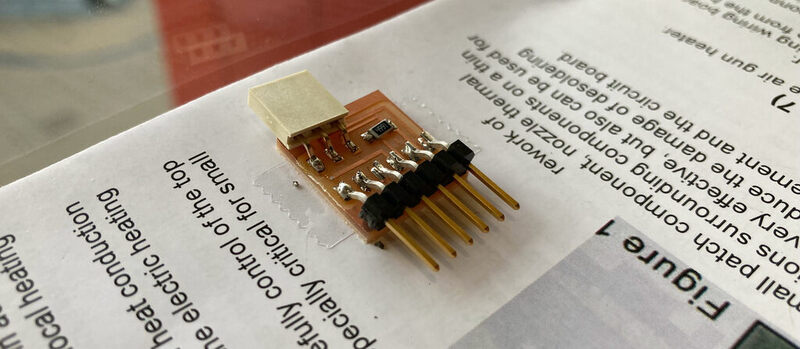
This week we will make three boards, an FTDI board, an FTDI to UPDI adapter and a SWD board. The first board I made was the FTDI to UPDI adapter. The milling went smoothly, and I was able to start soldering quite quickly after washing the board and removing the burrs. The boards I made are: * D11C-serial-1 sided * Programmer-swd-d11c * Serial UPDI-3 pin * and I attempted to make, but failed to, the hello.USB-serial.FT230X
Using the above links you can find the PNG files that I’ve used for this assignment. The process

I had a bit of difficulty finding all the components based on the numbers in the diagram, but with some help I was able to find them. I had a bit of confusion with the order of the resistors and the names of the connectors but Henk showed me where to find them. Henk helped me ‘flatten’ the UDPI connector afterwards, as it was raised off the PCB a bit by reheating the solder and pushing it down. Apart from that, the connectors were a little bit crooked but fine otherwise.
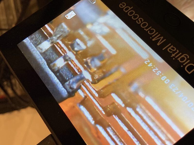
Moving on to the FTDI board, things started going less smoothly. My first issue was removing a short on the MC pins. There was some solder which was between two of the legs of the MC. I tried to remove it with the vacuum device as well as the braid. However, the solder remained. Finally, Henk helped me to completely remove the microcontroller and reattach it. Then using flux, we attached the component again.
After soldering the other components, I attached the board to my computer via USB and it started smoking. I removed the board and noticed there was some black stuff between the VCC and the ground leads coming from the microcontroller. It looks like there was still some flux residue between the the leads which cooked when the board was powered. Later Bas noticed that he and I had the same mistake on our boards, namely that there were two 1uf capacitors on the board instead of 10pf capacitors. Apparently, someone had put the wrong capacitors in the board. Henk told us to give up on the board.
By the next day, I had milled two boards and wanted to solder them. The first board I soldered was the programmer-swd-d11c. I made a number of mistakes with this board as well. Some pieces were not soldered and there was a short I had to correct.
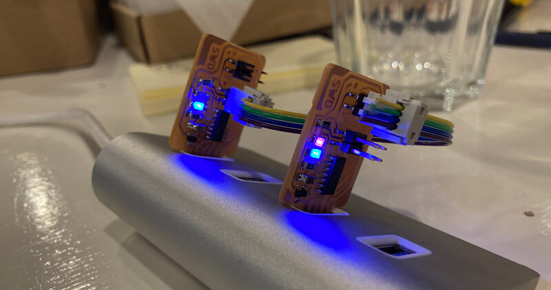
Finally, when the LEDs were lighting up correctly, I wanted to program the board using Henk’s programmer.
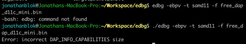
I was not able to program using edbg, so I installed openocd. I also downloaded the binary for the board (free_dap_d11c_mini.bin). Henk provided us with the config file. All I had to do was adjust the name in the openocd.cfg to the name of the binary.
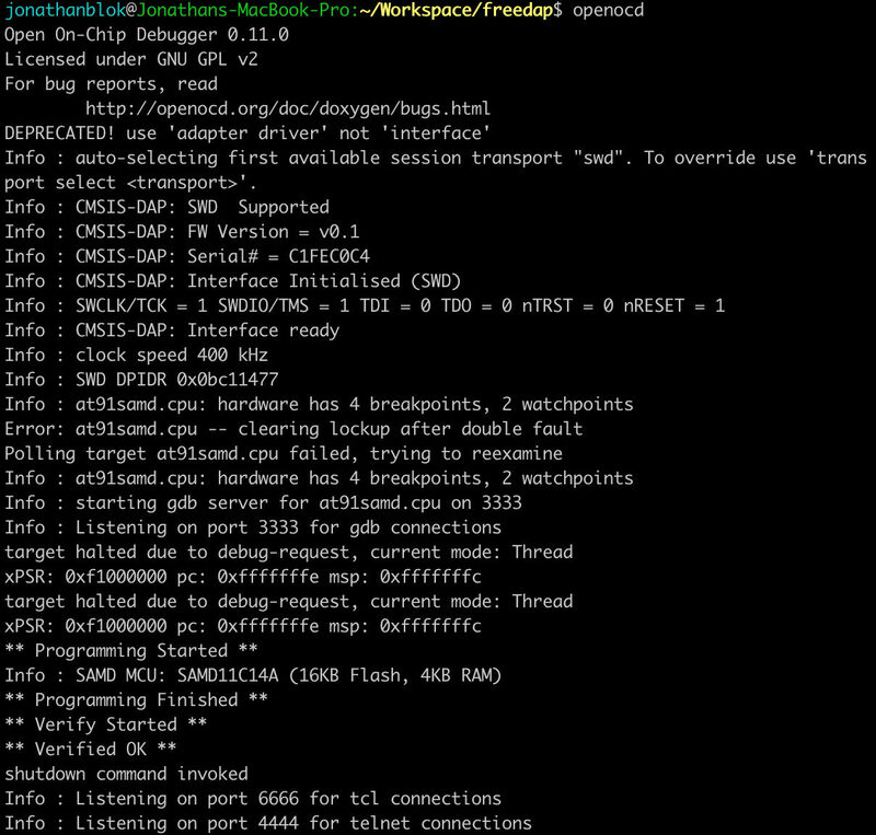
Using openocd I managed to program the board. Later I programmed some of the other’s programmers using my programmer.
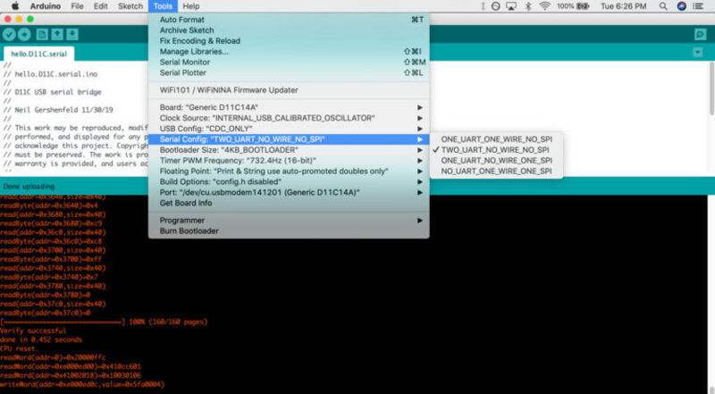
Soldering the last board, the SAMD11C14A, went quite smoothly. I made smaller mistakes soldering and only had to correct two small issues. I used the previously made programmer board to program the bootloader onto this board. I added a URL to my board manager in Arduino IDE from Quintin here. Then, I was able to select the presets for the SAMD board. The instructions are here.
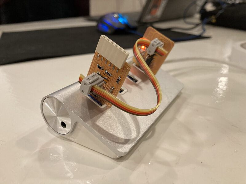
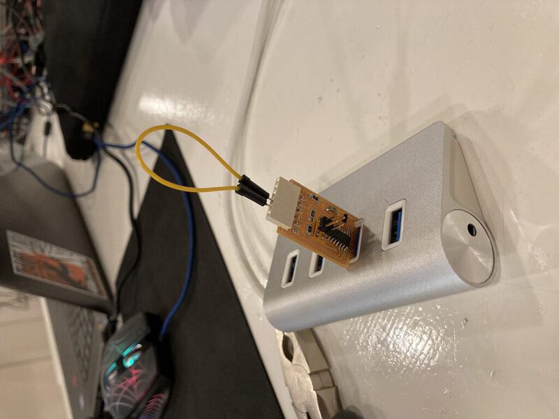
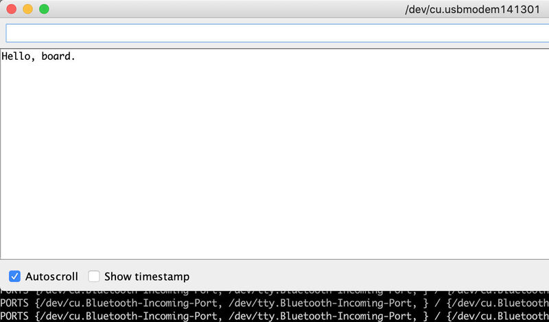
Finally, I tested my board by connecting the tx to rx using a cable and writing the hello.D11C.serial.ino program to the board. Then, using the serial monitor I was able to send and receive input. A final issue I ran into testing this board, very strangely that the SAMD11C14A only works when connected via USB hub, whereas the programmer-swd-d11c works both directly as via a USB hub. Also, when testing with someone elses FTDI on my old MacBook, it only worked when connected via USB hub.
void setup() {
   Serial.begin(0);
   Serial2.begin(115200);
   }

void loop() {
   if (Serial.available())
      Serial2.print((char) Serial.read());
   if (Serial2.available())
      Serial.print((char) Serial2.read());
   }