Week 3 - Computer-Controlled Cutting
Group assignment:
- Characterize your lasercutter’s focus, power, speed, rate,
kerf, joint clearance and types
Individual assignment:
- Cut something on the vinylcutter
- Design, lasercut, and document a parametric construction kit,
accounting for the lasercutter kerf,
which can be assembled in multiple ways,
and for extra credit include elements that aren’t flat
Lasercutter
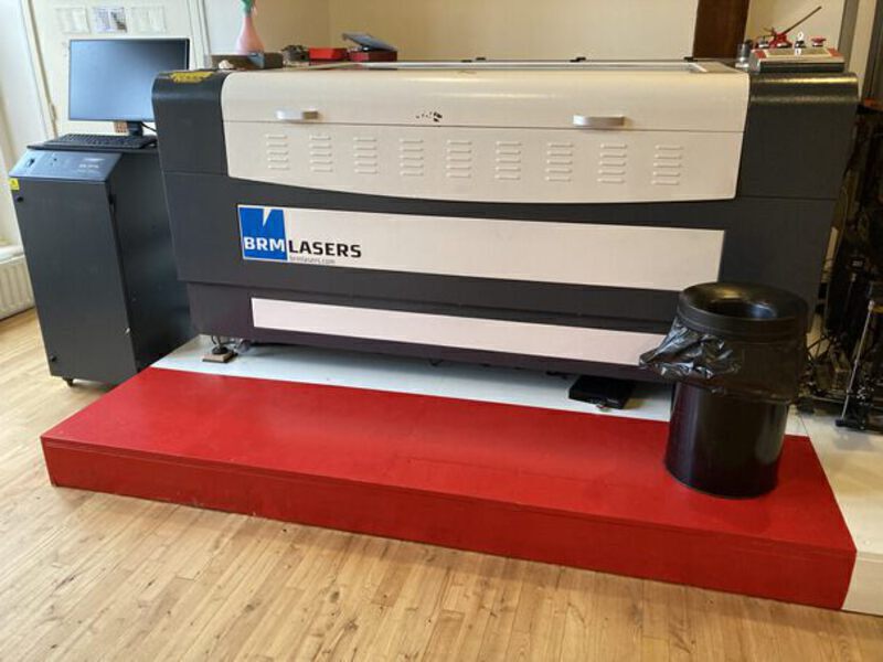
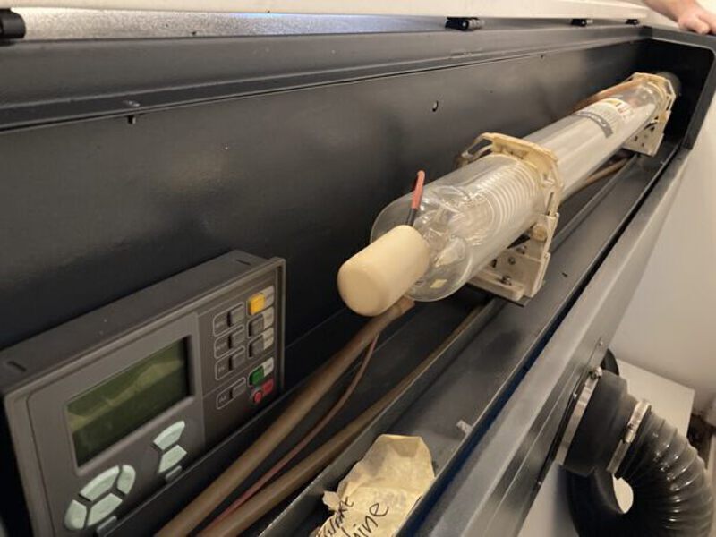
The laser originates behind the machine, and is redirected to the lasercutter head using mirrors.
Safety measures
- Lasercutters want to start fires. After cutting wait for a minute for exhaust fumes.
- The machine shuts off when you open the lid, there is a sensor on the right side of the lid.
- There is a fire extinguisher on the edge of the wall opposite the espresso machine.
Operating the lasercutter
- Turn key
- Turn machine on
- Switch laser on
You can use two interfaces when calibrating the machine, using the computer and LightBurn, or on the controller. The three main settings to calibrate when laser cutting are speed, maximum strength, and minimum strength. Speed determines how fast the laser head moves, the strength determines the intensity of the laser, and the minimum strength determines the intensity of the laser while following a path around a corner. Do not change machine settings, do not change controller settings, don’t change settings. Turn the machine on first, then LightBurn, then the fume extractor before you start laser-cutting.
Individual assignment
Creating a pressfit design
This week, I used the skills I learned last week in creating a parametric design to create a pressfit design. I decided to go with a basic shape for my first lasercut design, to determine how to work with kerf. It took me a very long time to correctly add the constrains and user parameter to the shape so that I ended up with the tabs and slots. Very often when I drew the lines on my shape, they remained blue, meaning that there was a problem with the constraints. Later I found out that my approach was not very good, after printing once I tried to adjust my design and the result was not what I had expected. I did not make too many screenshots at this time because I was frustrated.
The workflow I used for preparing the files was to create a drawing in Fusion, and then export it to PDF. Then, in Inkscape I preprocessed the file a bit i.e. crop it and remove any text that Fusion added. This is one of the first attempts at the design file. It would be nice to automate this workflow, because in my case I would always want the top view and the scale to be 1:1. It turns out there is much easier workflow to use that Joany showed me, which uses the DXF for Laser plugin for Fusion. This plugin allows you to export bodies directly to DXF.
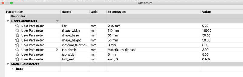
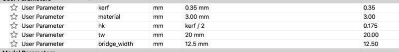
I used parameters to easily control the dimensions of the shape rather than inputting the values directly into the design. This way the parameters are all stored centrally, and changes to the parameters are reflected in all places that they are used in the model.
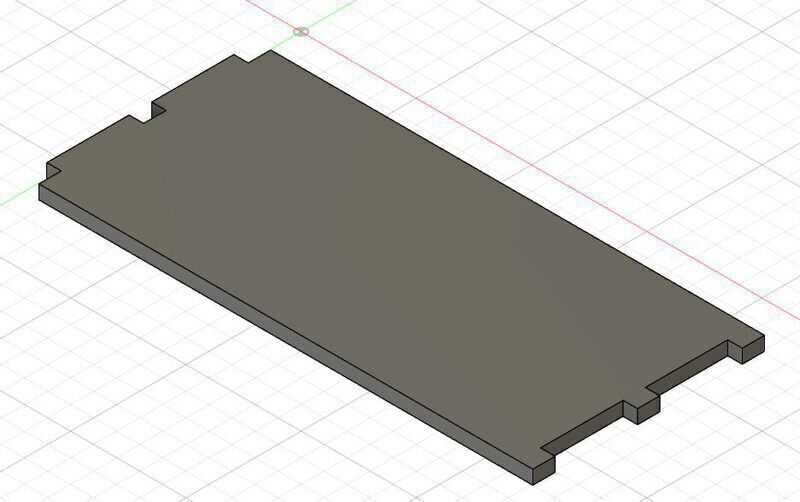
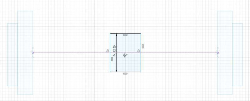
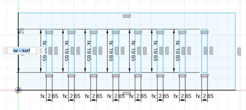
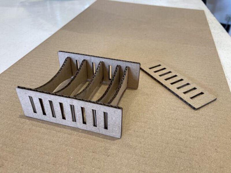
My second attempt at a design was to create a design with two side pieces, which are held together by center slots. I created two tabs and two larger rectangles which would stop the tabs from going in further. I added a parameter to determine the width of the center bodies as well as compensate for the kerf, but I had difficulty keeping the middle sketch centered around the axis of the outer sketch. When I changed the size the design would become lopsided. Finally, the way I managed to do this was by creating a center construction line between the two outer rectangles, and one inside the middle rectangle and using the colinear constraint.
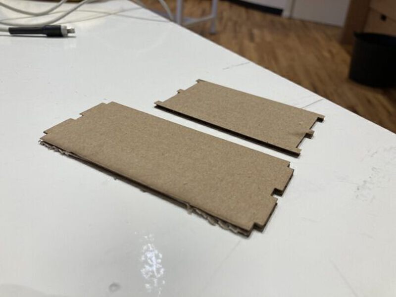
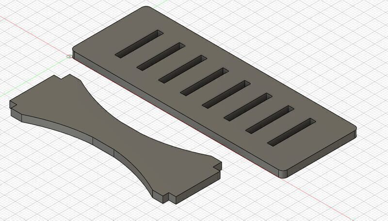
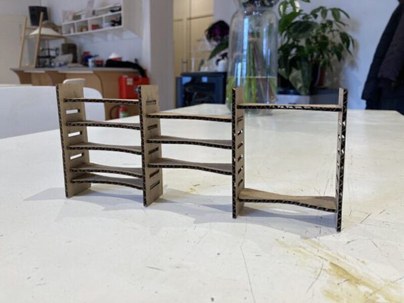
Then after extruding the shapes by the material thickness (3mm in this case), I created a loft between the three shapes resulting in a friendlier shape. Finally, I also filleted the corners of the side piece. Here is corresponding SVG file. The center pieces and edge pieces can be constructed in different ways.
The way I accounted for the kerf in these models was to add the calculated kerf to all outside and inside lines on the axis that the lasercutter will go along. For instance, for a rectangle, half of the kerf will be removed with every pass of the lasercutter. So if the lasercutter makes one pass on the top and one at the bottom, the kerf is removed once. Therefore, I add it once for every side.
Group assignment
This week we learned to use two new machines. The lasercutter and the vinyl cutter. We spent by far the most time on the laser cutter because it is most complex and dangerous. Neil said that lasercutters want to start fires.
For the assignment I worked together with Sander. Each group was assigned a material and we were left with the same material Henk used for the intro which is 3mm corrugated cardboard. Corrugated cardboard means that there are springs between sheets of cardboard. There is no separate page for the group assignment, we will each document on our respective pages.
The lasercutter’s specs (from waag.org):
Type/model: BRM1612
Max. work area: 1200x1600 mm
Lasertype: CO2
Power 100 W (Working life: 1500-3000 hrs)
Adjustable height workbench: 300 mm
Engraving Speed: 750 mm/sec
Cutting speed: 400 mm/min
Laser output: 1-100%
Accuracy: Less than 0.01mm
Scanner resolution: 50-1000 DPI
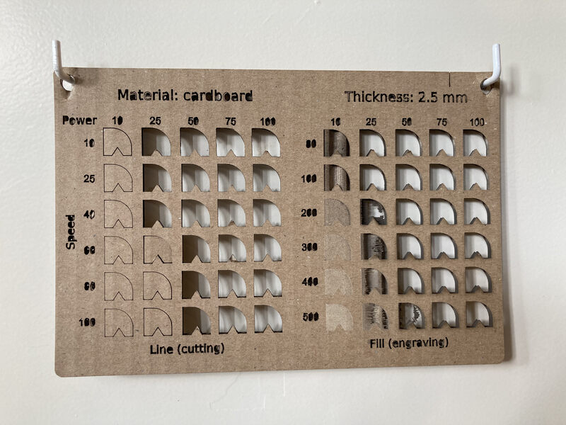
We determined the settings for the lasercutter by looking at these test cuts that are on the wall next to the lasercutter. Based on the test cuts we set the power to 70 and the speed to 100.

In order to estimate the kerf, we cut 10 rectangles from corrugated cardboard. Our intention was to use the 20 cuts on the y-axis and the 20 cuts on the x-axis, each with 0.5 kerf, to estimate the kerf. However, due to the corrugation the cuts along the x-axis fit into each other and we were not able to measure them accurately.
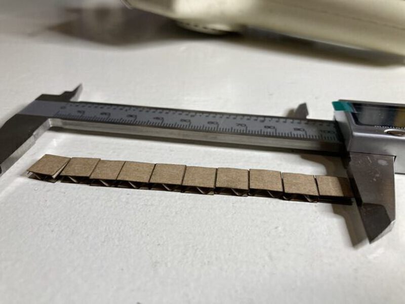
So we were left with 20 cuts on the y-axis, each missing the radius of the kerf. Our measurement was for the total was 2.7mm which makes the kerf 0.27mm. Adjusting for the kerf can be done on the laser cutter, but also in the model. Here is the model we used.
Our assignment is to characterize our lasercutter’s focus, power, speed, rate, kerf, joint clearance and types. Our lasercutter is old, and there are many caveats to using it. One of them is that the pulse rate i.e. frequency should not be changed. We started the assignment by calculating the kerf. A lasercutter operates by removing material from a sheet of material. The lasercutter’s instructions tell it the path to cut, but because it removes material, the resulting shape might be smaller than in the model.
The lasercutter’s focus is at 12.06mm from the nozzle. It must be calibrated before using the lasercutter. The Tab Pulse Width is set to 0.05mm, and should not be adjusted.
TODO: combine and discuss results from other groups.
Vinylcutter
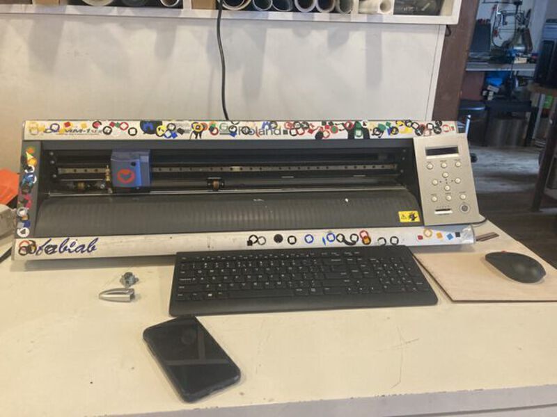
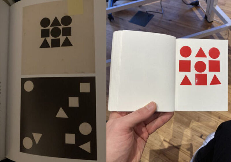
I created a design based on a painting by Gertrud Arndt (link), and followed the following steps to print it on the vinylcutter.
- I transferred the design to the machine as plain svg using a USB drive.
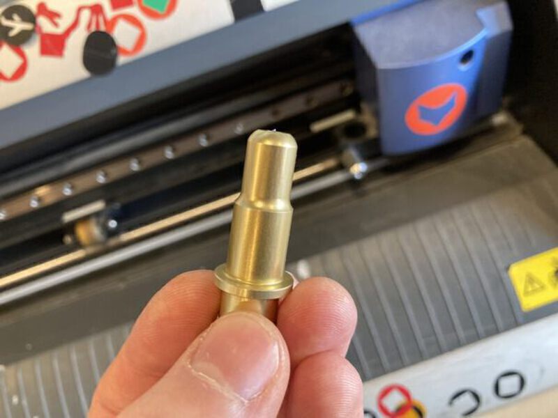
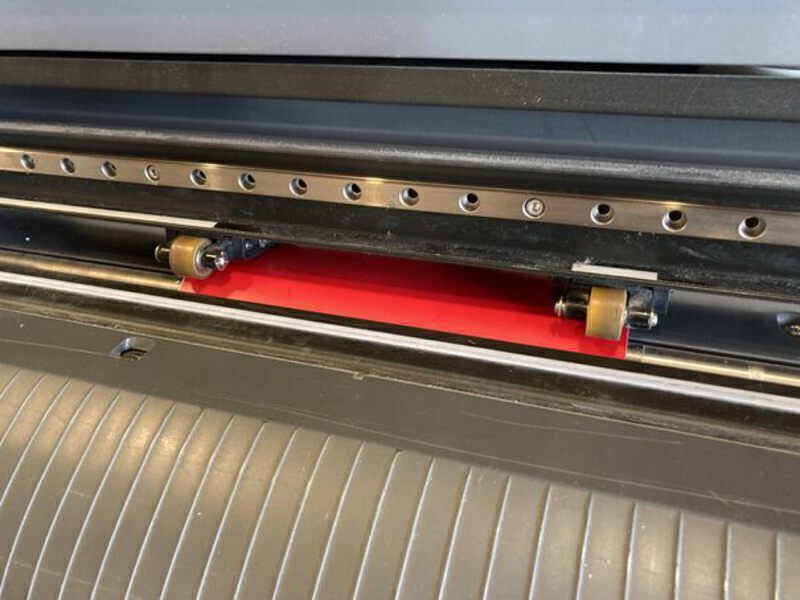
- I checked the blade by removing the head and checking the protrusion.
- I checked lever position. Lever down means sheet/roll cannot be pulled. Lever up (towards the top of the machine) means the wheels are grabbing the sheet/roll.
- I advanced the sheet/roll to beyond the white line, otherwise the sheet/roll will be pulled into the machine and be damaged.
- Turned on the Vinylcutter.
- Loaded the sheet/roll and selected the appropriate setting. In this case I am using a sheet.
- Once the sheet was loaded, you can run a test on the material to see if the force is sufficient. It will cut out a circle and a square.
- To run your job, open your file in Inkscape and open the Inkcut extension.
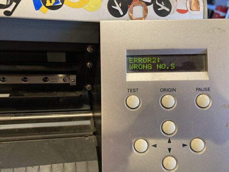
Problem: the vinylcutter cut the travel lines as well as the cut lines, and there is an error showing on the display.
Solution: recalibrated knife position by removing the head and reducing how far the knife sticks out. Reduced pen force as well, as it was set to +1.5gf.
Outcome: the next cut piece came out with the issue persisting.
Solution: Switch to mods as I was unable to fix the issue using Inkcut.
Outcome: The job completed succesfully.
Also you need to align the rollers to an area with a white line indicating there is sensor coverage there. Otherwise, a ‘Bad position’ warning will be given.
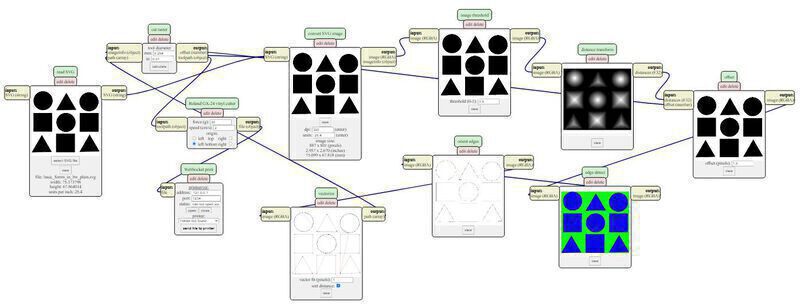
- To use mods I looked in the bash history how Henk had started it previously. In the home directory there is a directory ‘mods’ in which you can run
bash modsto start mods. Then you can go to a local instance of mods in a browser. Here you can add the vinylcutter. - Load an SVG in mods by clicking in the window on the left.
- Press calculate to render the SVG, and then send it to printer.
- Weeding a design which you want to stick to a surface is made easier by first attaching the design to the destination surface.