Networking and communications
Group assignment:
Send a message between two projects
Overview of Chip to Chip Communication Protocols
Nearly all PCBs contain multiple ICs, which necessary to the boards to communicate with each other, usually users need data transfer along multiple PCBs. SPI, I2C, and UART are the most often used protocols in these kinds of connections. Here, some of these protocols' main characteristics and certain design principles for ensuring high-fidelity communication are presented.
SPI (Serial Peripheral Interface):
SPI is a synchronous duplex communication protocol, allowing for simultaneous data transmission and reception. Master Out Slave In (MOSI), Master In Slave Out (MISO), Serial Clock (SCLK), and Chip Select are the commonly used four wires (CS). In the diagram below, a typical SPI communication is depicted.
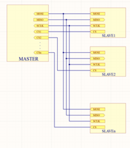
Multiple slaves can communicate with one master, but each slave needs a chip select signal. This indicates that the master will need n+3 pins for every n slaves.
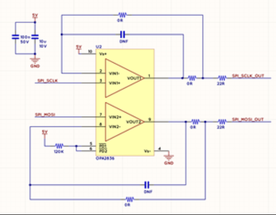
SPI communication may occur at speeds of up to 100MHz. However, various extra circuitry may be required to communicate quickly. Overshoot and ringing are the high speed SPI signal's most typical issues. By adding a modest series resistance to the signal route, this issue may be solved easily. The output and clock lines should be buffered if the communication distance is great. Below is an example buffer circuit: In the image below, n is depicted.
I2C (Inter-Integrated Circuit):
The I2C standard is commonly used for inter-IC communication. It communicates using a data line (SDA) and a clock line (SCL). As long as the bus input capacitance is under the I2C standard's maximum, any number of slaves can be linked to a single master. Up to 5MHz of speed is supported.
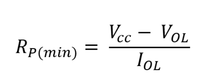
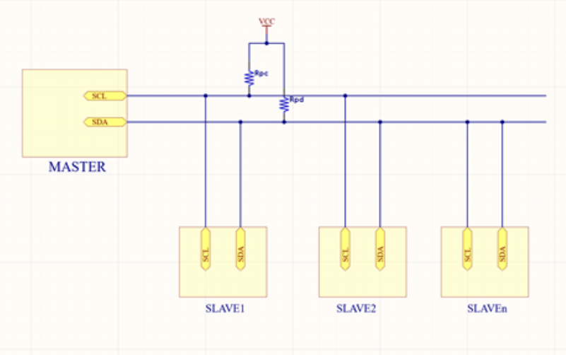 Since the communication standard is open-drain, a pull-up resistor is required. ICs with various supply voltages can now connect to the same bus thanks to this. An essential design factor is the pull resistor's value. The IC won't be able to pull the line LOW if we use a low resistor. The least permitted pull-up resistance is determined as follows if the low-level voltage VOL and sink current IOL are:
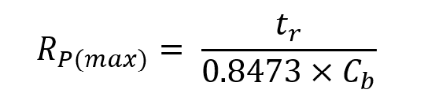
On the other side, it will take a long time to charge the input capacitor if we choose an extremely high pull-up resistor. As a result, the signal might not reach the logical high before being pushed low. For high-speed data transport, this is particularly important. The maximum permissible pull-up resistance may be determined as follows if tr is the signal's rise time and Cb is the bus's capacitance:
UART (Universal Asynchronous Receiver Transmitter):
Two chips are linked directly via the UART protocol. One chip's Tx is linked to the other's Rx, and vice versa. Because this protocol is not scalable, only two chips can communicate with one another over a single UART line. The following is a block diagram of UART communication:
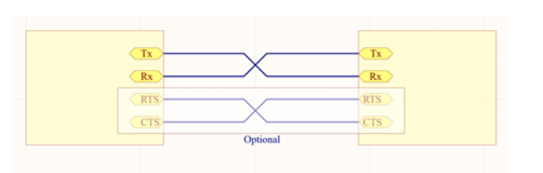 Since there is no clock transmitted, the receiving chip must be aware of the speed of the other chip's transmission. The UART line should have a series resistor added, similar to how SPI is done to account for overshoot and ringing. The single-ended nature of the signals makes them more susceptible to noise, particularly over long distances. To increase the integrity of the connection, two additional signals, CTS (Clear to Send) and RTS (Request to Send), are occasionally introduced.
source
Since there is no clock transmitted, the receiving chip must be aware of the speed of the other chip's transmission. The UART line should have a series resistor added, similar to how SPI is done to account for overshoot and ringing. The single-ended nature of the signals makes them more susceptible to noise, particularly over long distances. To increase the integrity of the connection, two additional signals, CTS (Clear to Send) and RTS (Request to Send), are occasionally introduced.
source
Bluetooth Module
HC-05 module is an easy to use Bluetooth SPP (Serial Port Protocol) module, designed for
transparent wireless serial connection setup.
Serial port Bluetooth module is fully qualified Bluetooth V2.0+EDR (Enhanced Data Rate) 3Mbps
Modulation with complete 2.4GHz radio transceiver and baseband. It uses CSR Bluecore
04-External single chip Bluetooth system with CMOS technology and with AFH(Adaptive
Frequency Hopping Feature). It has the footprint as small as 12.7mmx27mm. Hope it will simplify
your overall design/development cycle.
source
Group assignment
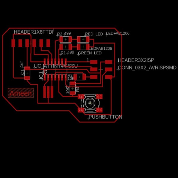
We work in group assignment to control led intensity with potentiometer, the led connected with slave controller board (aybake board
) and potentiometer with master controller board (my board)
Wiring connect the potentiometer signal with pin number A0 in master board and connect the led with pin number 5 in slave board, finally connect TX in master board with RX in slave board and RX in master board with TX in slave board.
File to Download.
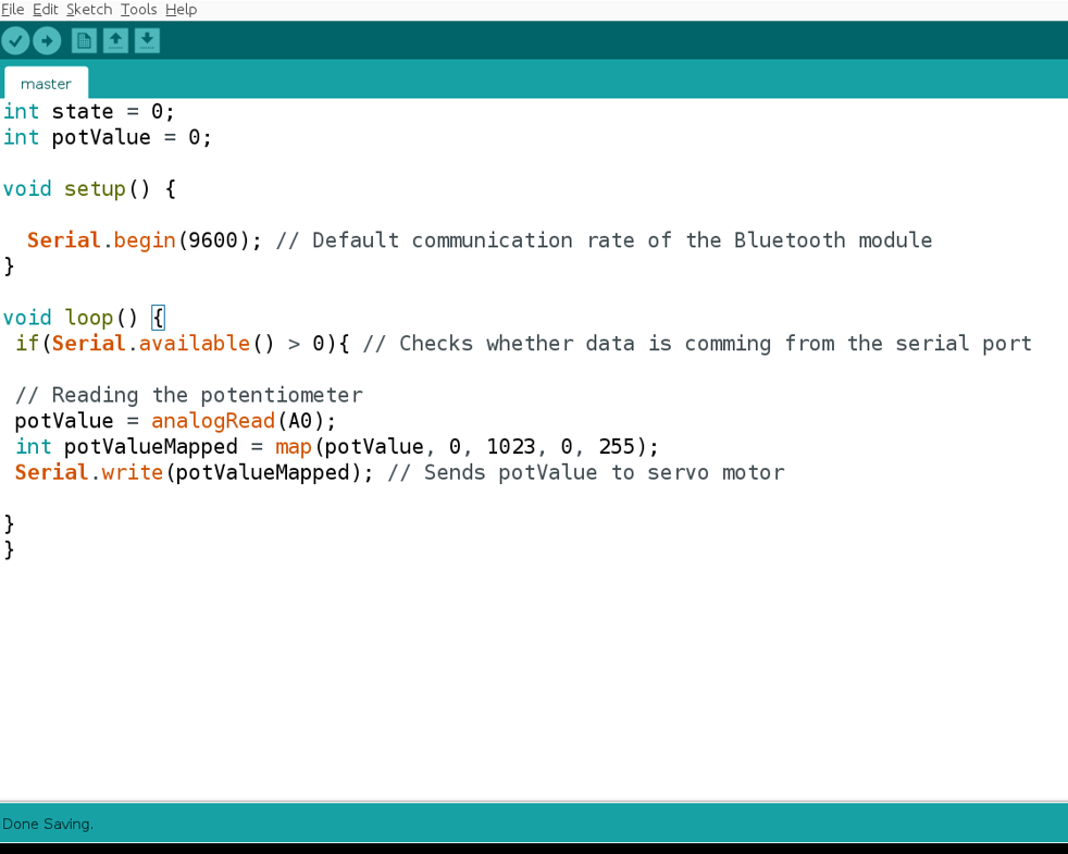
Code for Master
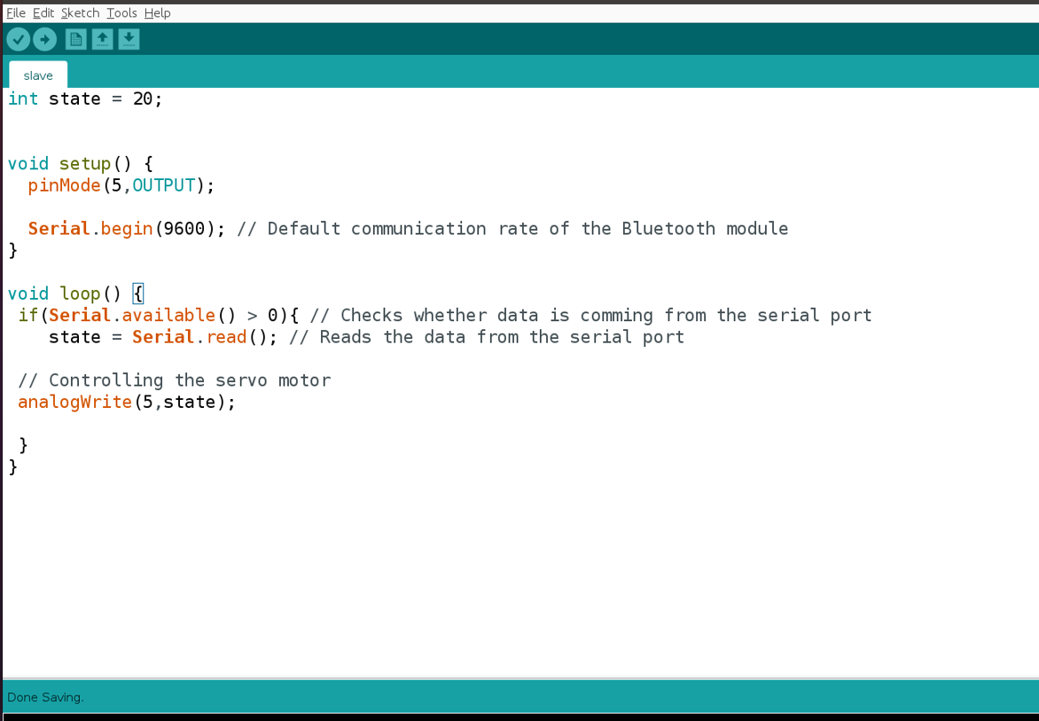
Code for Slave
Note : the baud rate must be the same in master and slave board
Code for Master board
Code for Slave board.
Hero Shoot !
Individua Assignment
Design, build, and connect wired or wireless node(s) with network or bus addresses
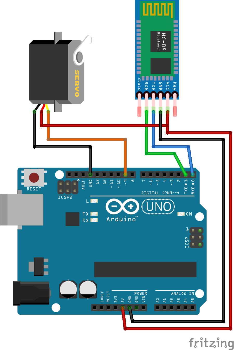
I worked in the individual assignment to control the servo motor using my phone , I connect the bluetooth HC-05 module to amino board and send the signal use my phone, this works based on
Source
Wiring
-Connect the black wire of each servo motor to GND.
-Connect the orange wire of motors to the 5V from boardy.
-Connect pin 9 in Arduino order to the Orange wire of the motor.
-Connect the board's 5V to the VCC of the Bluetooth module.
-Connect the board's GND to the GND of the Bluetooth module.
-Bluetooth module TX should be connected to RX pin .
-Bluetooth module RX should be connected to TX pin .
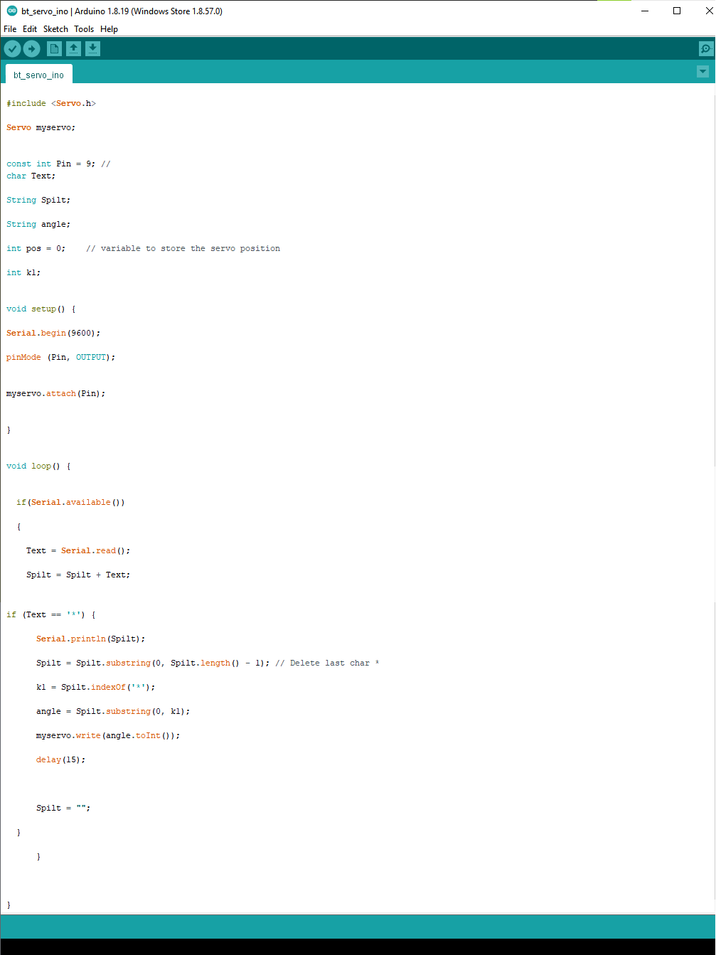
Code
File to Download
Control servo motor with bluetooth Code
App for 180 degree
App for 360 degree
Hero shoot!