Output Devices
Group Assignment
-Measure the power consumption of an output device
-Document your work to the group work page and reflect on your individual page what you learned
In this section we calculated the power consumption of a DC motor . the power (in Watt) is calculated by P = V x I ,where V is the voltage across the load and I is the current travelling through the load, to measure the voltage and current we used The digital multimeter (DMM) where it connected in parallel with the load to measure voltage, and it is connected in series with the load to measure current going through. Before connecting in series with the load, remember to shift the DMM positive test lead tocurrent measuring position
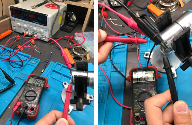
To calculate how much power the DC motor uses,
P = 12.61 x 0.092
P = 1.16 Watt
P = 1160 mWatt
2. Individual Assignment
Add an output device to a microcontroller board you've designed and program it to do something
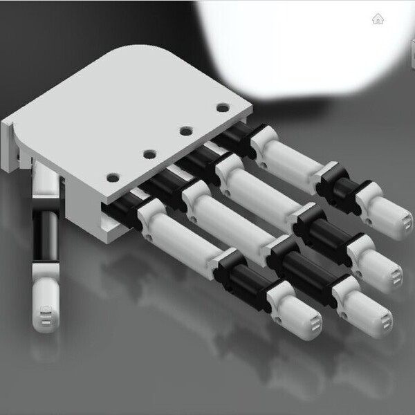
This week's assignment is to create a board that will assist in the operation of an output device. so, I learned about the mechanisms and functions of many types of motors. Before I used these Servo Motors as my output device for this week.
An Overview of Servo Motors
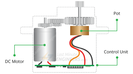
A servomotor is a rotary or linear actuator that can regulate angular or linear position, velocity, and acceleration with precision. [1] It is made comprised of an appropriate motor and a position feedback sensor. It also necessitates a complex controller, which is frequently a separate module created exclusively for servomotors. Although the word servomotor is typically used to refer to a motor appropriate for use in a closed-loop control system, it is not a specific type of motor. Servomotors are utilized in robotics, CNC machines, and automated manufacturing, among other uses.
How does servo motor works:
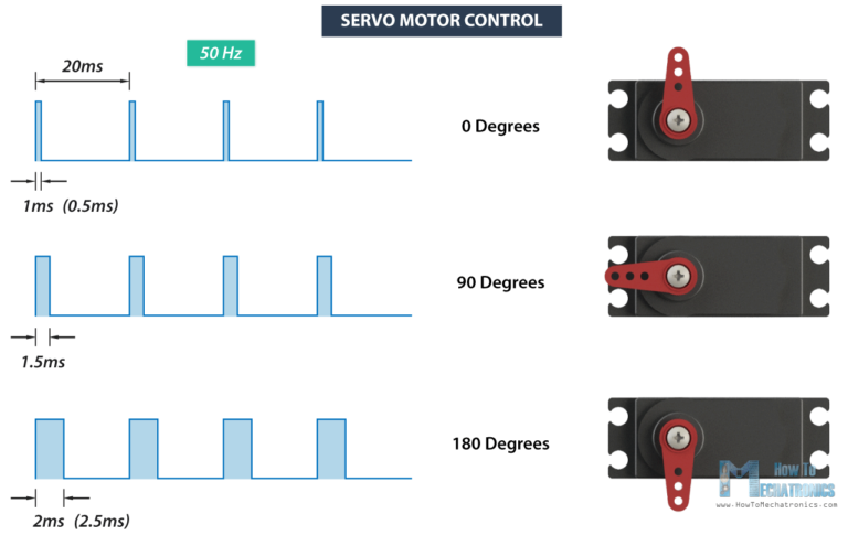
Servos are controlled by transmitting a variable-width electrical pulse across the control line, often known as pulse width modulation (PWM). There are three types of pulses: minimum, maximal, and repetition rate. A servo motor can only rotate 90 degrees in either direction for a total of 180 degrees.Source
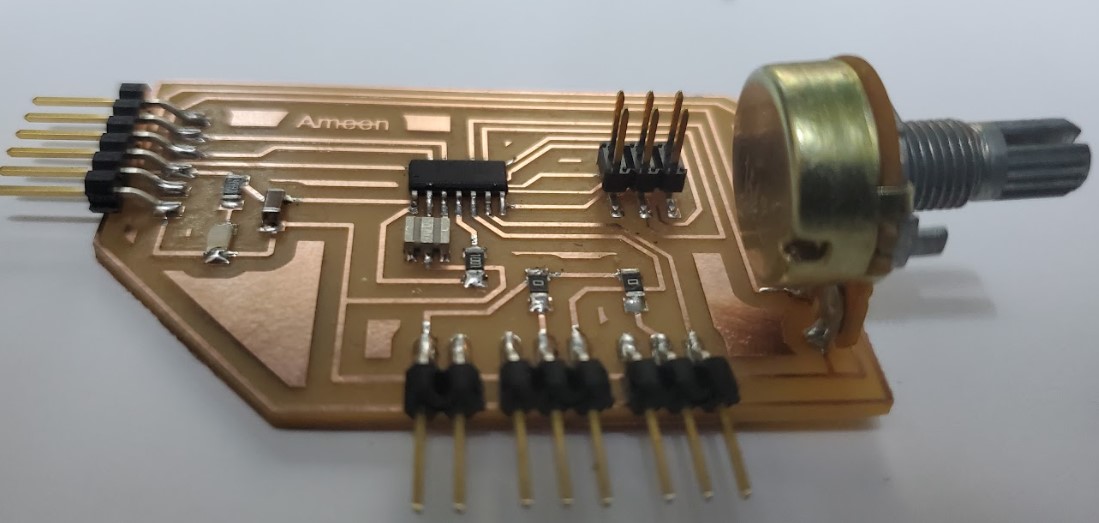
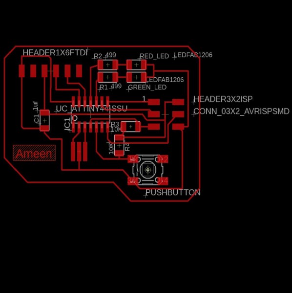
2.1. PCB desgin use Eagle
I started the design from the previous board that was designed in the Electronics Design Week. The aim of this assignment was to control the servo motor through a potentiometer. This is due that I have a lot of servo motors in my final project, so I need a servo tester .
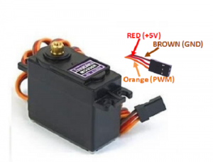
As previously explained, the servo needs three lines: VCC, GND, and PMW signal, and the potentiometer needs a VCC, GND, analog input, so the old board will be modified by taking out the 3 pin headers of the servo motor and connecting the wires to the Potentiometer
Referring to the Datasheet of attiny44 , the select is BMW pin and analog pin, the pin No. 7 & 8 was selected for the motor and the pin No. 3 for the Potentiometer in arduino code
File to Download
Eagle file
The pictures show the steps for designing the board. At first, we start with a schematic diagram, then draw traces on the board, and then export the pictures to fabricate board.
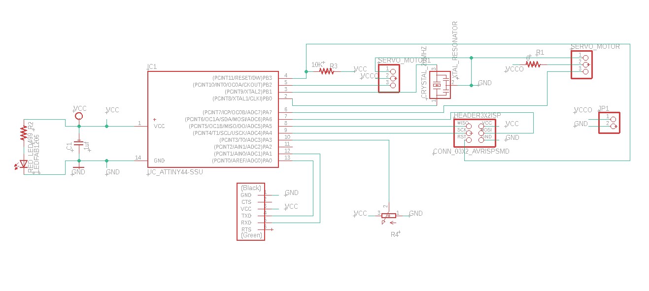
| Description | Reference | Lib Name | Quantity |
|---|---|---|---|
| ATtiny44 | IC1 | UC_ATTINY44-SSU | 1 |
| Crystal 20MHz | XTAL1 | XTAL_RESONATOR | 1 |
| Header 3x2 ISP | J1 | CONN_03X2_AVRISPSMD | 1 |
| Header 1x6 FTDI | J2 | CONN_06_FTDI-SMD-HEADER | 1 |
| Capacitor unpolarized 1uF | C1 | CAP_UNPOLARIZEDFAB | 1 |
| Resistor 10kOhm | R3 | R1206FAB | 1 |
| Resistor 499kOhm | R2 | R1206FAB | 1 |
| Resistor 0Ohm | R1 | R1206FAB | 1 |
| Red LED | D1 | LEDFAB1206 | 1 |
| Potentiometer | R4 | 3RP/1610N | 1 |
| Header 1x3 | Servo motor | PINHP-1x3 | 2 |
| Header 1x2 | JP1 | PINHP-1x2 | 1 |
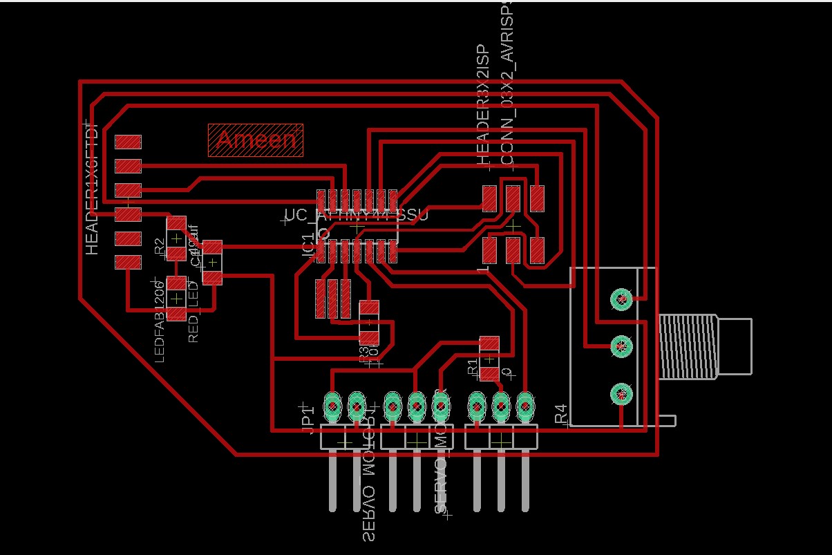
When you export the image it should be like this
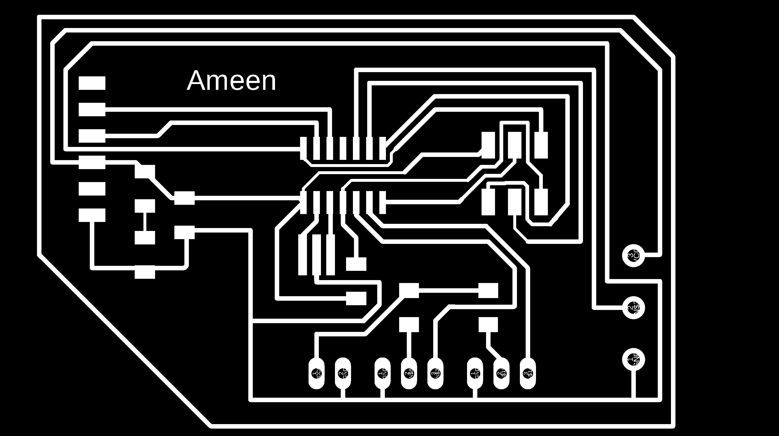
use paint to remove the outline it should be like this
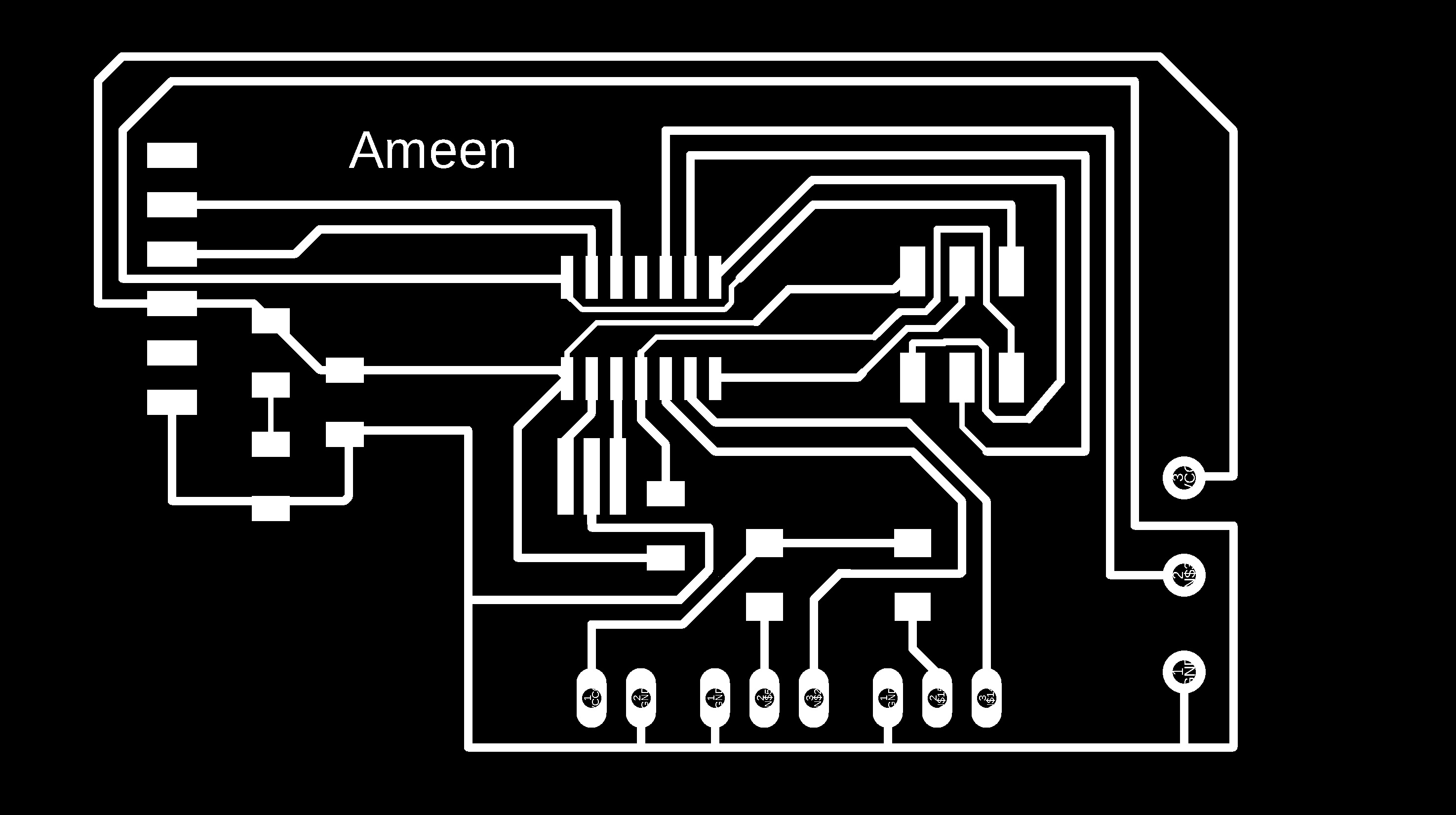
use paint to remove traces and keep the outline it should be like this
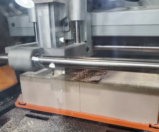
2.2. Milling Process
File to Download
Trace.png
Trace.rml
Outline.png
Outline.rml
Modes
Step 1: Open Mod and Right click any whare. select programs - open server program - PCB png from Roland SRM-20 list.
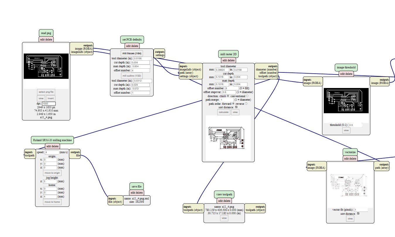
Step 2: On the “read png” block Click on select png file and choose the "trace.png"
Step3: Select mill trace from “set PCB defaults” block.
Step4: On the “Roland SRM-20 milling machine” block let the origin coordinates 0,0,0
Step8: Right click and select modules - open server module- save.
Step9:- replace "websocte device" block with "save file" block .
Step10:- Click on calculate in "mill raster 2D" block , The RML file will be downloaded automatically.
Note : you can have better finish if you make the offset more than 4 like 6 but it will take more time.
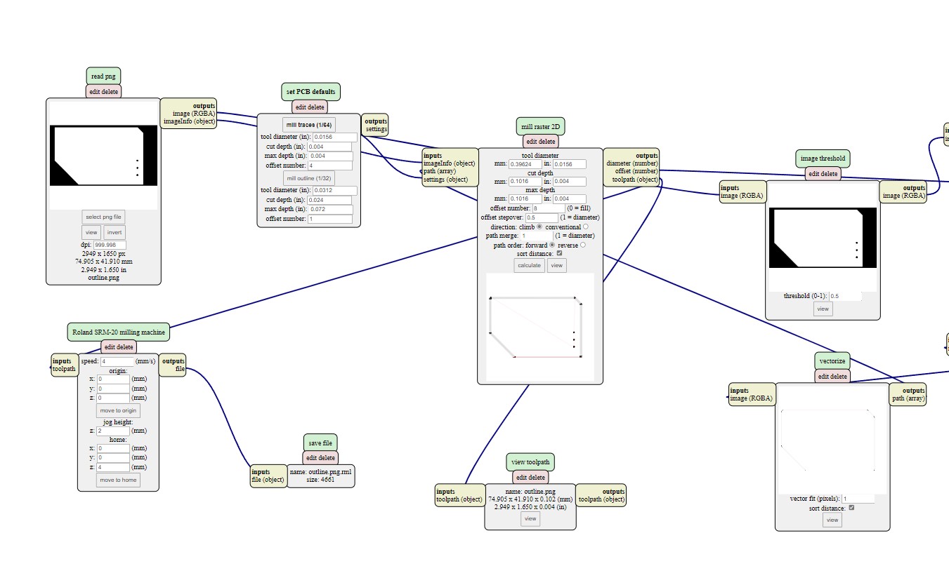
Step11:Repeat the previous steps on the outline.png file, but click on the mill outline rather than mill traces from set PCB defaults block , to have outline.rml file
Note: check the job dimention before calculate.
Step 1: Open the VPanel program and go to the dropdown menu and pick "Machine Coordinate System."
Step 2: move the head over the bottom left corner of the PCB, use the arrows in red box. then raise the head , use the "+Z" arrow to create enough space between the spindle and the PCB.
Step 3: Install the 1/64" milling bit in the spindle collet, keeping roughly 25% of its length outside.
Step 4: Using the "-Z" arrow, lower the spindle until the distance between the PCB and milling bit tip are about 5 mm . Untie the fastening screw while holding the milling bit between your fingers. Lower the milling bit until it makes contact with the PCB. Tighten the fastening screw.
Step 5: Select "User Coordinate System" from the "Set Origin Point" by clicking on "XY" and "Z" in blue box . In the user coordinate system, this will make the current position the home or zero position.
Step 6: Move the milling bit a few millimeters above the PCB.
Step 7: Select "Cut" and then "Delete All" to get rid of any outdated jobs. Select the traces rml file by clicking "Add." finally Choose "Output" Now is the time for the machine to start.
Step 8: When the first job is finished, go to the "Move" menu and select "XY". The spindle will be moved to the "XY" home . lift up milling bit , cover it and remove it. after that install milling bit 1/32".
Step 9: Repeat steps 4 to 7 with "outline.png .rml"file, but don't change x , y coordinate for origin "home coordinate"
2.3. Soldering
Use the schematic as a reference for component values and placement while soldering the parts to the PCB.
Note the components that must be installed in the correct orientation:
-The LED cathodes on the PCB drawing are marked with dots and thicker lines. If you do not find the dots and thicker lines , determine the cathode using a multimeter.
-The ATtiny45 marks pin 1 with a dot laser-etched into the corner of the package. Pin 1 is marked in the drawing with a dot as well.
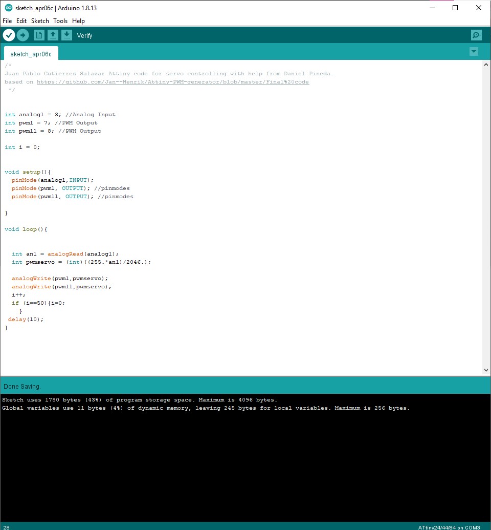
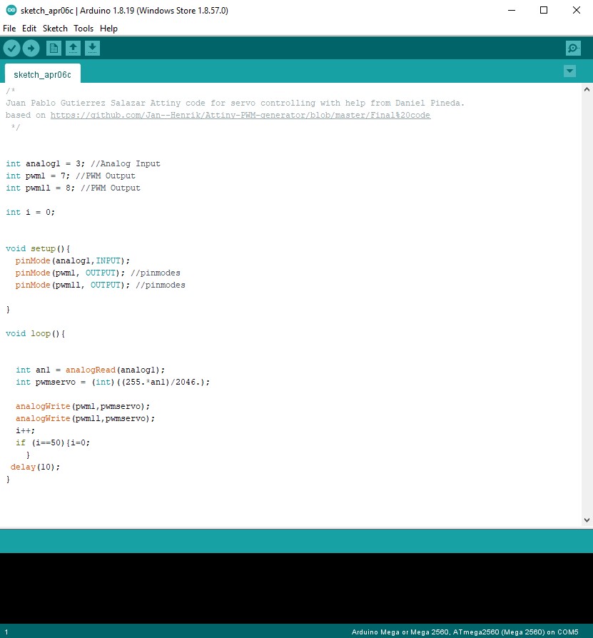
2.4. Programing
Two Code has been written. The first is to ensure that the motor is working, and the other is to control the motor through the potentiometer
File to Download
COD#1
COD#2
Problem
A problem has been encountered in the programming while the servo library does not work with the attiny controller, so it cannot be used. thanks for Juan Gutierrez for this information.
2.5. Result


