12. Output devices
This week I worked on defining my final project idea and started to getting used to the documentation process.
This weeks Assignment: 
-
Individual assignment:
-
Add an output device to a microcontroller board you’ve designed,and program it to do something.
-
Group assignment:
-
measure the power consumption of an output device.
For this weeks group assignment you can check our page by clicking here
First part:(individual assignment) : 
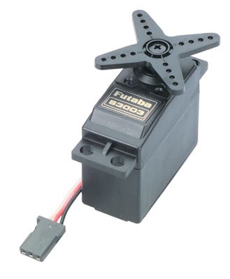
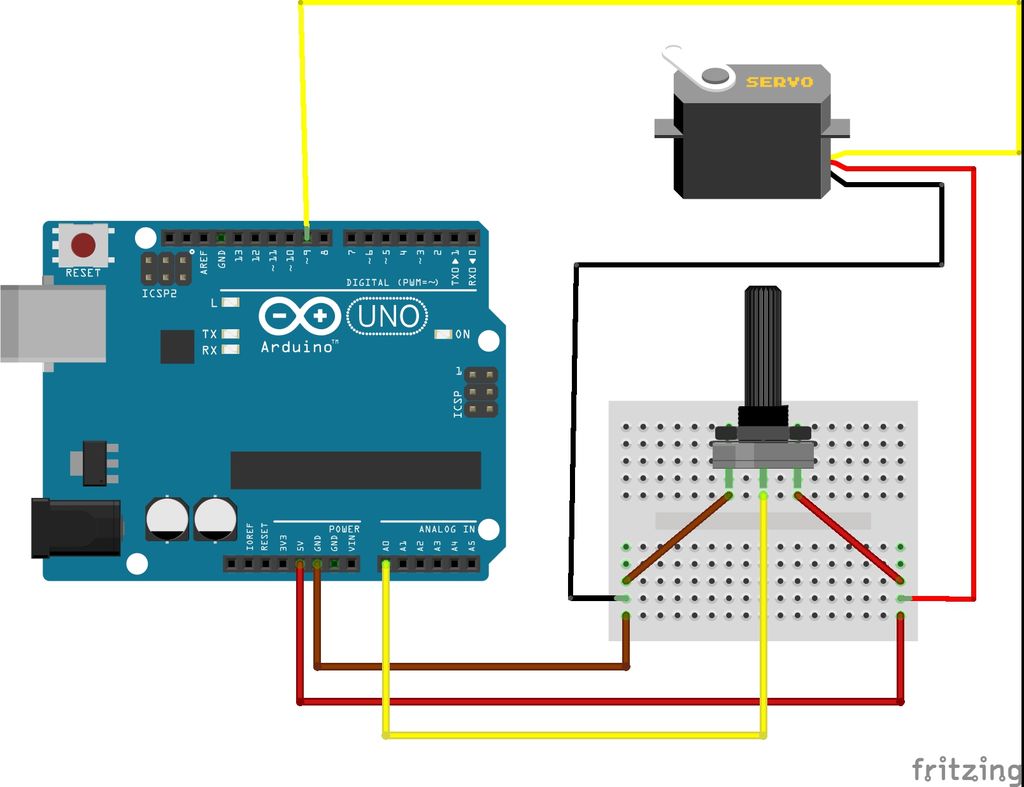
For this weeks assignment I choose to work with a servo motor with a potentiometer as an output device .
So, what is an output device
*An output device is any piece of computer hardware equipment which converts information into human-readable form. ... Some of the output devices are Visual Display Units (VDU) i.e. a Monitor, Printer, Graphic Output devices, Plotters, Speakers etc.
what does sensor mean?
* A sensor is a device, module, machine, or subsystem whose purpose is to detect events or changes in its environment and send the information to other electronics, frequently a computer processor. A sensor is always used with other electronics it responds to a physical stimulus (such as heat, light, sound, pressure, magnetism, or a particular motion) and responds to it in a distinctive manner.
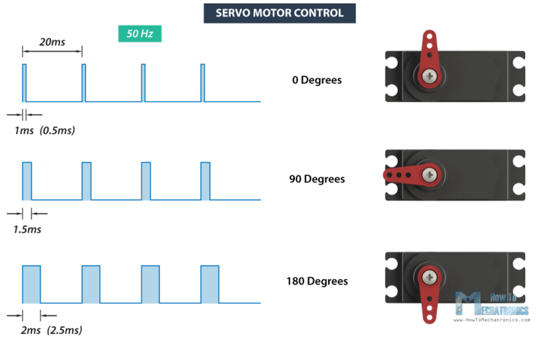
How does servo motor works:
Servos are controlled by sending an electrical pulse of variable width, or pulse width modulation (PWM), through the control wire. There is a minimum pulse, a maximum pulse, and a repetition rate. A servo motor can usually only turn 90° in either direction for a total of 180° movement.
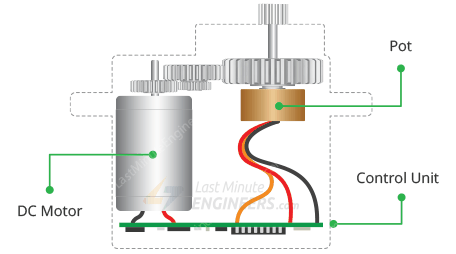
What is a potentiometer used for?
The measuring instrument called a potentiometer is essentially a voltage divider used for measuring electric potential (voltage); the component is an implementation of the same principle, hence its name. Potentiometers are commonly used to control electrical devices such as volume controls on audio equipment.
Let’s start:
- Use the jumper cables to link the arduino to the servo motor and the potentiometer, following the steps below:
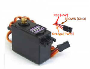
1- For the sevo motor:
- GND/GND
- VCC/5V
- PWM/PIN 9
2- Potentiometer:
- GND/GND
- VCC/ 5v
- Signal/ PIN A0
-
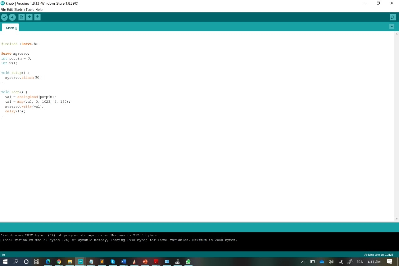
Now, Open the IDE and attach the arduino to the laptop .
-
Go file / New and write the code below:
#include <Servo.h>

Servo myservo;
int potpin = 0;
int val;

void setup() {
  myservo.attach(9);
}

void loop() {
  val = analogRead(potpin);
  val = map(val, 0, 1023, 0, 180);
  myservo.write(val);
  delay(15);
}
- Upload the code to the arduino :
- The job is done ^^
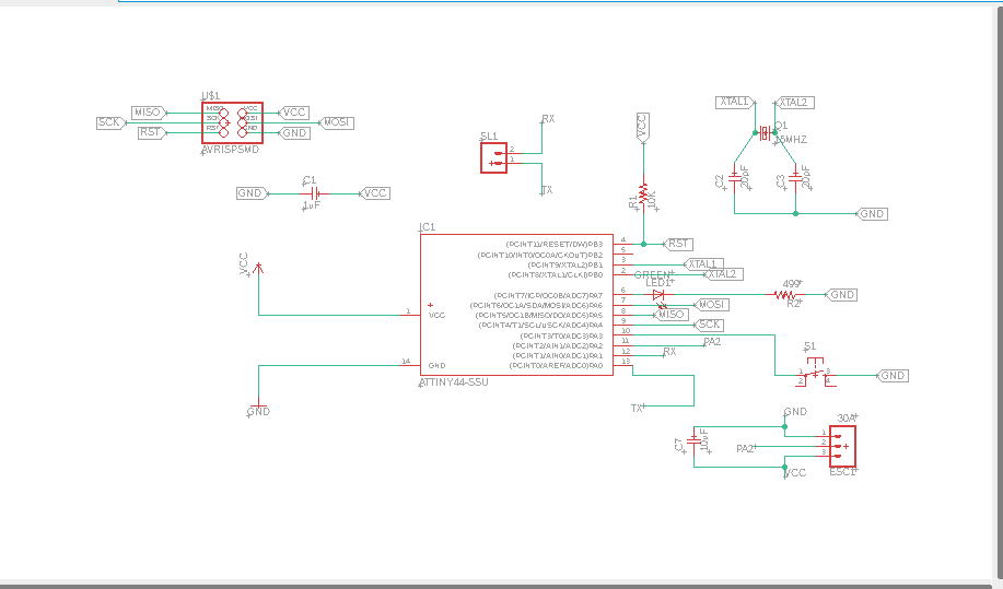
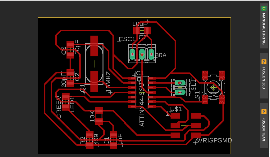
I tried to produce another new board for my output week in which I used the Attiny44 microship and the following parts:
- 20 Mhz resonator
- Capacitors 1uF
- 2 resistors 10k and 499ohm
- 6 header Pins for programming(ISP)
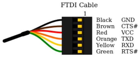
- 2 headers pins connector for the ftdi (RX AND TX)
- 3 headers pins for the ESC 30A of the brushless motor
- 10uF capacitor As it shown below :
This is the final board after linking all the parts together :
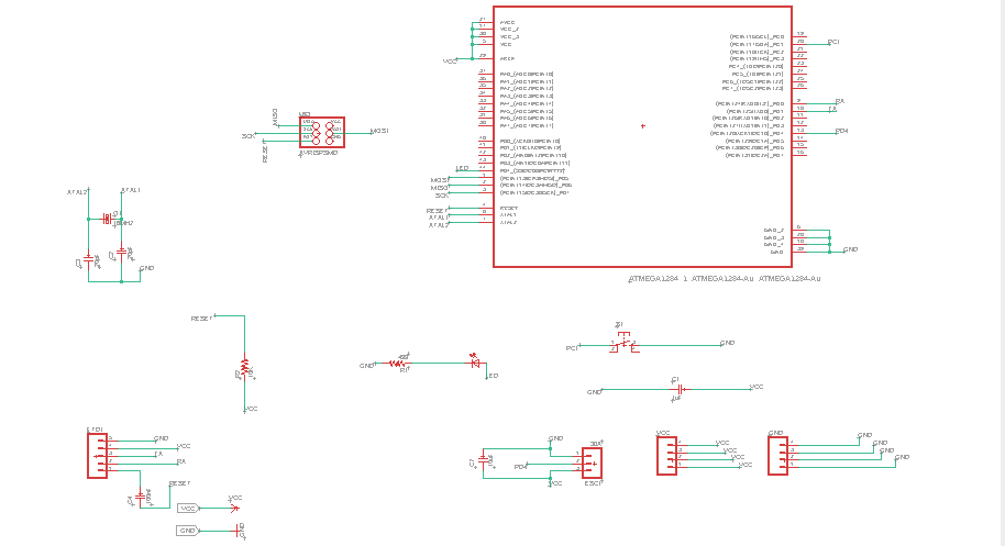
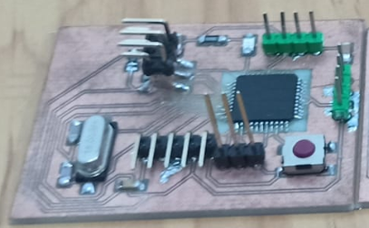
Unfortunatly, due to some reasons in my country I coudn’t find some of the SMD parts inclusing the Attiny44 for that reason, I tried to use another Micro controller which is the Atemega1284P and reprouced the card from the beginning , I kept the same componants as in the previous card and onlay I made some small changes as it is shown below :
- 16 Mhz resonator
- Capacitors 1uF
- 2 capacitors 10 uF
- 2 20 pF and 100 nF capacitors
- 2 resistors 10k and 499ohm
- 6 header Pins for programming(ISP)
- 5 headers pins connector for the ftdi (RX , TX , RESET , VCC AND GND )
- 3 headers pins for the ESC 30A of the brushless motor
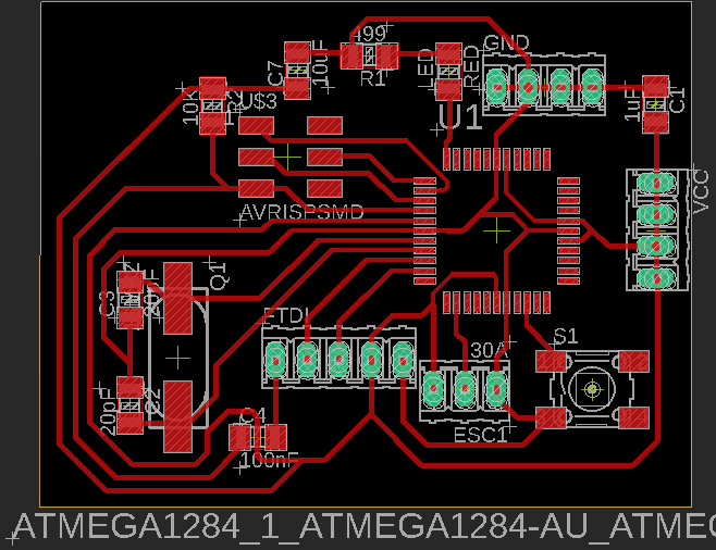
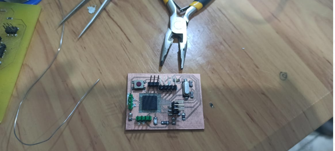
Here is the result I got after I linked all the parts together :
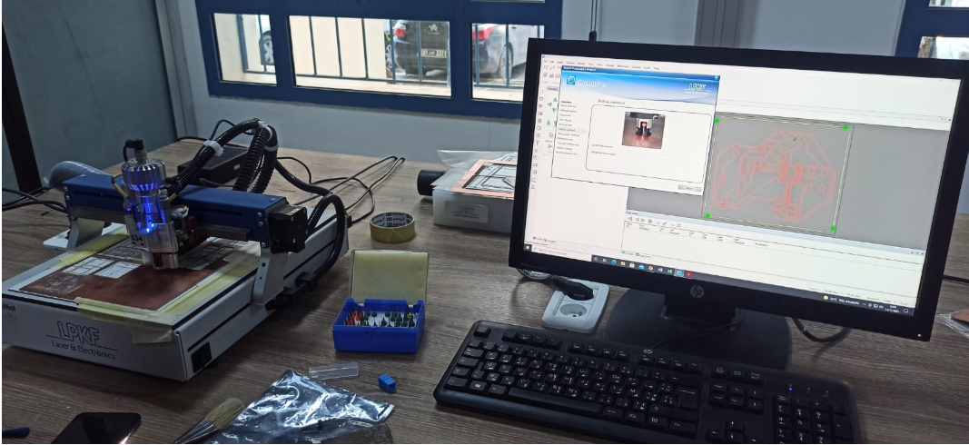
After that I used the LPKF the PCBs milling machine to produce my card :
The final step is to solder all the partes including the Atmega1284P:
Before all you need to select the appropriate microchip in arduino IDE as I explained the steps in my previous week10
Let’s start :
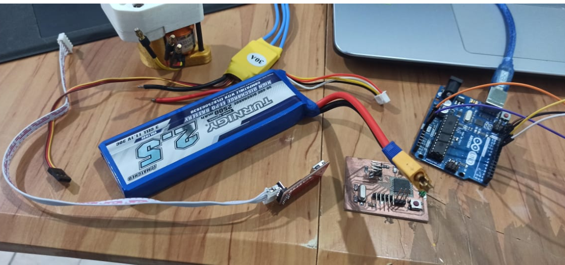
Prepare all the needed parts which are :
1- The brushless motor
2- ESC 30A
3- FTDI CABLE,ARDUINO and jumpers cables
4- The board
5- The lipo battery
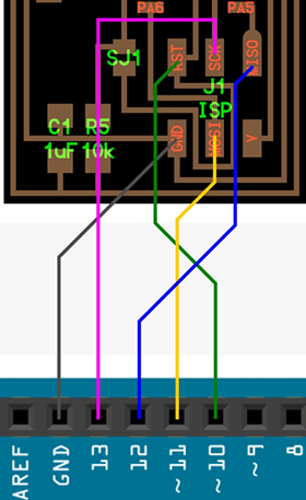
After connecting my card to arduino then to the laptop and selecting the appropriate microchip up in ARDUINO IDE - Tools - Mighty-1284p boards - avr-developers.com pinouts 16MHZ using optiboot and the programmer : arduino as ISP I burned the bootloader successfully.
Here are the suitable connections with the arduino
After I burned the bootloader I disconnected my board from the arduino then, I used the ftdi connection to link my board as it is shown below:
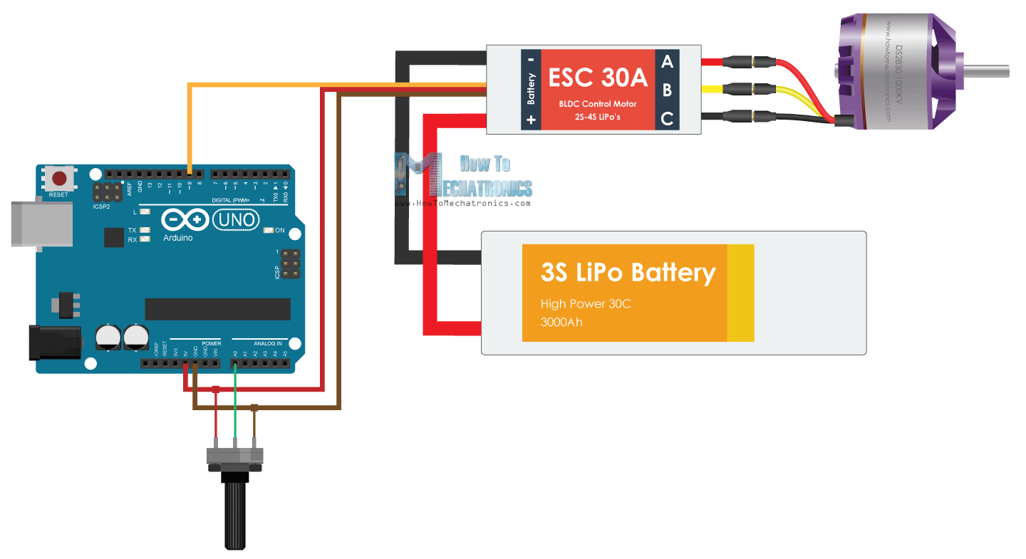
The other parts connections :
Below are the pins out of my ship (Atmega1284p):
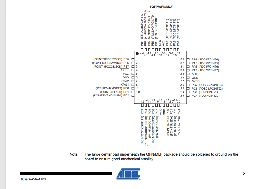
You can also check the ship datasheet from Here.
2- Connections :
ESC 30A with pin 13(PD4) of my board :
VCC with VCC
GND with GND
The brushless two ports :
- VCC with the lipo battery VCC
- GND with the lipo battery GND
After checking the connections I uploaded the code using the FTDI:
This is the right code :
//Parameters
const int escPin = 13;
int min_throttle = 1000;
int max_throttle = 2000;
unsigned long currentMillis, previousMillis;

void setup() {
  //Init Serial USB
  Serial.begin(9600);
  Serial.println(F("Initialize System"));
  //Init ESC
  pinMode(escPin, OUTPUT);
  initProcedure();
}

void loop() {
  runBrushless();
}

void runBrushless() { /* function runBrushless */
  //// Test Brushless routine
  Serial.println("running");
  currentMillis = 0;
  previousMillis = millis();
  while (currentMillis < 2000) {
    currentMillis = millis() - previousMillis;
    digitalWrite(escPin, HIGH);
    delayMicroseconds(1350);
    digitalWrite(escPin, LOW);
    delay(20);
  }
  Serial.println("stop");
  currentMillis = 0;
  previousMillis = millis();
  while (currentMillis < 2000) {
    currentMillis = millis() - previousMillis;
    digitalWrite(escPin, HIGH);
    delayMicroseconds(min_throttle);
    digitalWrite(escPin, LOW);
    delay(20);
  }
}

void initProcedure() { /* function initProcedure */
  //// ESC inittialisation process
  previousMillis = millis();
  Serial.println("throttle up");
  while (currentMillis < 3000) {
    currentMillis = millis() - previousMillis;
    Serial.println(currentMillis);
    digitalWrite(escPin, HIGH);
    delayMicroseconds(max_throttle);
    digitalWrite(escPin, LOW);
    delay(20);
  } //beep- beep-
  currentMillis = 0;
  previousMillis = millis();
  Serial.println("throttle down");
  while (currentMillis < 4500) {
    currentMillis = millis() - previousMillis;
    Serial.println(currentMillis);
    digitalWrite(escPin, HIGH);
    delayMicroseconds(min_throttle);
    digitalWrite(escPin, LOW);
    delay(20);
  } // beep--
  // 1 2 3
}
The work is done :