10. Input devices
This week I worked on defining my final project idea and started to getting used to the documentation process.
This weeks Assignment: 
-
Group assignment:
-
Probe an input device’s analog levels and digital signals
-
Individual assignment:
-
Measure something: add a sensor to a microcontroller board that you have designed and read it.
For this weeks group assignment you can check our page by clicking here
First part:(individual assignment): 
What does Input Device mean?
- it is a device / equipment (including sensors) used to provide data and control signals to an information processing system such as a computer , information appliance or micro controller . Examples of input devices include digital cameras, microphones sensors…
what does sensor mean?
- A sensor is a device, module, machine, or subsystem whose purpose is to detect events or changes in its environment and send the information to other electronics, frequently a computer processor. A sensor is always used with other electronics it responds to a physical stimulus (such as heat, light, sound, pressure, magnetism, or a particular motion) and responds to it in a distinctive manner.
For this weeks assignment I decided to use an ultrasonic sensor as an input device. As the name indicates, ultrasonic sensors measure distance by using ultrasonic waves. The sensor head emits an ultrasonic wave and receives the wave reflected back from the target. Ultrasonic Sensors measure the distance to the target by measuring the time between the emission and reception.

Using the arduino to work with the ultrasonic sensor:
Steps to do that :
1- link your arduino with the ulta sonic sensor using the jumper cables
-
VCC / VCC
-
GND / GND
-
Echo/ pin 10
-
Trig / pin 9

2- Now , connect the arduino to your laptop

3_ Open arduino software File/New and paste this code :
const int trigPin = 9;
const int echoPin = 10;

long duration;
int distance;
void setup() {
pinMode(trigPin, OUTPUT);
pinMode(echoPin, INPUT);
Serial.begin(9600);
}
void loop() {
// Clears the trigPin
digitalWrite(trigPin, LOW);
delayMicroseconds(2);

digitalWrite(trigPin, HIGH);
delayMicroseconds(10);
digitalWrite(trigPin, LOW);

duration = pulseIn(echoPin, HIGH);

distance= duration*0.034/2;

Serial.print("Distance: ");
Serial.println(distance);
}
4- Upload the code to your arduino .
5- AND IT WORKS ^^

I designed a new PCB for the INPUT DEVICE WEEK , I used the Atmega1284P as a microship and the folowing componants :
- 16 Mhz resonator
- Capacitors 1uF
- 2 resistors 10k and 499ohm
- 6 header Pins for programming(ISP)
- 5 headers pins connector for the ftdi (RX , TX , RESET , VCC AND GND )
- 4 headers pins for the ECHO , TRIG , VCC AND GND for the Ultrasonic sensor .
- 10uF capacitor
Here is the result after I linked all the parts together :


I used the LPKF PCBs milling machine to produce my Input electronic card :

After I milled my PCB, the next step is to solder it as it is shown in the image below :


Below are the pins out of my ship (Atmega1284p):
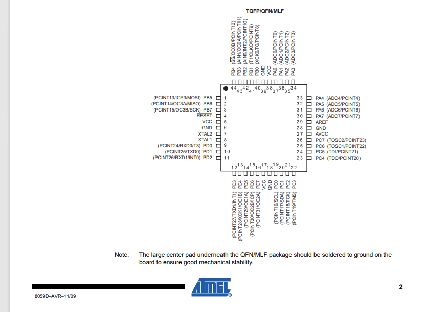
You can also check the ship datasheet from Here.
Steps to program the board :
Before all you need to add the suitable microchipe name in the arduino IDE as it is explained below :
1- Go to this site, click the Download ZIP button and save the ZIP file to a convenient location on your computer.
2- Ensure that the Arduino IDE is not running.
3- Go to your Arduino hardware folder.
4- Unzip the downloaded file into the hardware folder.
5- The download from GitHub will have a dash and branch name appended, so the folder will be named, e.g. mighty-1284p-v1.6.3. Rename the folder to just mighty-1284p.
7-The mighty-1284p compatible “official” patched libs are located to be used as default when a mighty-1284p board is selected in the Board menu by being in hardware\mighty-1284p\avr\libraries
8- Open again the Arduino IDE
9- select avr-developers.com pinouts 16MHz using Optiboot board
Now, you can use the appropriate microchip

The code:
#define echoPin 20 // attach pin D2 Arduino to pin Echo of HC-SR04
#define trigPin 21 //attach pin D3 Arduino to pin Trig of HC-SR04

// defines variables
long duration; // variable for the duration of sound wave travel
int distance; // variable for the distance measurement

void setup() {
  pinMode(trigPin, OUTPUT); // Sets the trigPin as an OUTPUT
  pinMode(echoPin, INPUT); // Sets the echoPin as an INPUT
  Serial.begin(9600); // // Serial Communication is starting with 9600 of baudrate speed
  Serial.println("Ultrasonic Sensor HC-SR04 Test"); // print some text in Serial Monitor
  Serial.println("with Atmega1284P);
}
void loop() {
  // Clears the trigPin condition
  digitalWrite(trigPin, LOW);
  delayMicroseconds(2);
  // Sets the trigPin HIGH (ACTIVE) for 10 microseconds
  digitalWrite(trigPin, HIGH);
  delayMicroseconds(10);
  digitalWrite(trigPin, LOW);
  // Reads the echoPin, returns the sound wave travel time in microseconds
  duration = pulseIn(echoPin, HIGH);
  // Calculating the distance
  distance = duration * 0.034 / 2; // Speed of sound wave divided by 2 (go and back)
  // Displays the distance on the Serial Monitor
  Serial.print("Distance: ");
  Serial.print(distance);
  Serial.println(" cm");
}
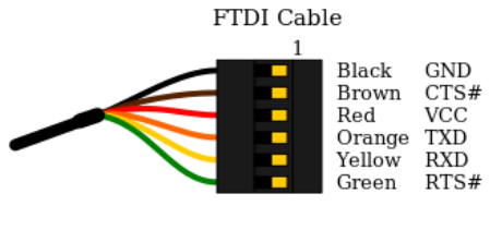
I used the Ftdi cable to link my board after I burned the bootloader using the AVRISP connections with the arduino
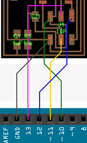
Here is the connections:

Trig with the pin 21
Echo with the pin 20
VCC with VCC
And GND with GND
The work is done^^