5. Electronics production
This week I worked on defining my final project idea and started to getting used to the documentation process.
This weeks Assignment: 
-
Group assignment:
-
Characterize the design rules for your PCB production process.
-
Individual assignment:
-
Make an in-circuit programmer by milling and stuffing the PCB.
-
Test it, then optionally try other PCB processes.
First part:(Group assignment): 
For this weeks group assignment you can check our page by clicking here
Second part:(Individual assignment): 
For this weeks assignment I made an in- circuit programmer (ISP) and programmed it , to do that I made 4 steps which were :
-
Downloading Brian’s ISP cutout(outline) and traces as a PNG formats.
-
Uploading the PNG files to Fabmodules to get the G-Code for the milling and cutting .
-
Soldring the ISP components and testing all it’s circuits.
-
Programming the ISP .
This were a general description of this weeks assignment steps.
Below are the PNG files from Brian.
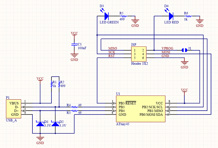
What is Fab ISP ?
Fab ISP allows us to program the microcontrollers on other boards we make, using nothing but a USB cable and 6-pin IDC to 6-pin IDC cable. It’s based on the USBtiny , which allow the ATtiny85 or 44 to perform USB communication in software. Programming can be done through avrdude.
- Let’s start:
To mill the ISP I used our fablab CNC and i linked the PCB with the double faces sticky :


## Generating G-Code for the ISP milling
1_ upload the traces PNG file to Fabmodules
a_ steps
- Image(PNG) / TRACES (png)

- Outline format / G-Code

- Process / PCB TRACES(1/64)

2_ Upload the outline PNG file as the traces steps before .But, the difference is that you need to select in the process window PCB outline as it shows below :

## Outline and traces parameters


- calculating G-Code after that you need to save it and After that you upload it to the CNC software.

- Now, you need to put your tools into the cnc and fixe the Z,Xand Y axes and start to mill your ISP.


- For me the first milling test was not good , so I tried to fixe the prob with my instructor but, after a couple of try we succeeded to fixe the issu .


_ The right result :


Now, you need to Peel off the extra copper from your ISP it should like this :


Soldring the ISP components:
-
To make your ISP soldring be good you need to follow this simple steps ;
-
Select carfully your ISP right components and thir right location like it shows below:


_ This is the right components location:


_ Below is the final result after soldring and cleaning the ISP from the extra wires :

- Note:
You should not solder the two half cercles before programming your board.
Programming
For me it was my first time to deal with programming , but, I am going to explain the steps in which I succeeded to programme my ISP.
1- You need to download the following softwares:
And
2_ You need to connect your arduino to your laptop after that do the following steps below:
a- Open arduino software.
b- Go to file/examples/arduino ISP after that there is a code will apear like it shows below:


c- Upload the code to your arduino to make it able to programme your ISP:

d- Disconnect your arduino from your laptop.
e- Now, You need to extract the Zip file which you downloaded before. Open the folder :

f- Click with the right button on * make file * and select/ open with Notepad :

g- You need to enter some modifications on the Notepad text instructions and commands :

h- Changing the commands on Notepad for git bash:
we need to do such a modification because the original text is made for the ISP and now we are using the arduino as a programmer for our Fabisp so we need to make it compatible for this final.
-
Commands and lines to change:
1- MCU: from attiny44 to attiny 85 .
2- Programmer ? from usbtiny to SK5001 **
 3- Now you need to change the port to the one in which your arduino is linked , for me is COM6 , so you need to change like the following:
4- file / save I- Before you Reconnect your arduino to your laptop you need to connect it using jumper cables with your ISP as it shows below:
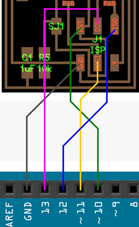

J- Now, connect only your arduino
k- Now, you need to reopen the same folder as before and right click on the mouse and select git bash here .
 1- you need to write some secial commands which are (LL) and (make) to verify that you are in the correct position and also to check the existance of two files which are fts_fireware.elf and fts_fireware.hex .

After you checked that you are in the right location and that the two files existed so you are in the right path , let’s continue ^^ .
L- Use the USB HUB, connect your arduino and your ISP to two ports and to your laptop


M- Go back to Git bash and carfuly write the following commands, because if you made a mistake with the order of each commande while you are typing them you will face problems as it happened to me ^^ in that case you will need to replace the microcontroller with another one new.
1- Make flash to send tje code to program the ISP
2- Make fuses to upload settings to your ISP .
3- Make rstdisbl to disable one of the pins to work as a reset


Once you see your ISP LED lights so, we can say you are 98% on the right path and your ISP programming is done.
N- Disconnect your arduino from the USB hub as well as all the jumper cables and keep only your ISP connected .

O- Now, we need to use the Zadig software to instal the driver for the ISP it will take some time but don’t worry every thing is fine ^^ .
1- Search for USPtinySPI
2- Click on Install Driver

P- Once the driver is installed, only now we can say you perfectly have done the job and your Fab ISP is programmed.. ^^
q- You can check that your ISP driver instaled by going to device manager /libusb- win32 devices and you find USBTINYSPI


Programming New ISP with my programmed fabISP:
-
To programm a new ISP using another you need to follow this steps as it shows below:
-
You dowwnload the same zip file as for the arduino and my ISP.
1- Extract it
2- open it’s folder
3- Right click with the mouse on MaKE file and select open with NOTEpad because we need to enter some modification also to the text but in this time we only need to change one ligne which is the type of the microcontroller from attiny44 to attiny85 .
MCU: from attiny44 to attiny 85
4- Save the modification.
5- Use the 6 pins isp cable to connect both Isps to the USB hub and then to the laptop.


6- Like before you need to open git bash in the extracted zip file folder and right the folowing commands.
make
ll
make flash
make fuses
make rstdisbl
7- Once the new ISP LED blinks the job is done and you don’t need to instal the driver for the new isp because it is already existed from the first fabisp programming .
