8. Computer controlled machining
This week I worked on defining my final project idea and started to getting used to the documentation process.
This weeks Assignment: 
-
Group assignment:
-
test runout, alignment, speeds, feeds, and toolpaths for your machine.
-
Individual assignment:
-
make (design+mill+assemble) something big.
Here is the link to The group assignment
Let’s start:
What is CNC Milling?
CNC milling, or computer numerical control milling, is a machining process which employs computerized controls and rotating multi-point cutting tools to progressively remove material from the workpiece and produce a custom-designed part or product. This process is suitable for machining a wide range of materials, such as:
-
Metal
-
Plastic
-
Glass
-
Wood
-
Titanium
-
Copper
-
Bronze
-
Zinc
-
PVC
-
Nylon and producing a variety of custom-designed parts and products.

Types of Milling Tools:
-
For each machine, you can find different sets of tools that perform different cuts. Some bigger, more industrial machines can even change the tool mid-job.
-
Different tools are designed for different materials, and it’s important to choose the perfect tool for the job. Failure to do so could result in unwanted damage to the material, the tool, or both.
-
Let’s compare wood and steel: If you choose an overly strong steel tool to cut wood, you could end up losing the workpiece. Meanwhile, if you use wood tools for steel, you will certainly end up breaking the tool and the machine.
-
As stated earlier, the most basic tool is a milling cutter, which kind of resembles a drill bit, but with teeth designed to remove material in ways other than just drilling. Cutters can vary in shape and size as well as in teeth orientation and spacing.
Cutting Parameters for CNC Machine:
-
Right cutting parameters produces a precise output, which helps in reducing cycle times, and machine costs. The speed and motion of the cutting tool are specified through several parameters that can be modified for different operations based upon the workpiece material and tool size.
-
If the cutting speed is too fast, the cutting time can be shortened, but the cutting tool is easy to generate high heat, which affects the service life of the cutting tool. Therefore, ensuring cutting speed is the most important thing in our work.
-
Cutting speed: This criterion measures the number of feet the tool passes over the surface of the work piece per minute in Surface Feet per Minute (SFM). The material and the process often decide the cutting speed. For example, grooving requires slower cutting speed for accurate results.
-
Cutting Feed This parameter measures the distance undertaken by the cutting tool for every single revolution. It is measured in Inches per Revolution (IPR). Depending upon the mode of operation, the tool is either fed into the workpiece or the workpiece is fed into the tool.
-
Spindle Speed: The spindle speed is obtained when the cutting speed is divided by the circumference of the work piece in Revolutions per Minute (R.P.M). The speed varies depending upon several factors like the diameter of the cut or the surface area.
-
Feed Rate: It is defined as the speed of the cutting tool when it cuts through the material. It is the product of the cutting and spindle speed measured in Inches per Minute (IPM).
-
Axial Depth of Cut: This parameter measures the depth of a tool as it cuts towards the axis of the material. A large axial depth of cut is needed to overcome the high load on the tool.
-
Radial Depth of the Cut: This parameter measures the depth of the tool as it cuts along the radius of the material. To enhance the quality of the cutting tool, a lower feed rate is needed.
Endmill


For further information about CNC_MillingToolsAndTheirApplication DATA sheet you can press this Link.
For this week group assignment you can check our page by clicking here
Make somthing Big:
Honestly, this is my first time working with this big version of CNC milling machine and it’s the first week of the the quarantine in Tunisia after the outbreak of COVID-19! Most of things are closed, the FABLABs were closed too! So for now I only made the design on Fusion 360
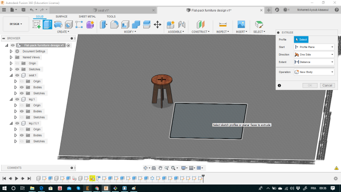
Design using a CAD program
For this step I used Fusion 360 to make a * wooden stool seat *:
Steps:
I started with the seat (I made it in the shape of a circle). Then I extruded it to 1.92mm


As for the leg, I started doing the outlines for the left half!!


Then with a click on “Mirror” I made the other right half!

Now it’s ready to be extruded:

And now for the other sit of leg: COPY & PASTE

For these legs to be fixed into each other, I made so paralleled “holes” to fix them!

And to fix these legs into the seat, I needed to make holes on it !


Below are the parameters I used to design:


Dogbones:
After I finished my design, I designed the dogbones for all the shape corners, This method lets the part sliding into this corner just barely ‘kiss’ the inside of the circle, which is good for joints that take stress because the corner is still supportive.
_ I create a rectangle with the same size of the end mill that I am going to use.


_ I used the mirror and the circular pattern tools to clone the circle in every corner:

_ I extruded them as it is shown below;


_ And this is it The shape will look like it shown below


And Below is my final result:

To prepere the design for cutting I need to do these steps:
_ Create a rectangle and extrude it with like it is shown below:

Now , use the align tool to place the stool parts on the rectangle


And this is it, your design is ready:

Now, we need to prepare the cutting parameters:
1- You need to sellect Manufacture on the top left of your fusion program as it shown below:

2- Go to seteps in the left , and with right click on it, press new setep and adjust your axes (x,y and z), edit your machine name and select the operation type as Milling :

3- The next step will be selecting the setups for cutting and drilling , for that you need to go at first drilling and select drill , a window will apear:
a- Select: tool edit and ajust the needed one as it shown below :

b- For my case I chose to drill the dogbones for a good result, for that you need to select the dogbones in each face as it presented below :

4- Now , you need to select the second setup which is 2D Contour : for that you need to go 2D and chose the right option :
a- Select the right tool :

b- Select the right contours and highlight the tab option to hold the cutted parts from moving as it is presented below :

5- After you finish setting up the parameters for your design, you need to prepare the G-code to start the cutting process on your CNC, below are the two simple steps to generate the G-Code :
a- Right click on setup9 (it combine both drilling and contouring setups ) and press Post Process as it shown below :

b- A window will apear , select the right extension which is .nc and then Post :

6- Your G-Code is ready now to upload on your CNC machine to start the job , below are a different images to show the work process:


The job is perfectly done ^^

How tabes looks like :

After removing the parts:

Assembling all the parts together:

The small chair is confortable to sit ^^ :
