Group Assignment: Computer-Controlled_Machining
test runout, alignment, speeds, feeds, and toolpaths for your machine
test runout, alignment, speeds, feeds, and toolpaths for your machine
The “Make Something Big” assignment happened right around the time our labs were being shut down for the pandemic, so it wasn’t really possible to get the everyone together to do the group assignment, which was a bit of a bummer. However, since we ended up spread out across several home and uni labs, we instead have the opportunity to explore the capabilities of several different machines.
Kleve: CNC-Step High-Z S-1400-T
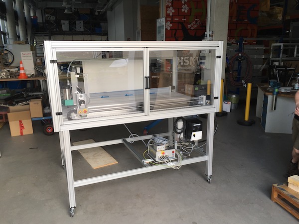
This machine was delivered to the ENSPIRE lab in Kleve shortly after the shutdown. With a working space on the bed of 1400 x 800mm and a z-axis range of 110mm above the aluminum bed (which is removable to make even more clearance if necessary), our machine is equipped with a 2.5kW router head and housed in a plexiglass safety cage.
Set up
The set up of the machine was straightforward - basically just involved plugging all of the various cables into the right ports as per the user’s manual. We had to make a wall cord, as none was supplied with the machine, and its pins were turned 90° to the usual computer/fridge power cable set-up. Lots of electric tape minimised any associated risk of electrocution…
The machine is controlled live from a PC using a software package called KinetiC-NC. There is a remote control, but that proved impossible to install with the limited instructions, so we left it for now.
There were a couple of modifications that had to be set in the configuration section of the program, so that the machine would recognise the spindle and so that it would respond to the door opening properly (safety shut down). I found later that the default safety shut-down made lining up the machine near on impossible, but the engineers had thought of that and provide an option in the configuration to allow slow movement of the gantry while the doors are open.
The machine has an automatic magnetic z-axis calibration system, but a bad glue joint on that broke very quickly in the first week, which rendered it useless (lots of manufacturing quality letdowns on this machine. I suppose there are always teething problems with new machines, but we’ve had more than I’m used to with this one - more on that later.) Calibration of the z-axis then relied on the tried-and-true squish a piece of paper between the workpiece and the milling bit.
After firing up the machine for the first time and proving we could drive it with the arrows on the control panel, we tried some initial “cut air” g-code tests. Here’s where we fell down badly. After random periods of time, the z-axis would refuse to go up, and the machine would continue merrily on its highspeed traverse with the tool essentially still engaged in the (virtual) workpiece. Then on the next cut, it would start in z where it had go to, rather than at the safe height, so that if there had been a tool in the spindle, it would have drilled right through the bed (that is, if it had survived the traverse!).
The problem took two weeks to diagnose, with back-and-forths with the manufacturer. We changed the speeds, replaced the power cord, checked all of the connections, looked for hot PC boards and/or jammed motors, and bought a new computer, only to discover that the problem was a bad set of crimp connections in a junction box by the z-motor. Once I’d crimped those properly, the machine was finally reliably ready to run (or at least, so we hope.)
FabTesting the Machine
Our group assignment consists of four tests. We’re to measure the runout, which is the “wobble” in the milling bit, check the alignment, and verify the speeds, feeds and toolpaths of the machine.
Runout
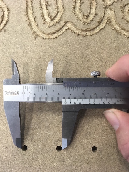
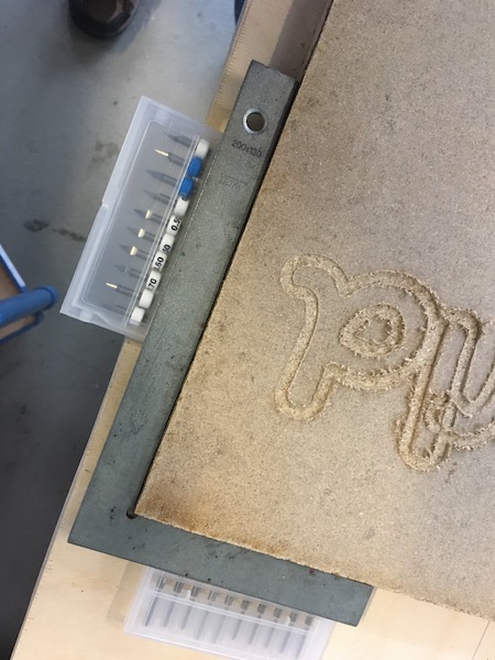
To measure the runout, we cut a set of holes 3.0 cm apart in a piece of MDF with a 5mm milling tool and measured their diameter with steel caliper. As the machine is brand new, and the cutter was short, there is nothing exciting to report. The holes were exactly 5.0mm in diameter. This is shown in the left hand pic below. As a further test, we measured the distance from the left hand side of one hole to the right hand side of the next, and found a slight deviation of 0.1mm. Whether that is real or a function of the precision of the placement of the measuring device is hard to say. The measurement is shown in the right hand pic below.
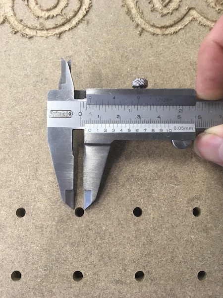
Suffice it to say, the new machine doesn’t exhibit much runout.
Alignment
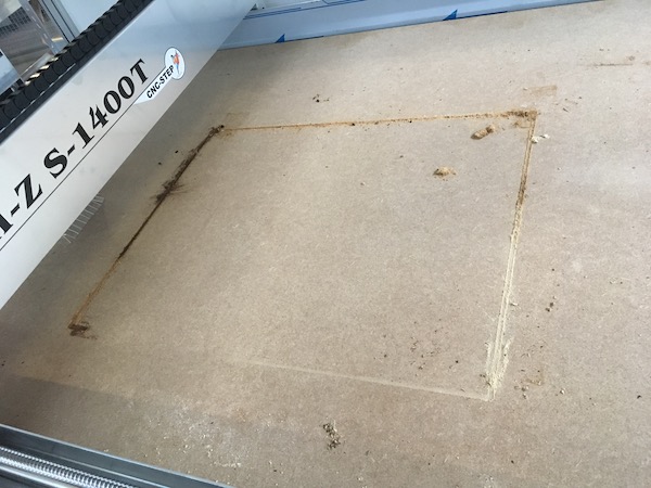
To check the alignment, we cut out a square part and verified that the corner was indeed 90° using a metal square.
Speeds & Feeds
To test the speeds, we used the Fablab Speed and Feeds Calculator. There one can input the tool diameter (6mm - 0.236”) and number of flutes (4), plus some standard information about the material being cut. In the case of this test, we were using 18mm thick OSB, carpet taped to a 20mm piece of MDF. The calculator suggests we should use a surface speed of 650 ft/min and a chip load of about 0.010”. Putting those numbers into the calculator produced some first estimates of machining speeds: spindle 10520 RPM, 421”/min (ca 11m/min) feed rate and 210.5”/min (5.3m/min) plunge rate.
The machine is limited to maximum 7500 RPM on the spindle and 750mm/min feed-rate. The order of magnitude difference between the machine capability and the recommended cutting speeds is a little disconcerting, to say the least. We decided to eyeball the test instead.
A quick test pattern was drawn up in Fusion 360:
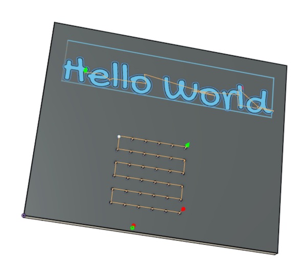
Not really giving it much thought (sleepwalking into disaster), we just relied on Fusion 360’s Drilling and 2D Contour strategies and used the postprocessor to create the g-code. KinetiC-NC couldn’t read the files produced, so we copied and pasted the contents of the file into a dummy file created with KinetiC-NC and that seemed to work fine (at least when cutting air).
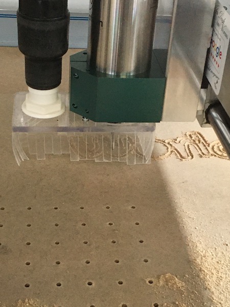
At first we chose spindle speed of 5000RPM and drilled a 6x6 hole pattern. That went well. After a few holes, we ramped the spindle up to 7500RPM and all seemed good. The sound was right, though there was some squeaking on the retraction - we put that down to the board deforming on pull-out, as we hadn’t taped it down well enough.
When the drill pattern was done, the machine started on to milling out the “Hello World”, which it did very nicely, though not as deeply as I thought I had programmed it to do.
The real trouble began when the machine started to cut out the surround. Here’s where not paying attention can get you into trouble. The Fusion360 cutting algorithm went straight to an 18mm deep cut, which was exactly the length of the flutes on the milling bit. It took off at 300mm/min, and for the first 15cm did just fine. Then the flutes began to clog up as the vacuum fitted to the milling head was unable to suck out the sawdust. Then the machine started to stall, so we slowed down the feed rate to 215mm/min. That seemed to be ok, though it was obvious that the sawdust was getting too hot.
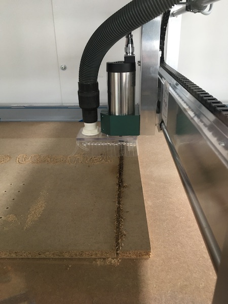
When the machine turned the corner and cut along the back stretch, we started really to notice the burning. The vacuum cleaner extractor did a pretty good job of sucking out the smoke, but it was obvious that the mill was basically burning its way through the wood, rather than cutting. We slowed it down some more, but that just made it worse, so we sped back up again to find a compromise where the burning stopped. That we found at around 240mm/min.
Then the machine turned the final corner. This is where it really went sour. The milling bit was by this time completely covered in melted glue and the vacuum really wasn’t sucking any sawdust away. The machine stalled once, so we slowed it down, which made the burning worse. Then the glue of the carpet tape gave way and the part came loose, at which point we hit the emergency stop.
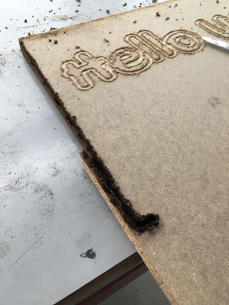
Closer inspection after the smoke and dust cleared revealed what had gone wrong. It should have been obvious from the start that the cut was too deep (and in retrospect, it was), so we should have stopped right away and edited the g-code. From the picture above it is obvious that only the top layer of the cut was burning. What happened was that the flukes weren’t long enough, and so the sawdust built up in that narrow space where essentially the tool was oozing its way through the material. Below the burn marks, the cut is clean and unburnt, suggesting that the speed there was fine, had it been possible to get the sawdust away. The evidence in the sacrificial layer below the cut, however seems to suggest otherwise (though this is after the board had been removed, and the burnt dust evident in the return path to the left may have fallen into place after the cut.)