9. Embedded programming
This weeks Assignment: 
-
individual assignment:
-
Read a microcontroller data sheet.
-
Program your board to do something,with as many different programming languages and programming environments as possible.
-
-
Group assignment:
- Compare the performance and development workflows for other architectures.
For this weeks group assignment you can check our page by clicking here
First part:(individual assignment): 
It is my first time to deal with all this stuff embedded programming, the Arduino Microcontroller and the datasheets … I was so excited to discover new things.
_ Let’s start::
What are Datasheets:
-
They are instruction manuals for electronic components. They (hopefully) explain exactly what a component does and how to use it. Unfortunately these documents are usually written by engineers for other engineers, and as such they can often be difficult to read, especially for newcomers. Nevertheless, datasheets are still the best place to find the details you need to design a circuit or get one working.
-
A datasheet is usually used for commercial or technical communication to describe the characteristics of an item or product. It can be published by the manufacturer to help people choose products or to help use the products. By contrast, a technical specification is an explicit set of requirements to be satisfied by a material, product, or service.
Here is the link to undrestand how to read a datasheet.
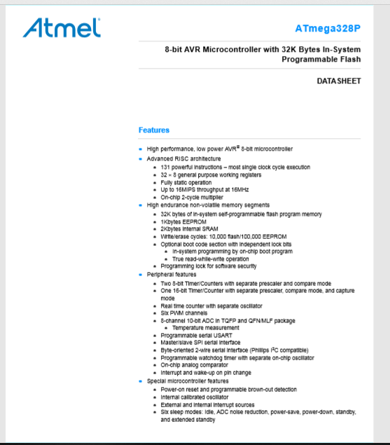
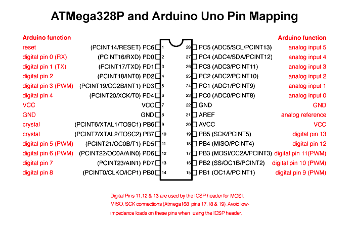
For this weeks assignment , I used the ATmega328P microcontroller.
This is the link to the ATmega328P Datasheet.PDF
-
ATMEGA328P is high performance, low power controller from Microchip. ATMEGA328P is an 8-bit microcontroller based on AVR RISC architecture. It is the most popular of all AVR controllers as it is used in ARDUINO boards.
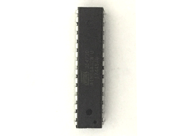
-
ATmega328P is one of the high performances AVR technology microcontroller with a large number of pins and features. It is designed by 8-bit CMOS technology and RSIC CPU which enhance its performance and its power efficiency get improved by auto sleeps and internal temperature sensor. This ATmega328P IC comes with internal protections and multiple programming methods which helps the engineers to priorities this controller for different situations. The IC allows multiple modern era communications methods for other modules and microcontrollers itself, which is why the microcontroller ATmega328P usage has been increasing every day.
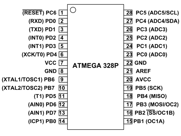
Pin Mapping of ATmega328P with Arduino;
- ATmega328 comes in Arduino, which helps the users to code the program in Arduino instead of assembly or other controller languages. Arduino is popular because of its vast online data and high-level language, and this helps the developer to code the controller program in Arduino and them convert it into the microcontroller code. In case of Arduino the pin configuration for the controller will be the following:
* Parametrics:
-
Program Memory Type: Flash
-
Program Memory Size (KB): 32
-
CPU Speed (MIPS/DMIPS): 20
-
SRAM (B): 2,048
-
Data EEPROM/HEF (bytes): 1024
-
Digital Communication Peripherals: 1-UART, 2-SPI, 1-I2C
-
Capture/Compare/PWM Peripherals: 1 Input Capture, 1 CCP, 6PWM
-
Timers: 2 x 8-bit, 1 x 16-bit
-
Number of Comparators: 1
-
Temperature Range (°C): -40 to 85
-
Operating Voltage Range (V): 1.8 to 5.5
-
Pin Count: 32
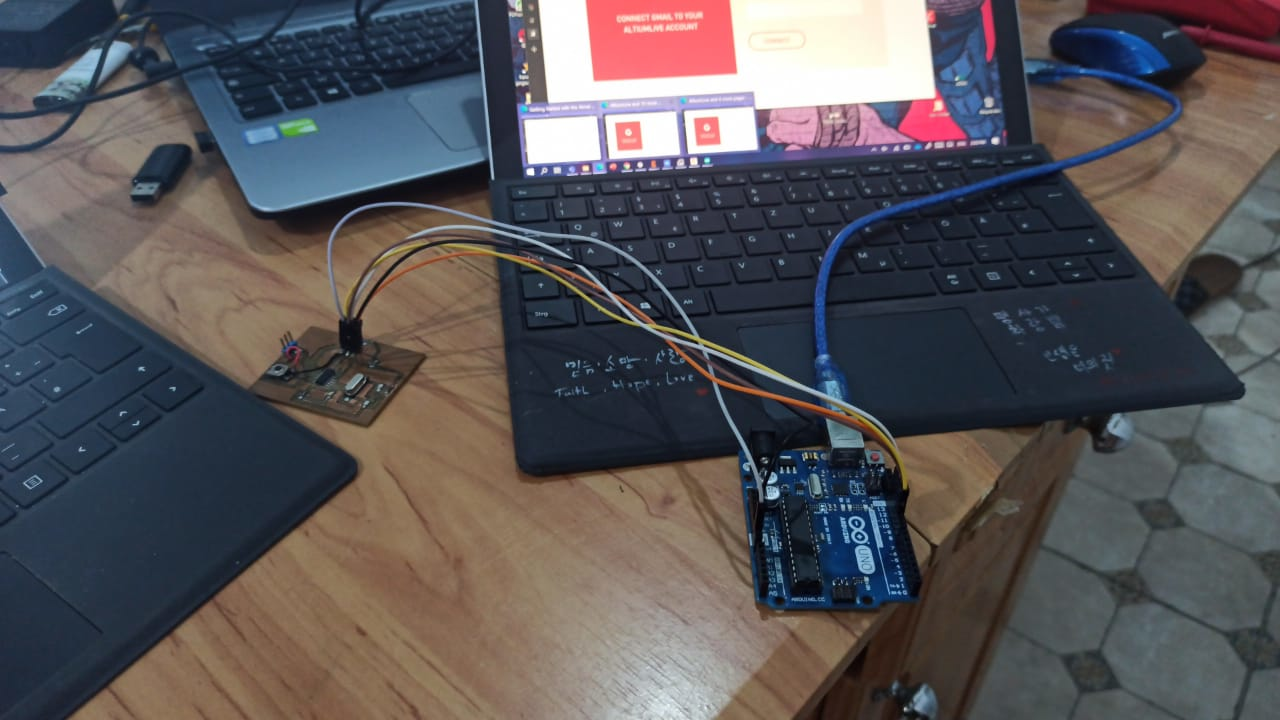
Arduino UNO R3
Since we didn’t succeed to make our PCBs for the 4th and 6th Week due to the lack of materials, we decided that we’re going to work with the ARDUINO itself:
However we got into a new problem: The total country’s lockdown due to the spread of COVID-19
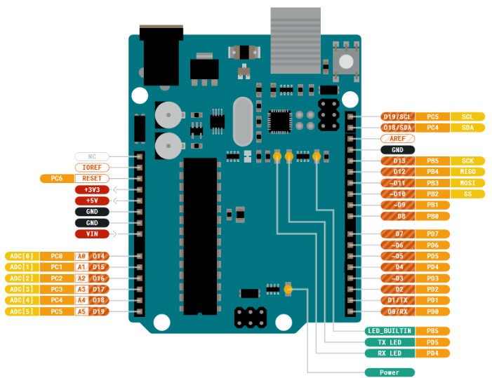
- Arduino is used for building different types of electronic circuits easily using of both a physical programmable circuit board usually microcontroller and piece of code running on computer with USB connection between the computer and Arduino.
So let’s get started
All what you have to do is downloading its software from Here.
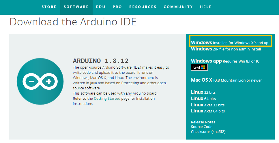
Programming language used in Arduino is just a simplified version of C++ that can easily replace thousands of wires with words.
Since I’m only using the online Simulation, I didn’t really make a big deal of the whole procedure for now
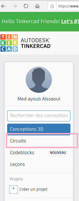
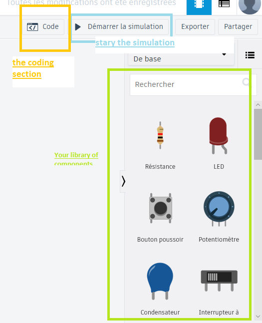
For the online Simulation, I used the TinkerCAD.
TinkerCAD is a free online software from Autodesc and a collection of software tools that a very useful to be used. Here you can simulate whatever circuit you want:
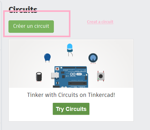
And with the help of of a library you can choose the component that you want to use and see how things are going to work
And this is what I made
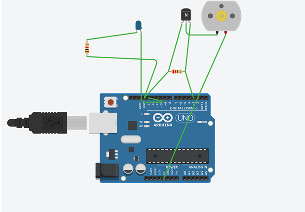
I only used the C++ language ,
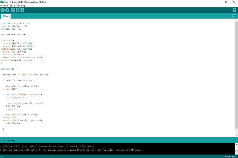
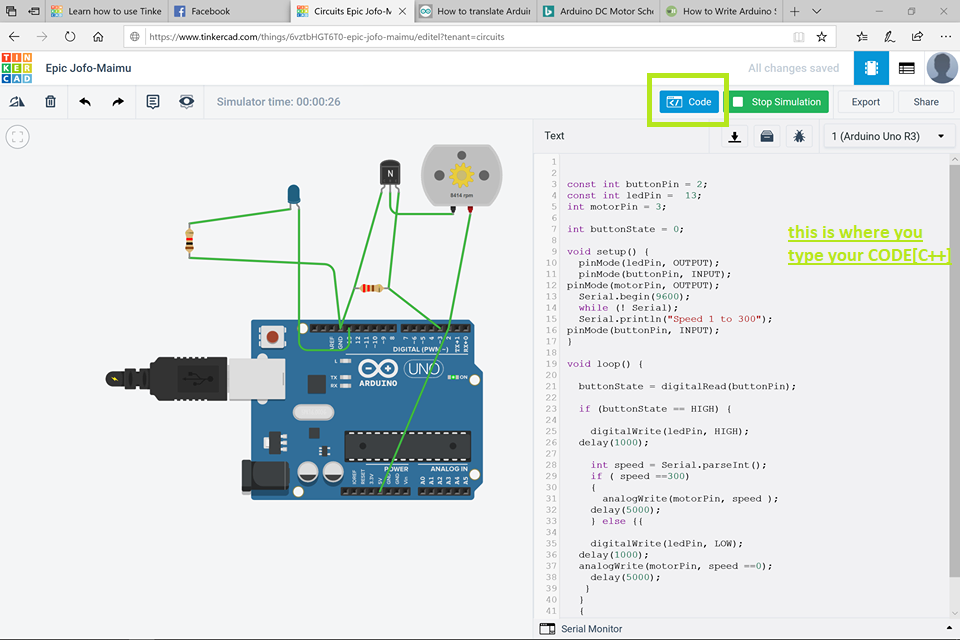
Below is the result when I pressed the red button (the Led pin is low and the DC motor stop then continues to work).
I used my Hello board from Week7 to program it next I tried to explain more about the microchip I used:
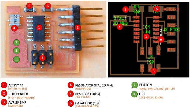
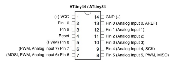
Here you can find the Datasheet of the Attiny44
To succeed in programming the Attiny44 using the Arduino IDE you need to select the right microchip withe appropriate crystal value which is 16MHZ with the right connections as it explained in detail in my 7th week
There was an important issue I faced during programming my board which was when I tried to use the servo Motor it doesn’t work despite, I used different codes but, without results.
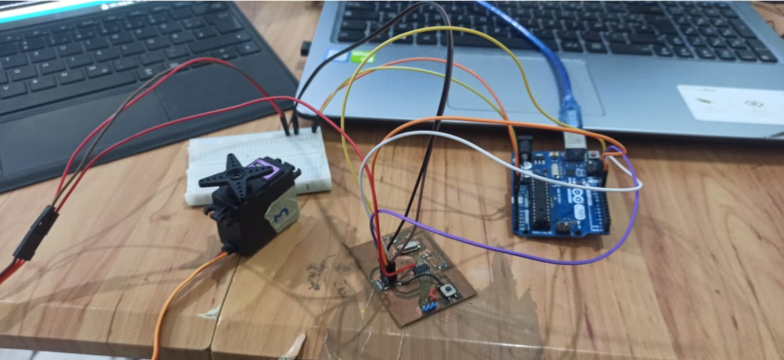
This was why I used to blink the LED with the push button
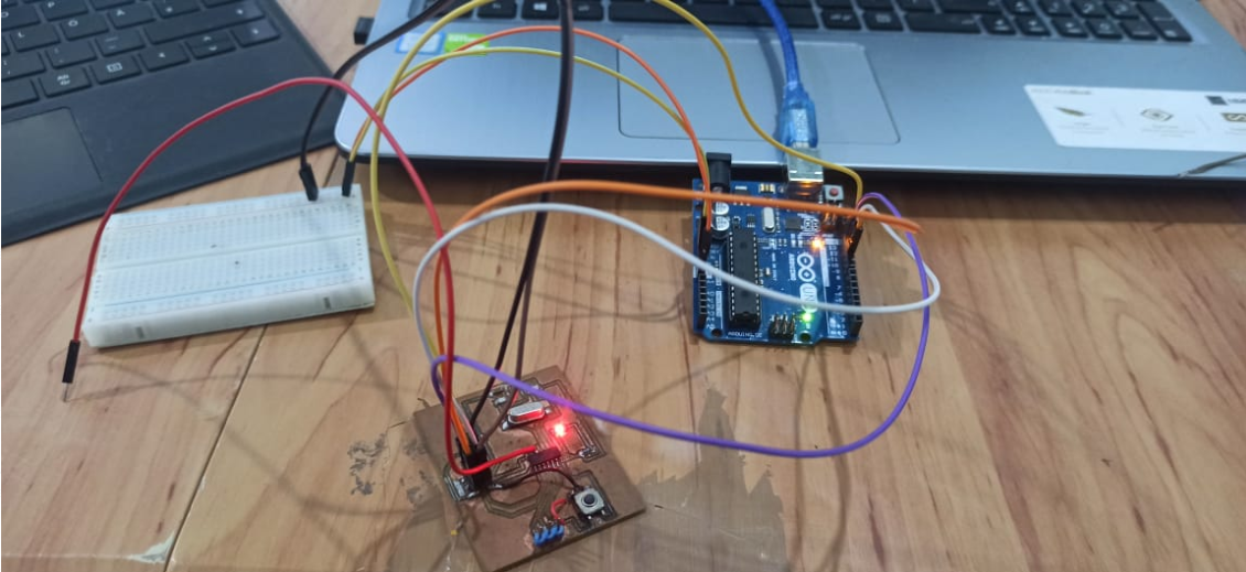
Here is the arduino code I used :
const int BUTTON = A1;
const int LED = 7;
int BUTTONstate = 0;

void setup()
{
  pinMode(BUTTON, INPUT);
  pinMode(LED, OUTPUT);
}

void loop()
{
  BUTTONstate = digitalRead(BUTTON);
  if (BUTTONstate == HIGH)
  {
    digitalWrite(LED, HIGH);
  }
  else{
    digitalWrite(LED, LOW);
  }
}
C Code (LED blinking)
what is C language ?
- The C programming language is a computer programming language that was developed to do system programming for the operating system UNIX and is an imperative programming language.
Input/Output :
-
There are 3 registers that control the I/O pins: DDR, PORT and PIN.
-
Each port has its own registers. Hence, port A has registers DDRA, PORTA, PINA;port B has registers DDRB, PORTB, PINB; and so on.
-
DDR, PORT and PIN serve different functions.
DDR (Data Direction Register):
-
DDR decides whether the pins of a port are input pins or output pins.
-
If the pin is input, then the voltage at that pin is undecided until an external voltage is applied.
-
If the pin is output, then the voltage at that pin is fixed to a particular value (5V or 0).
-
Port :
-
The bits on the PORT register correspond to the pins of the associated port it is the same case for DDR register.
-
it is used to set the output value.
-
It gives the value of the actual voltage at a particular pin.
-
I used my Hello board to blink it’s LED using the C programming so for more details about the ship , the board and how to link it with the arduino to upload the code you can check my 7th week electronics design .
-
I used this c programming code :
1- #include avr/io.h
- Include header file to tell the chip where all the ports and pins are located.
2- #include util/delay.h
- Include header file to use built in delay features for accurate delay.
3- DDRA = (1 << PA7)
- set PA7 to be output - connect your LED to pin 7
4- PORTA = (1 << PA7)
- set PA7 high
5- PORTA &= ~(1 << PA7)
- set PA7 low
6- delay_ms(1000)
- delay 1 sec
#include <avr/io.h>
#include <util/delay.h>
#define F_CPU 8000000
int main (void)
{
// set PA7 to be output - connect your LED to pin 7
DDRA = (1 << PA7);

// loop
while (1) {

// set PA7 high
PORTA = (1 << PA7);

_delay_ms(1000);

 // set PA7 low
PORTA &= ~(1 << PA7);

_delay_ms(1000);
 }

 return 1;
}
- Here is how I uploaded the code and how it worked :