Robot - Electronic design
lets start:
Electronic design: 
For my final project board , I used the Autodesk eagle , and below are the componants :
-
Microcontroller : Atmega 1284P
-
voltage regulator: 3.3V
-
SMD clock : 16MHZ crystal
-
AVRISPSMD : For Programming
-
pinheader for VCCs and GNDs
-
Ultrasonic sensor pin headers : 4 pins
-
Buzzer pin headers : 3 pins
-
Nrf24 pin headers 8 pins
-
FTDI : 5 pins
Due to some conditions in the instability of the NRF24 while trying to program my card, I was obliged to enter some changer into my board. I changed the NRF24 to the HC-12.
Schematic: 

Board: 

Manufacturing : 
I face a lot of troubles using my fablab cnc machine, the quality was too bad despide, I tried to do it many times but without a good result For that I seeked for another PCBs milling machine in another fablab, I found a good one which was the LPKF for pcbs and I used in my board manufacturing .
As a first stepo I used , I generated a cam data for my board to use it with the machine software as it is shown below :


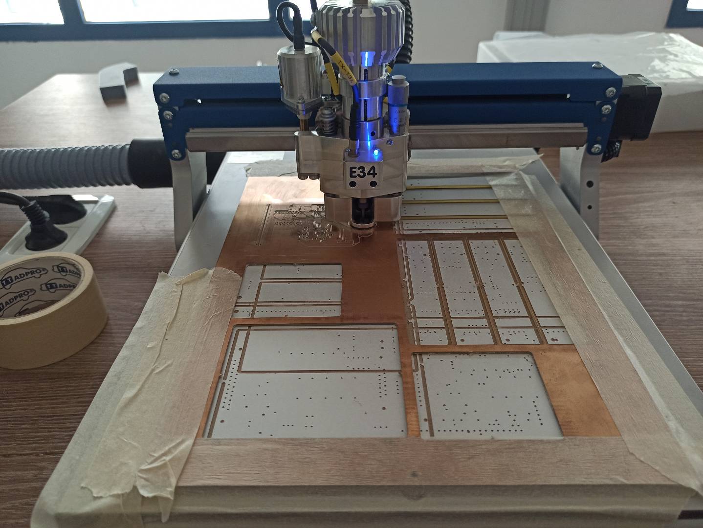

Here is the final result I got :


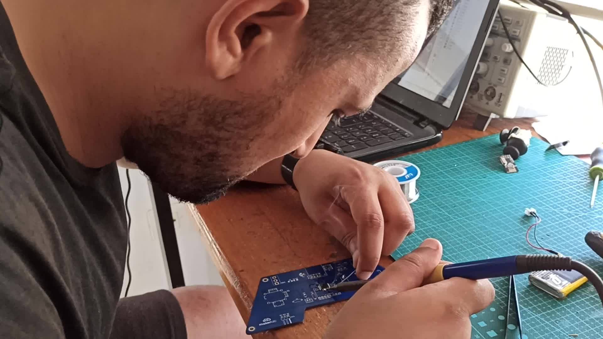
Soldring : 
I loved soldring , and through fabacademy I upgraded my level in it , that’s why I bought a soldring station to solder at home : here are the diffrent steps I went through :
Below is the list of the componants I used in my board:
- 16 Mhz resonator
- 1 Capacitor 1uF
- 2 capacitors 10 uF
- 2 20 pF and 100 nF capacitors
- 2 resistors 10k and 499ohm
- 6 header Pins for programming(ISP)
- 5 headers pins connector for the ftdi (RX , TX , RESET , VCC AND GND )
- 3 headers pins for the ESC 30A of the brushless motor
- 4 headers pins for the ultrasonic sensor(ECHO TRIG GND AND VCC)
- 3 headers pins for the Buzzer sensor
- 8 headers pins for the NRF24
- 3 HEADERS PINS FOR THE 3.3V VOLTAGE REGULATOR
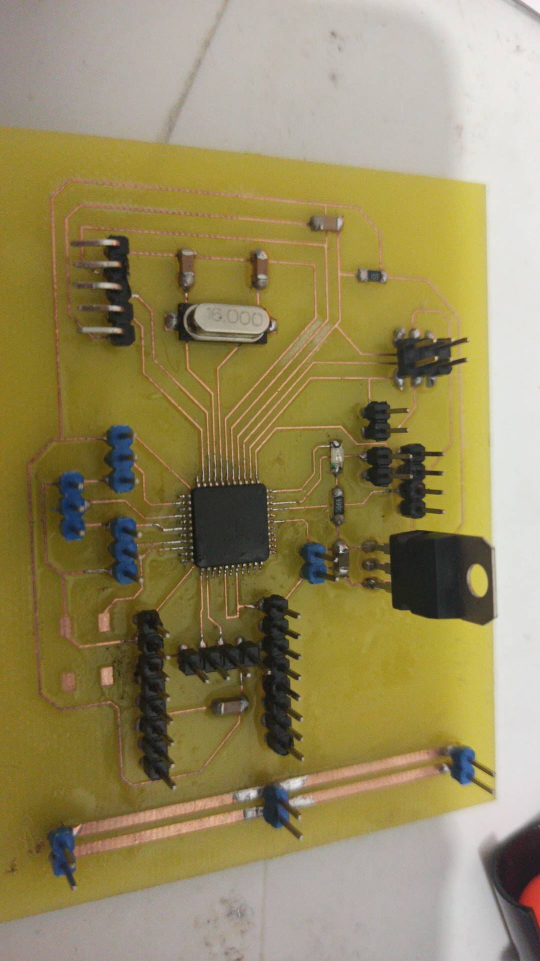
The Atmega1284p soldring :


The other componantes soldring:


Here I the final result I got :

I was too happy because of the level I arrived, after I the soldring mission finished , It was time for programming and to verify if everything was good , I used the Arduino as ISP to burn the bootloader and I uploaded a simple code of LED blinking to my board formore convinsing .
I used the satshakit schematic to read the pins numbers :

Before doing anything, I needed to finx the arduino IDE and uploaded the right micro controller name to success in burning the microship bootloader and here are the steps I used :
1- Go to this site, click the Download ZIP button and save the ZIP file to a convenient location on your computer.
2- Ensure that the Arduino IDE is not running.
3- Go to your Arduino hardware folder.
4- Unzip the downloaded file into the hardware folder.
5- The download from GitHub will have a dash and branch name appended, so the folder will be named, e.g. mighty-1284p-v1.6.3. Rename the folder to just mighty-1284p.
7-The mighty-1284p compatible “official” patched libs are located to be used as default when a mighty-1284p board is selected in the Board menu by being in hardware\mighty-1284p\avr\libraries
8- Open again the Arduino IDE
9- select avr-developers.com pinouts 16MHz using Optiboot board
Now, you can use the appropriate microchip

for More detail you can check satshakit Github
After doing all the previous steps , I burned the bootloader with the arduino ISP connectors and I uploaded the led code using the FTDI :


After I checked that everything was good and my board was working perfectly , It’s time now to check the card different parts , I meant the output device and the input devices :
The ultrasonic sensor checking:
Brushless motor checking:
For the buzzer sensor I added in further step
After every sensor was working perfectly its time for having a look on the remote controller I used :
After days of thinking, I choose to use my friend ANIS TRIGI new remote controller in stand of a prepared one , which he designed with his team mate , the group was working under the name of a new startup called Maker lab, he gave me the chance to solder it myself and the chance to give me a pdf for the remote controller schematic: