7. Electronics design
This week I worked on defining my final project idea and started to getting used to the documentation process.
This weeks Assignment: 
-
Group assignment:
-
Use the test equipment in your lab to observe the operation of a microcontroller circuit board.
-
Individual assignment:
-
Redraw an echo hello-world board.
-
Add (at least) a button and LED (with current-limiting resistor).
-
Check the design rules, make it, and test it.
-
Extra credit: simulate its operation.
First part:(Group assignment): 
I started by defining an important equipment in our fablab which is Multimeter .
What does Multimeter mean?
    A multimeter is an electronic tool used to measure voltage, amps and resistance across circuits.By attaching two leads to different parts of an electrical system, professionals can use multimeters to detect levels of voltage and resistance, or changes in electrical currents.

    This tool may also be known as a volt-ohm meter or volt-ohm-milliammeter (VOM).

    Multimeters can be valuable troubleshooting tools when working with circuit boards. Even if you don't have an electrical schematic of the circuit board, which would identify components and give you the voltage and resistor values that should be present, many circuit boards have test points that are clearly labeled. Use a multimeter on these test points to see if the voltage measured matches the labeled test point voltage. If they are the same, it will give you confidence that the circuit board is operating normally.

Components of a Multimeter:
-Multimeters are made up by four essential sections:
Display: this is exactly where the dimensions are shown

  Selection Knob: this picks what you desire to measure

     Ports: this is where you plug in the probes

        Probes: a multimeter comes with two probes. Typically, one is red as well as the various other is black.

Check Continuity:
If there is very low resistance between 2 points, which is less than a few ohms, both points are electrically attached and you’ll listen to a constant noise. If the noise isn’t continuous or if you do not listen to any kind of sound in all, it means that what you’re testing has a malfunctioning link or isn’t connected in any way.
-
A continuity examination tells us whether two things are electrically linked: if something is continual, an electrical current can flow freely from one end to the other.
-
If there’s no continuity, it indicates there is a break somewhere in the circuit. This can suggest anything from a blown fuse or poor solder joint to an improperly wired circuit.

For this weeks group assignment you can check our page by clicking here
Second part:(individual assignment): 
Echo hello-world board
It was my first time to design a board, but it was an enjoyable experience.
At first, I downloaded Autodesk Eagle ( educational version) which is an electronic design automation (EDA) software. Enabling printed circuit board (PCB) designers to seamlessly connect schematic diagrams, component placement, PCB routing, and comprehensive library content..

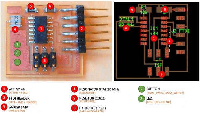
I used this components for the hello board:
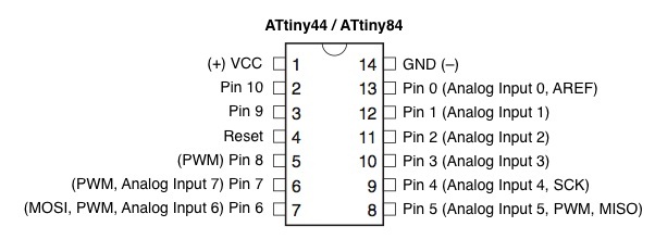
- AtTiny84 microcontroller
- 20 Mhz resonator
- Capacitors 1uF
- 2 resistors 10kohms
- 6 header Pins for programming(ISP)
- FTDI connector
What I added: * A LED * A 499 Resistor * A push button
STEPS TO DESIGN:
It was my first time to use Autodesk Eagle Software.
1- I opened eagle _new project:

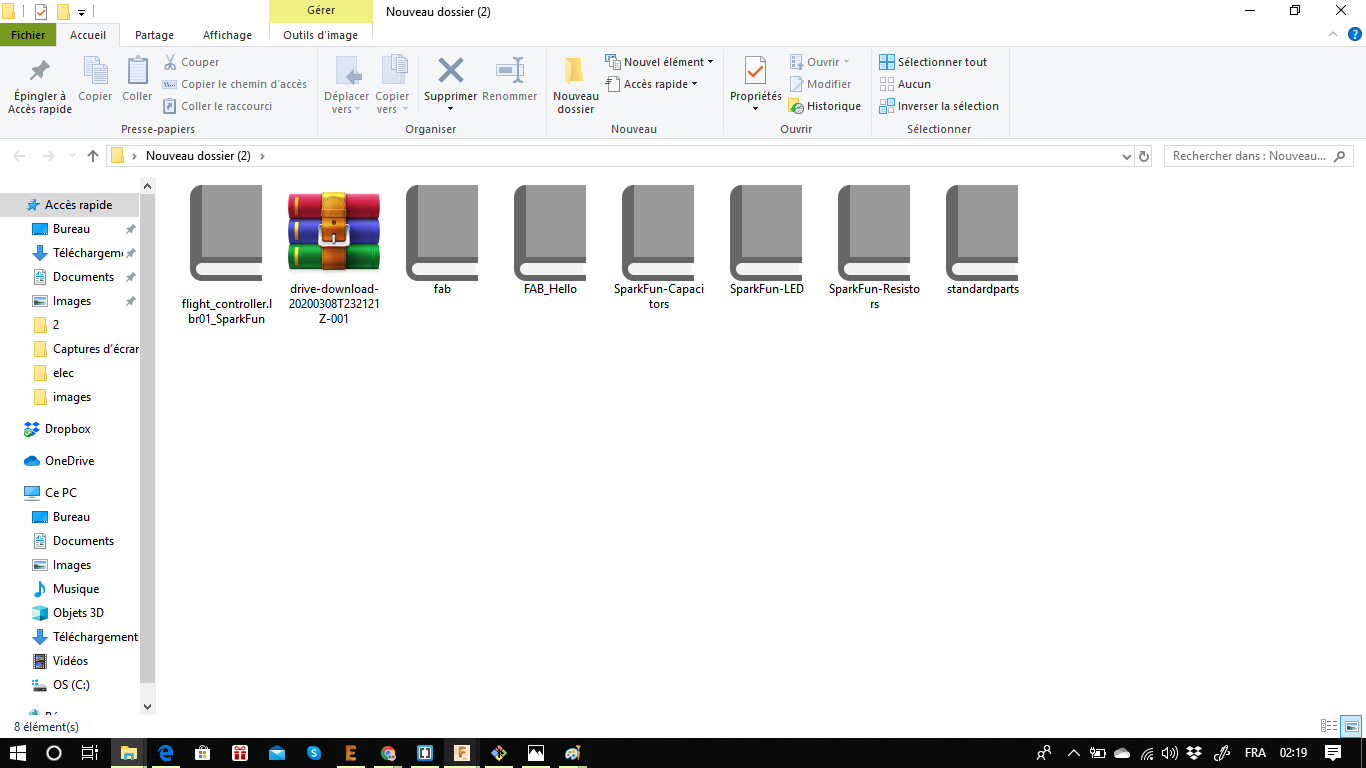
2- Then I extracted then I pasted the .lbr files in the library folder of Eagle.

3- I added the components for the schematic it’s pretty easy you just have to press library _ library manager_ in use .


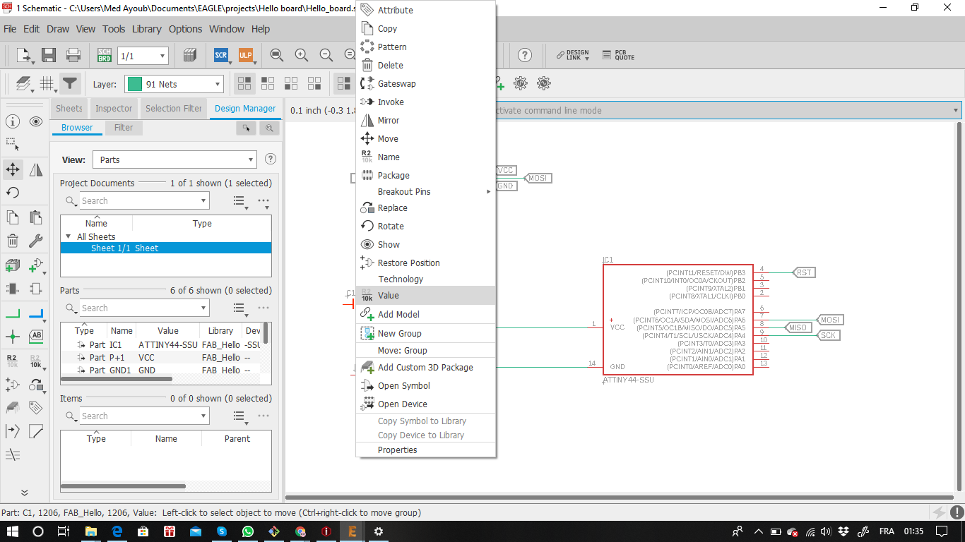


4- And this is the final result.

After the schematic completed i switched to design my board , to do that I pressed “BOARD” on the top of eagle menu as it shown below :

I got this where all the footprints were disordered, so I tried to arrange the components manually as it is shown below:


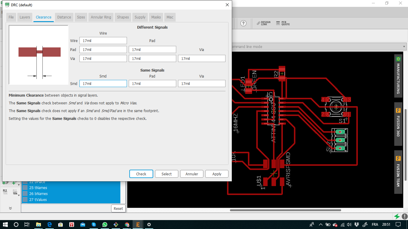
I choose 17mil clearance between objects in signal layers which was our instructor recommendation:
Hopefully, I found many useful tools that help me to check the errors in my design:


After I checked my design with our instructor, this was my final result:

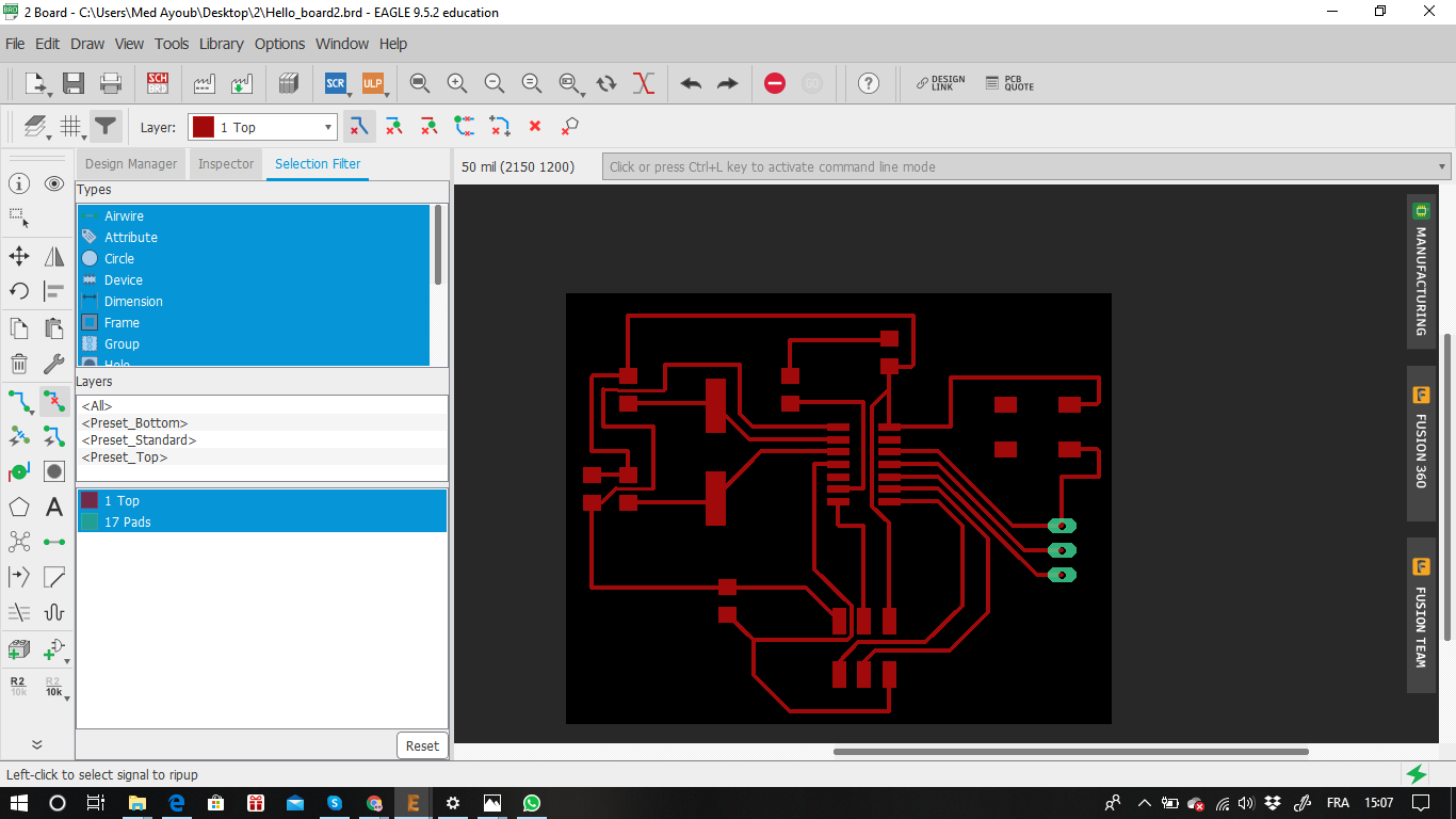
I hided all the layers exept (top , botom and pads) as it is shown below :

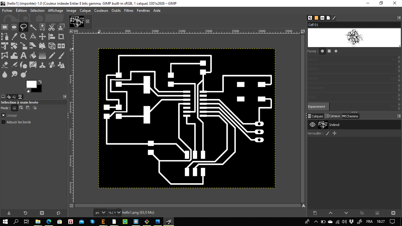
I exported my design as a png file, with those settings (monochrom and full)


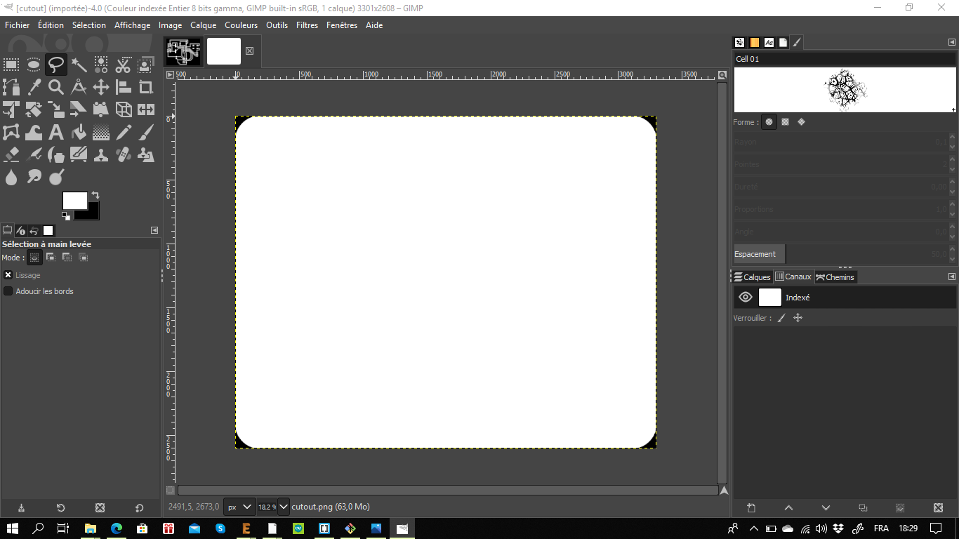
I imported the png image into GIMP software to design the cutout for my hello board:
Below are all my hello board files:
Hello board G-CODE generating, milling, soldring and programming.
A- G-CODE generating:
1- I uploaded my Traces PNG file to Fabmodules and I started to insert the settings and the parameters for the milling. Below are my steps which I followed :
a_ steps
-
Image(PNG) / TRACES (png)

- Outline format / G-Code

- Process / PCB TRACES(1/64)


2_ I Uploaded my hello board outline PNG file to fab modules after that I repeated thr same steps as for the traces before .But, the difference is that Iselected in the process window PCB outline as it shows below :


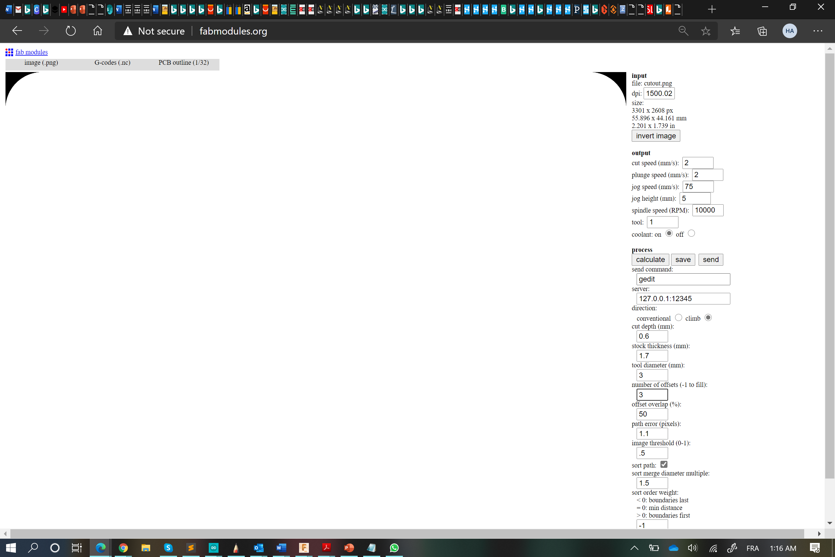
- Calculating G-Code for the hello board traces and the outline after that I saved the G-CODES ans I prepered to uploaded to the CNC software.


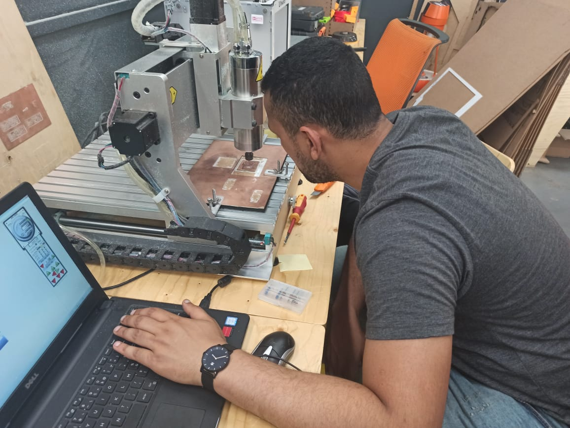
3- Milling:

4- Soldring:
-
To solder the hello board you need to prepare it’s components , soldring station , the multimeter to check the connection :
-
My hello board components:
-
AtTiny84 microcontroller
- 20 Mhz resonator
- Capacitors 1uF
- 2 resistors 10kohms
- 6 header Pins for programming(ISP)
- Red LED
- A 499 Resistor
- A push button


 This is the final result after I checked al it’s connection but as you can see I faced one prob with the push button while I was soldring it , so I picked up two jumper cables and conected both of them to their places.

Programming My hello Board:
- After finishing the soldring and wires connection check it’s time to programm Now ^^
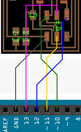
1- You need to connect your hello board to your arduino using the jumper cables as it shows below:


2- Open the arduino software there is some modifacations you need to do which are the following:
a- Go to file/Preferences/ Additionna Boards Manager URL’s and paste this link.


b- The link allows to find the hello board microcontroller so you can add the attiny 84 to your arduino software:
c- Now, go to sketch/ include Library / Manage libraries / attiny and instal the library
d- Go to tools / boards and select attiny microcontrolles / attiny 24/44/84 after that below select processor attiny84

e- Select Clock external 16 mhz which my cristal value , select the port in which your arduino is linked also as a programmer arduino as Isp

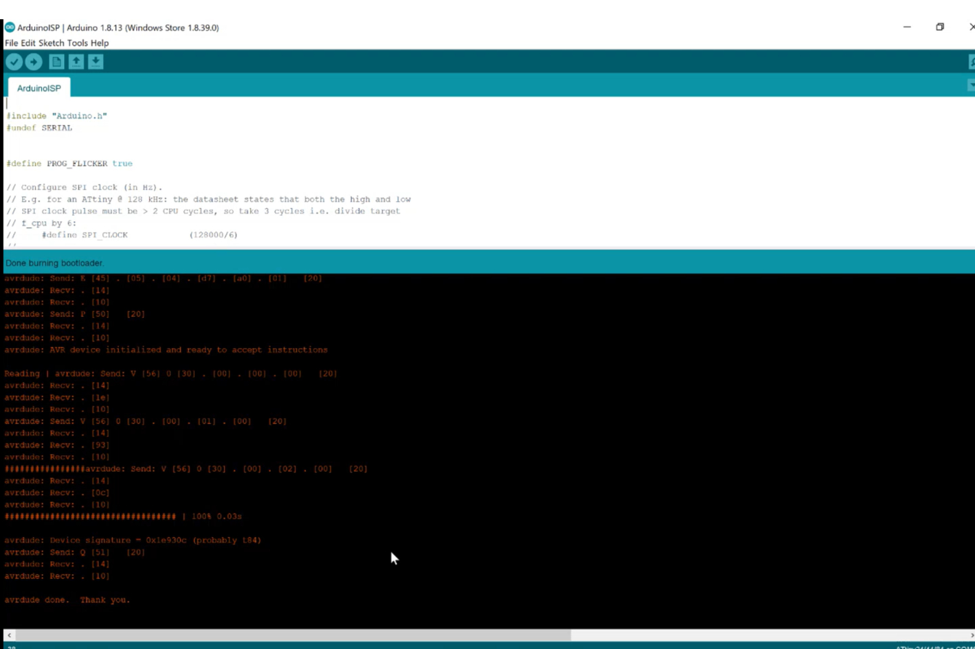
 f- Go to file/examples/arduino ISP after that there is a code will apear like it shows below:


g- Upload the code to your arduino to make it able to programme your hello board:

h- Now go tools : burn bootloader

i- you need to wait now and if the burn of the bootloader done succesffuly so every thing is fine ^^
This is it I burn the bootloader sucessfully
to check that every thing is fine I need to blink my hello board LED and it was good ÏT was blinking and below are the steps to do that :
1- Go to example / bacics/ blink and upload the code to your arduino , the is a bvery important point to highlight wich is you do not upload the code directly to your arduino but yopu need to upload it using a programmer because the hello board is not linked directly to your laptop but througt a programmer which is the arduio for that you need to go ; sketch / upload using a programmer

And the work is done ^^