4. Computer controlled cutting
This weeks Assignment: 
- Group assignment:
-Characterize your lasercutter,’s focus, power, speed, rate, kerf, and joint clearance.
- Individual assignment:
-Cut something on the vinylcutter.
-Design, lasercut, and document a parametric construction kit,accounting for the lasercutter kerf,
-which can be assembled in multiple ways,and for extra credit include elements that aren’t flat.
First part:(Group assignment): 
-
Laser cutter: Setup and Test:(Group assignment):
-
what is a laser cutter?
A laser cutter is a machine that uses a laser to cut and engrave material. Choose an image you would like to cut or engrave, optimise it for laser cutting, pick a material, and then press print on the laser cutter. This is a quick and easy way to replicate the same design on different materials, or create multiple copies of the same object.
-
How to use a laser cutter?
1-Decide what material you want to cut or engrave. Laser cutters can cut and engrave wood, plastic, cardboard, foam, fabric, and thin sheets of metal. Any material containing chlorine cannot be used due to the toxic fumes they produce. Avoid PVC, vinyl, and printed circuit boards.
_Glass can be engraved but cannot be cut.
_Thick metal cannot be cut.
2-Choose an image to cut or engrave onto your chosen material ( wood) .
3-Upload the image into RDWORKS V8 . Save the image file to your computer. Open the software and click “import” to upload the image to the programme.
4-Set the dimensions of your image to match the size of your material.
5-Optimize your image for laser cutting.
-
Adjusting the Machine
1-Place the material in the centre of the laser cutter.

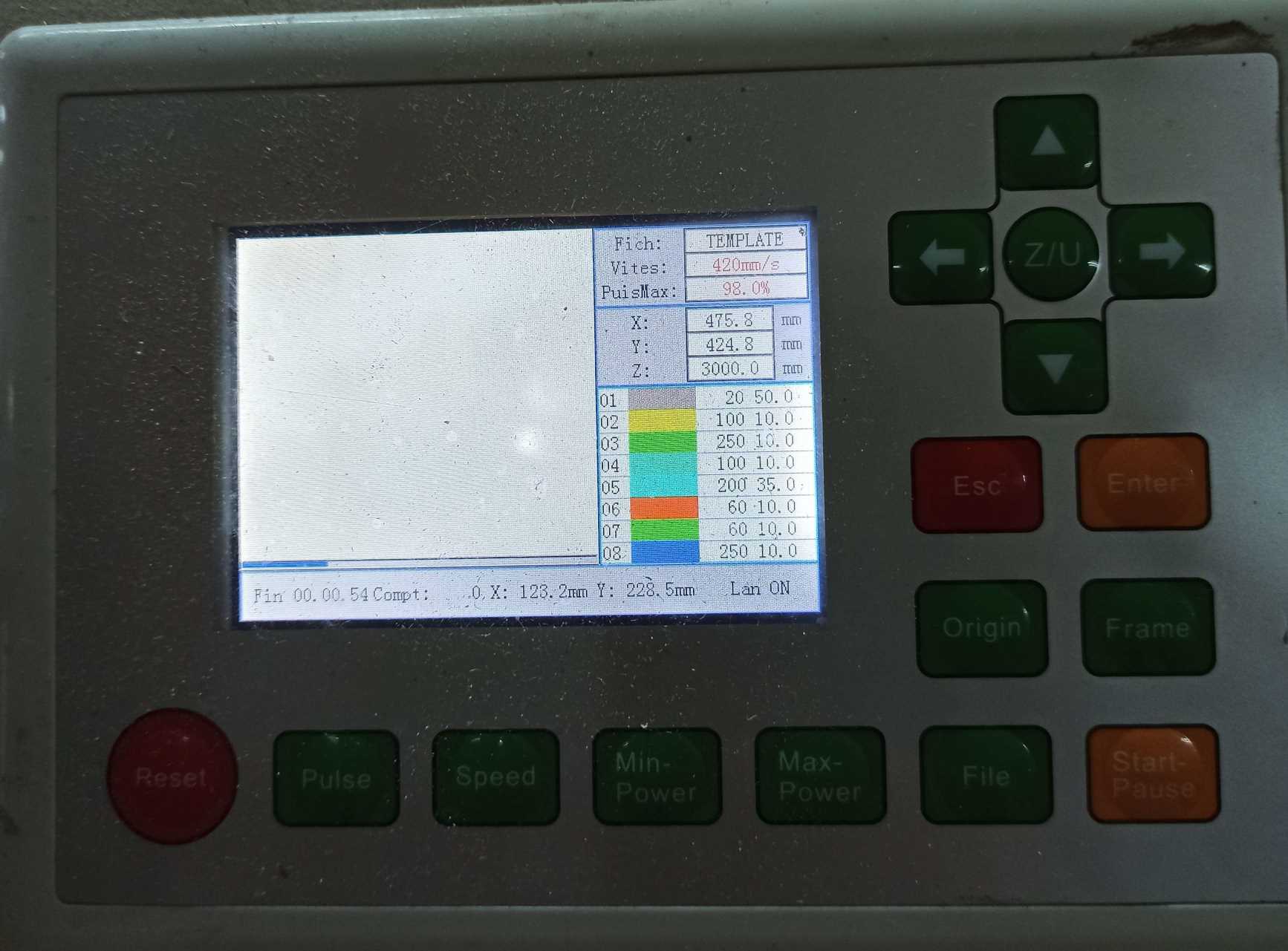
2-Clean the lens with rubbing alcohol.
3-Set the lens height ( see the image below).

4-Turn on the fume extractor.
5-Press start.

6- Switch ON the pointer
7- Unlock X/Y motor axes
Laser cutter characterizing: (Hardware)
-
Make test part(s) that vray cutting and dimensions, to characterize our laser cutter.
-
Tool : Laser cutter CO2.
-
Class: 3R (for this class, lasers are considered safe when handled carefully. There is only a small hazard potential for accidental exposure. For visible-light lasers, Class 3R lasers’ output power is between 1 and 4.99 milliwatts.
-
Laser Power : 100 watt.
-
Model: Golden Sign GS9070.
-
Materials: Plywood/Mdf 4mm; Cardboard 6mm; Plexigrass 5mm.
-

software:
- Before using the machine, We started designing our own Test Template using Fusion 360 in 2D sketching.

-In our team work we used (RDworks V8)[https://rdworks.software.informer.com/] as a software to manage and send the job to the laser cutter. so what is RDworks V8 ?
RDWorks is a powerful program that allows you to perform laser cutting engraving operations. The program has support for drawing points, lines (horizontal/vertical), polyline, ellipse/circle, rectangular/square, Bezier curve, text, and for CAD models such as DXF, AI and PLT
kerf test: 
-
what is kerf?*
-
Kerf is defined as the width of material that is removed by a cutting process. It was originally used to describe how much wood was removed by a saw, because the teeth on a saw are bent to the side, so that they remove more material than the width of the saw blade itself, preventing the blade from getting stuck in the wood.
Below is The final result of the group assignment.


We did also a Kerf test: Kerf is determined by material properties and thickness, the focal length of the lens and the gas used while cutting, I’ve designed a simple test in order to find a kerf. As in the previous picture we have drawn 9 rectangular pieces (10mm each) for 10 vertical cuts. This for make an average on the long distance.

- we have drawn 9 rectangular pieces (10mm each) for 10 vertical cuts. This for make an average on the long distance. determined by material properties and thickness, the focal length of the lens and the gas used while cutting,

- finally we’ve obtained a 0.3mm kerf for plywood with 3mm thickness.

For this weeks group assignment you can check our page by clicking here
Second part:(Individual assignment): 
- Individual assignment:
- cut something on the vinylcutter
- design, lasercut, and document a parametric construction kit,
- accounting for the lasercutter kerf,
- which can be assembled in multiple ways,and for extra credit include elements that aren’t flat.
-Design: 
I decided to creat a stand for my laptop using the parametric design .
1_Working on Fusion 360:

2_I added the parameters to facilitate my designing as it is shown below:


3_ I started to design the first leg of the laptop stand:


4_ I used the parametric setting to extrude the first leg
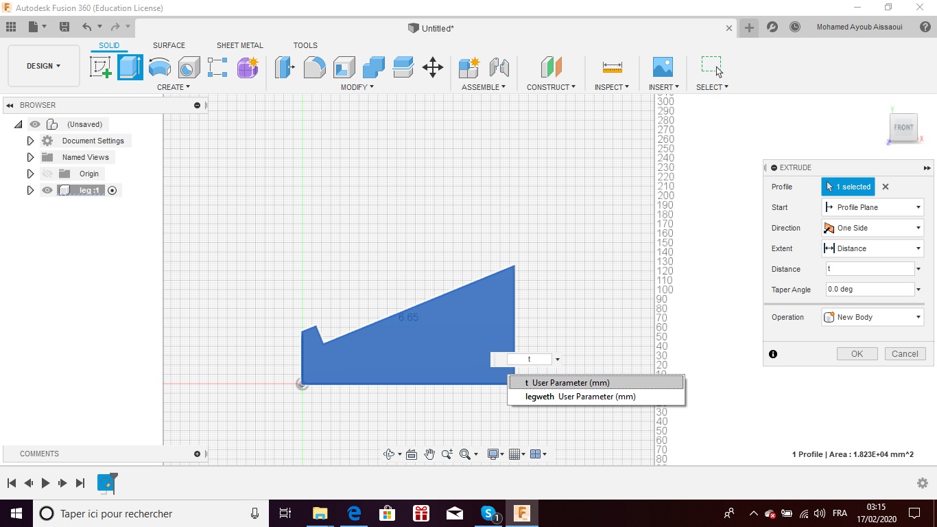
5_I used the extrude tool to add depth for the designed leg as it is shown below .


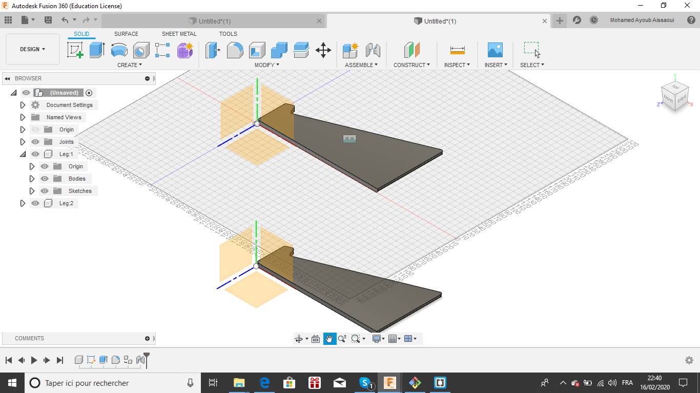
6_ I added fillet to the leg edges using the fillet tool.


7_To create the second leg, I used the clone tool (see the images below):


8_After I made the two legs, I started to design the top of the laptop stand. I made a 2 points rectangle.


9_ I designed two perpendicular sketch lines then I used the mirror tool to make 4 copies of the rectangle in the other sides


10_I extruded the top then I used the fillet tools for it as it shown below:


11_After the top was created ,I hided it and I started designing the two supports .

12_I selected_ new sketch_ on the (laptop stand) back as it is shown below


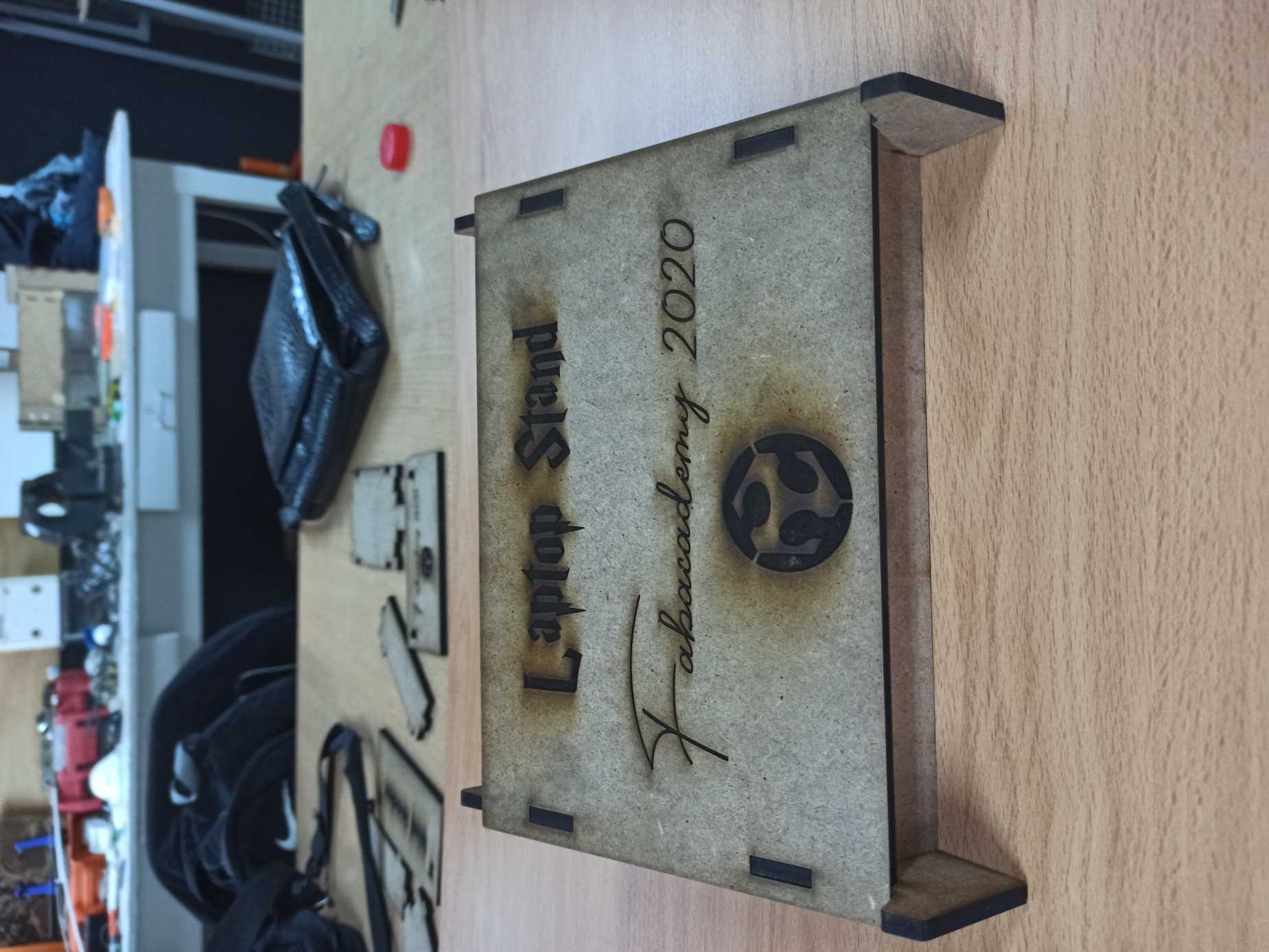
13_This is the final result .

You can find the link to the laptop stand file below:
_ Fusion 360 laptop stand file .
After that I exported each part of my design (The Top ,the two sides and the supports)as a DXF files to start cutting them by the laser cutter .

I imported the DXF files to THUNDER LASER program to start the cutting operation , knowing that I used the kerf test from our group assignment to have the right and the suitable cut.
- I choose these setting to cut my laptop stand with the laser cutter :
* Min Power(%)-1: 90

   * Max Power(%)-1: 90

      * speed(mm/s):30


I send the DXF files to the laser cutter .


-Finally, this is my laptop stand
You can find all the DXF files below:
Second Design:
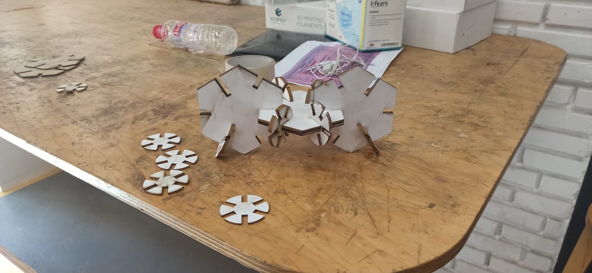
I designed two shapesa Hexagon and a small circle with a different size, that could after assemble it in a different ways and by next were the steps I used to do that:
1- Open fusion 360:
2 - Adjusting the design parameters
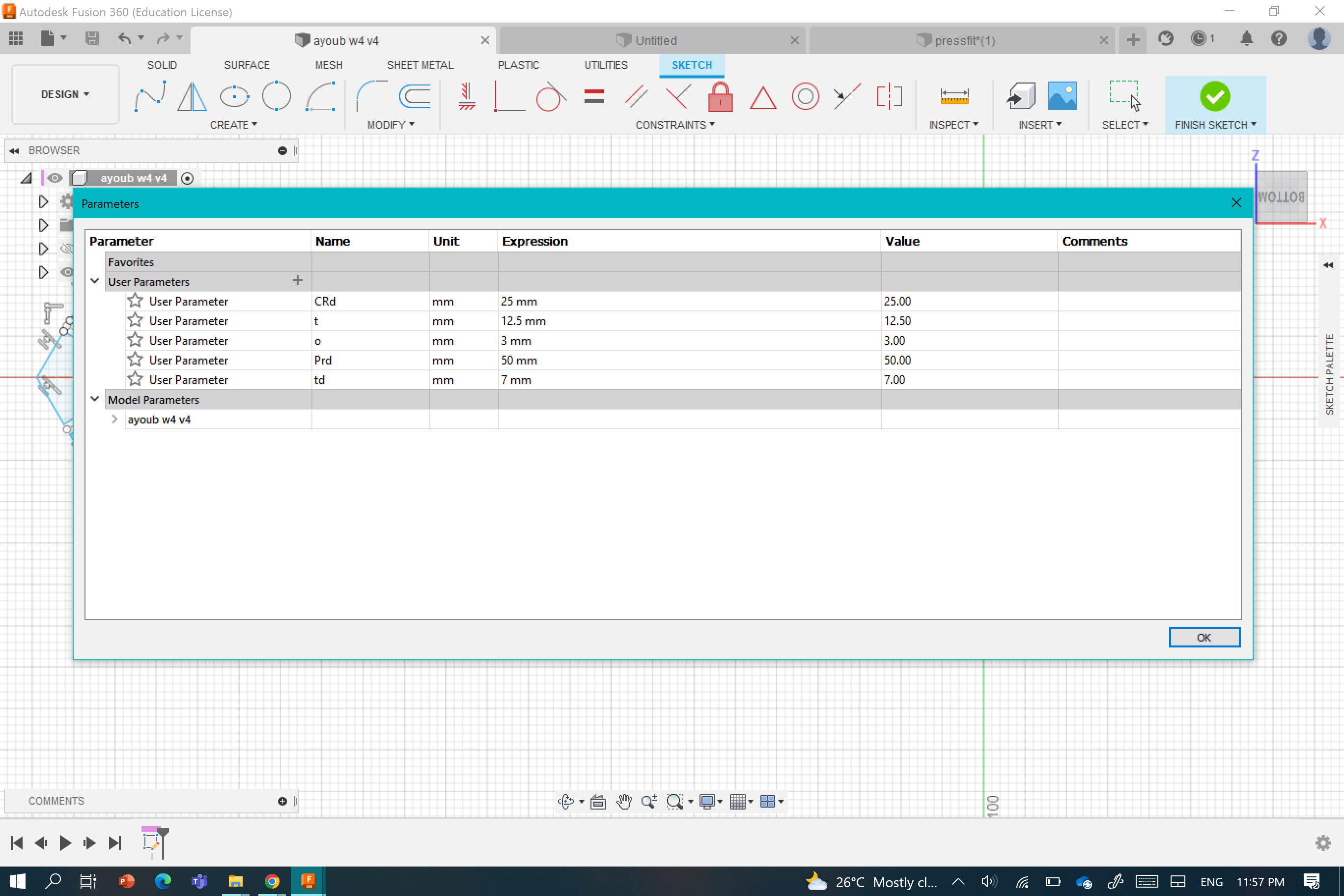
3 - These were the steps I used in my design
a - Design a Hexagon with the right parameters I metioned above, then in each corners,design a rectangle as it is shown below:


b- Redo the same with the second Small Circle:


4- Steps to cut:
a- Open laserCad software an d upload the DXF file of the design:

b- Uploading the file to the laser cutter:

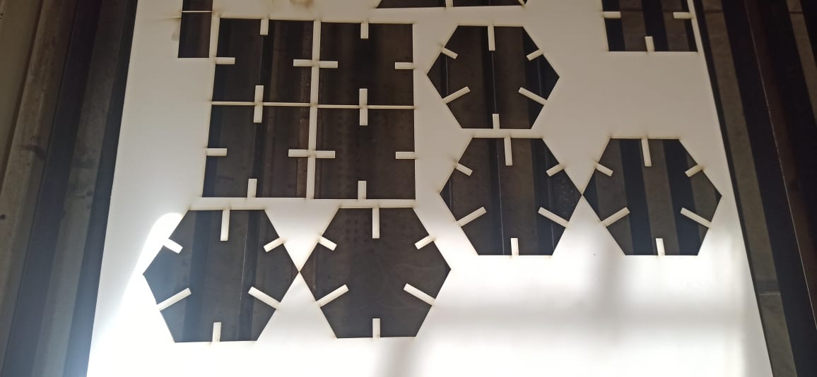
in this steps you can choose the suitable material you wanna cut it here is the result I optained:


Assumbling


Files
The vinylcutting:
So, what is vinylcutting ??
The vinyl cutter uses a small knife to precisely cut the outline of a picture into a sheet or piece of vinyl. The knife moves side to side and turns, while the vinyl is moved beneath the knife. What results from the cut process is an image cut into the material.

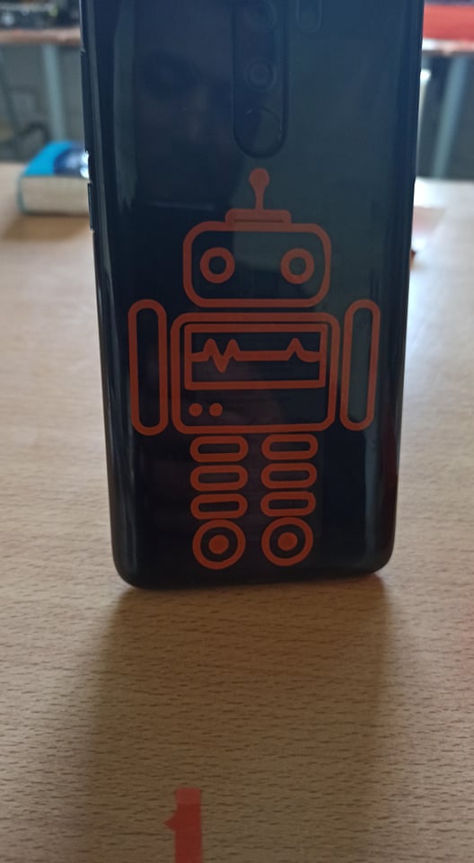
For the vinyl cutter task I sought for a logo that could be suitable for my final project, so I choose this one as it is shown below:

In our fablab we use Roland Camm1 GS-24and CutStudio as software to controle the machine .


Steps to cut:
1- I imported the logo in the cutstudio software ,I fixed the cut parameters. After the software automatically converted the logo to a vector-based image for smooth cutting :
 .
.
2- I sent the logo to the vinylcutter :


3- I cut the logo using the scissors:

4- I used the painters tape to move the logo from the vinyl material to the new surface (my Phone).

5- finally, I got this :
You can download the logo file from Here.