Group Assignment: Electronics_Production
characterize the design rules for your PCB production process
Fab Lab Kamp-Lintfort
The objective of our group project for this week was to characterise the PCB-making mills we had at our disposition. In the FabLab, we have a Roland MDX-40A machine, while in my little satellite lab, I have a Sainsmart Genmitsu 3018 Pro. Both machines needed characterising.
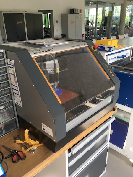
Roland MDX-40A
The FabLab workhorse is a reliable beast. Looks good too!
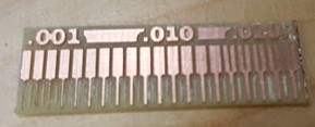
The team that did the work in the FabLab produced a lovely example of a test strip using the settings on the Roland mill.
They’ll describe in their own words the magic they used to achieve that result.
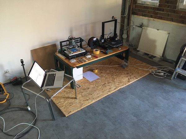
Sainsmart Genmitsu 3018 Pro
In our satellite workshop in Qualburg, we have a little no-frills mill, which also doubles as a very dangerous lasercutter.
Characterize the design rules for your PCB production process: document feeds, speeds, plunge rate, depth of cut (traces and outline) and tooling.
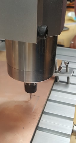
The Genmitsu mill is a sturdy little beast, but it has no safety switches anywhere, so it has to be operated with care. The worry isn’t so much the operator as the steppers and, as we’ve discovered a few times now, the milling tools.
To characterise the mill, we used the linetest.png example file from Neil’s lecture, shown below.

We used FabModules to generate the g-code for the job, with a cut speed of 4mm/s and tool diameter of 0.4mm. For the rest of the parameters we just accepted the defaults. When we ran the cut in air, with no tool, it was clear that the machining speed had to be cut back, as recent experience had taught us that none of the tools in the FabLabchen can handle that kind of force. That led us into the g-code. (We could just have gone back to FabModules and changed the speed, but we were curious to see how the code was laid out.)
To understand the g-code, we referred to the following document, from machmotion.com. Using the guide, we annotated the header of the FabModules g-code as follows (FabModules is not verbose - the comments after the semicolons are ours).
%
G17 ; xy-plane
G20 ; set units to inches
G40 ; compensation off
G49 ; cancel current tool offset, z axis
G54 ; work coordinate system X0 Y0 Z0
G80 ; cancel canned cycle
G90 ; absolute distance mode
G94 ; feed rate units per minute (sets units for F words)
T1M06   ; T1 picks tool #1, M06 executes the tool change
F4.7244 ; feedrate in inches per minute (set by G94)
S1000   ; set the spindle speed
G00Z0.1969  ; G00 - fast move to Z-coordinate
M03     ; start spindle clockwise
G04 P1      ; hold still for a unit of time
Z0.1969     ; move to the Z-coordinate
G00X0.0514Y0.4252Z0.1969    ; move quickly to the starting point
G01Z-0.0040 F4.7244     ; plunge to the cutting depth
F4.7244             ; pick up the speed
G01X0.0584Y0.4262Z-0.0040   ; start cutting
The exploration of the code explained a few of the problems we’d been facing with the Genmitsu. The first was the switch to inches as units. We’d noticed that the machine controller sends the motors off into orbit after the job: instead of jogging by 10mm, it was jogging by 10in. We couldn’t figure it out until we saw the G20 line in the g-code. The other thing we noticed was that the job would simply finish at the last point of cutting, which made it difficult to then position the milling head for the outline cut. So we added two lines to the end of the g-code, between the M05 stop spindle and M30 program stop lines:
G00X0Y0Z0.1969          ; go back to zero position
G21             ; return units to millimetres
The first of those lines zeros the cutter back to the home position, but still positioned safely above the board. The second we’ve just added, and are hoping will reset the machine controls so that it doesn’t have to be hard reset after every job.
Finally we discovered that the Genmitsu requires the DOS CR/LF text format, so we had to translate the code from the Unix/Mac format provided by FabModules. This we did with the following command in Terminal:
perl -pe 's/\r\n|\n|\r/\r\n/g' linehalf.nc > linehalf-rn.nc
cp linehalf-rn.nc /volumes/Genmitsu
The first line converts the newline characters into CR/LF pairs. The second copies the new file to the SD card for the mill.
The complete g-code file is available here
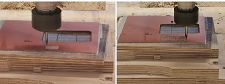
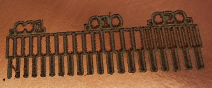
The results of our tests are shown in the picture below:
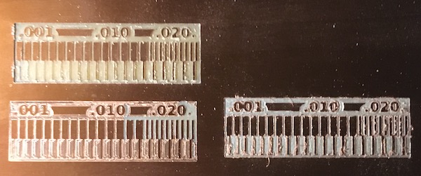
We tried three different setups, shown in the left hand picture. The bottom left panel shows the results of an engraver tool with its z-axis calibrated at the bottom left corner by descending until a piece of writing paper was just snagged by the tip of the tool against the PCB stock. The result is that the tool doesn’t cut deep enough to clear away the copper, except in the top right corner, where the top of the PCB is warped up towards the cutter. The cuts are clean, but not deep enough.
The bottom right panel shows the results of using the same cutter, calibrated in the bottom left corner with the same piece of paper but this time, after the paper was removed, the spindle was started and the engraving tool driven down 0.200mm (0.1mm for the paper, and another 0.1mm into the copper). The result is a bit more jagged, but the traces are mostly clear.
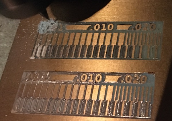
The top left panel shows the results produced using a 1/64in two-fluted square sided milling bit. The results shown are the second pass, created in the same way as described above for the bottom right panel. The second picture above shows the results of the first pass - to the left of the test fingers, the failure to remove the copper on the first pass.
Lessons learned
- Run the machine at max 2mm/s with the small bits
- Calibrate by catching the paper and going down one more 0.1mm step (with spindle on)
- Add the two lines to the end of the g-code to reset the machine after the job
- Convert the FabModules file to DOS format if the machining is to be done from the SD Card (with Candle running on a computer via USB, the conversion is not necessary.)
- The plunge rate could be faster, and the clearance could be smaller, but both can be lived with.
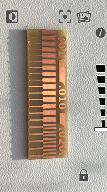
Characterize the design rules for your PCB production process: document feeds, speeds, plunge rate, depth of cut (traces and outline) and tooling.
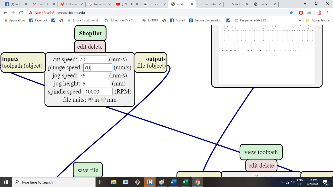
what is the smallest trace I can mill make a copy of the digikey electronics ruler how fast to run the machine () 5mm/sec is usual plunge rate (default FabModules) depth of cut is 0.1mm tooling from fab inventory
Characterize the design rules for your PCB production process
To do the group assignment, I milled this line test file. The tool I used to mill this is the carving V-bit end mill that came with the Snapmaker machine. Its properties are: Solid Carbide, Single Flute, 30 Degree, 1/8'' Shank.
The first thing I did was to convert the png file to DXF, then insert this into Fusion. After this I then extruded the traces, followed by the outline.
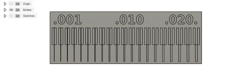
Then I prepared it for milling by setting it up as '2D Contour'
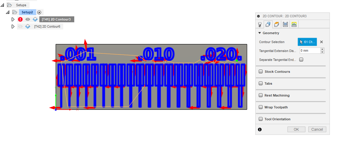
Then I milled it.
Below is the picture of the finished product.
It is worth noting that this could have been done properly had it been we had 0.2 - 0.4 end mills. However, I had to use what I have to solve the problem at hand.
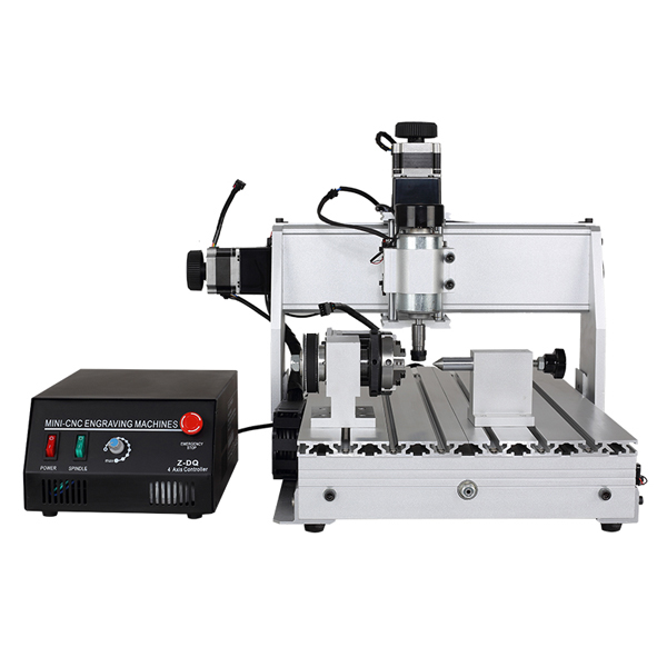
Fab Lab ENIT
For this week’s group assignment we had to characterize the specifications of our PCB production process on our CNC 3040. The software that we used for milling was Mods, online at Mods and send nc files trough Mach3 software sender.

We did a linetest using these two files:
-
linetest.png to milling the traces with 1/64 (0.4mm)bit;
-
linetest.interior.png to cut the outline with 1.4mm bit.
we had to characterize the specifications of our PCB production process on our CNC 3040.
Before attempting to mill we had set the machine as follows:
-
prepare a sacrificial plane;
-
using the double-sided adhesive tape, attach the 20mm MDF plane to the table; then attack the FR1 base on the sacrificial plane;
-
attach the milling bit in the collet and make sure it is 2 or 3 mm from the surface of the FR1;
-
zeroing the Z height, dropping the tip on the plane, making sure that the Z can theoretically get off at least the right amount to be able to mill.
-
zeroing the X and Y axes starting from the left-bottom side of the FR1 board.
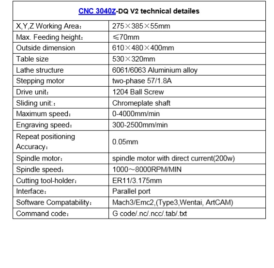
data sheet for machine
After using the machine we start to read her data sheet
software
The software that we used for milling was Fab Modules, online at FabModulesormods and send nc files trough Mach3 software sender.
Fab Modules is a browser-based CAM system, which allows to generate toolpaths for and control lasercutters, CNC-mills and waterjets commonly found in fablabs. we test the machine
 )
)

First we generate the gcode
what is a g code ?
G-code is a language in which people tell computerized machine tools how to make something.
how to generate a g code?
To generate ower g code we use a software whitch is mods
- open the software click on the mouse’s right button.choose programes , click to open an server programe and choose shobot mill 2D png
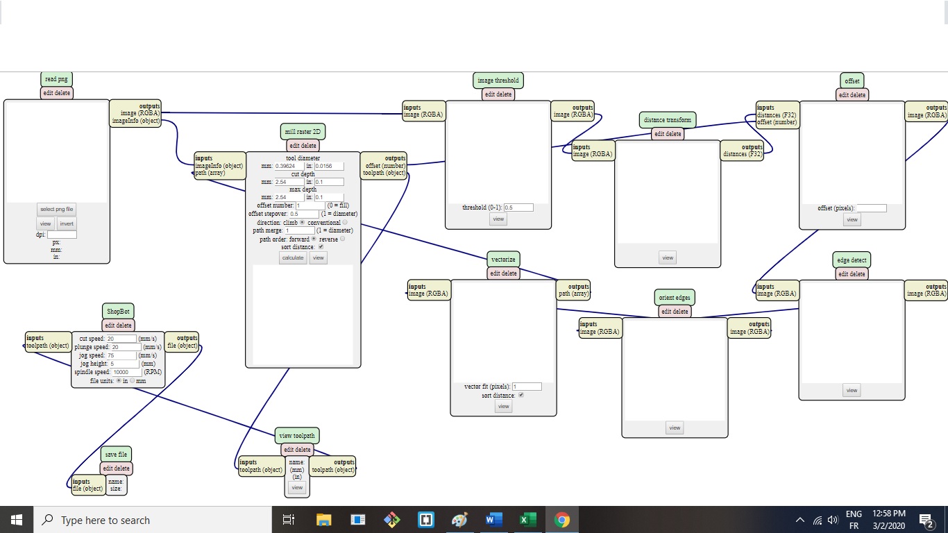
- we import ouwrs files png for test click to select file
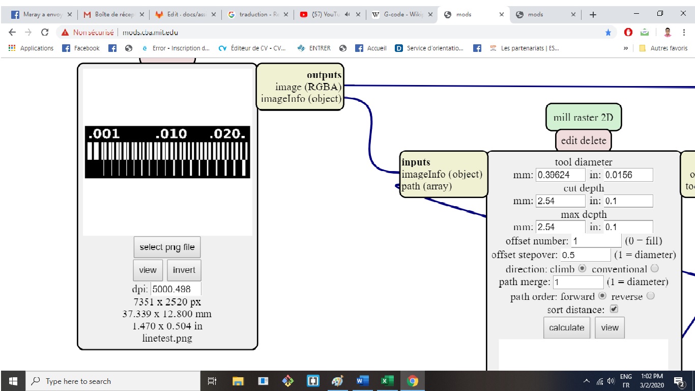
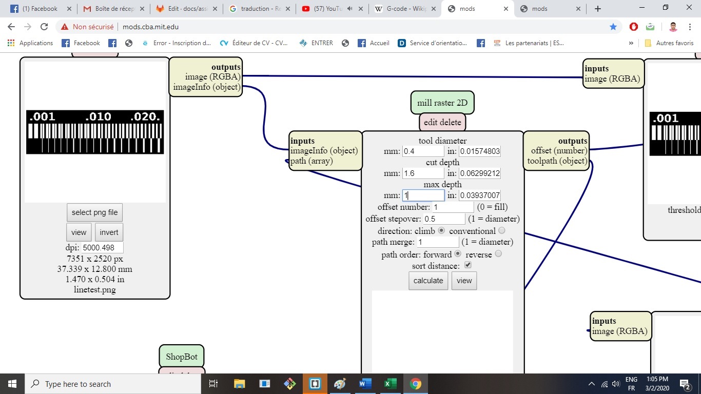
- we configurate the setting of cut we choose tool diameter ,cut depth and offset number
-
click to calculate
-
we save the fils of ower g code
how to mill the pcb ?
we exporte the gcode to the machine controller .we calibirate the Z we fixe the plate and we choose ower origin and click start
Below the result: