Applications and implications
Have you answered these questions?
What will it do?
The project's purpose is to provide persons who have lost their hands a second opportunity by designing a prosthetic hand that fits and meets their daily needs. Using digital fabrication methods to implementing solutions for each individual case , including 3D scanning, electronics, and other 3D printing techniques to create a suitable solution.
By combining parametric CAD file dimensions with parameters that may be easily established according to the desired size, the model is adjustable in size. Especially since the hand can be scanned and the 3D Scan in the 360 Fusion can be simply modified. The model is designed in a parametric manner to fit each finger and, in the future, to fit different patients.
This project will enable anyone to take a design, scale it to the needed size, and print it to create the main part without having to assemble 50-200 small parts. Because the main part was printed in a single stage and the same components can be used in similar designs with different sizes, the final stage of the project will be to easily add electronic components to it.
Who has done what beforehand?
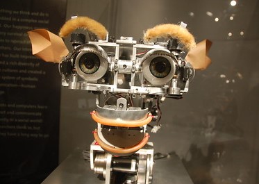
Inmoov
Brunel Hand
Hackberry
FABLE
TINA
Ketlli Tozaj Final Project
In many ways, my Project is unique:
-The main body will be printed in place, which means that all the main body parts can be fabricated in one step using a 3D printer, this will reducing time, effort and cost.
- Scalable by connecting the dimensions of the parametric CAD file to parameters that can be easily changed based on the desired size
- Each joint of the hand can be controlled separately, which brings the hand closer to the real hand and makes daily work easier for users.
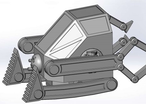
What will you design?
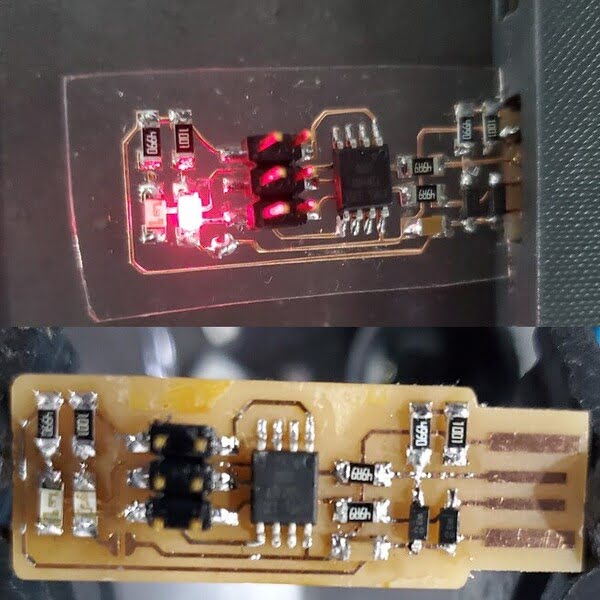
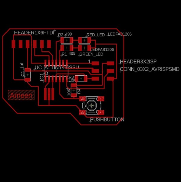
-PCB with atmega328p microcontroller and Similar to Arduino in dimension and arrangement of pins to match the shield.
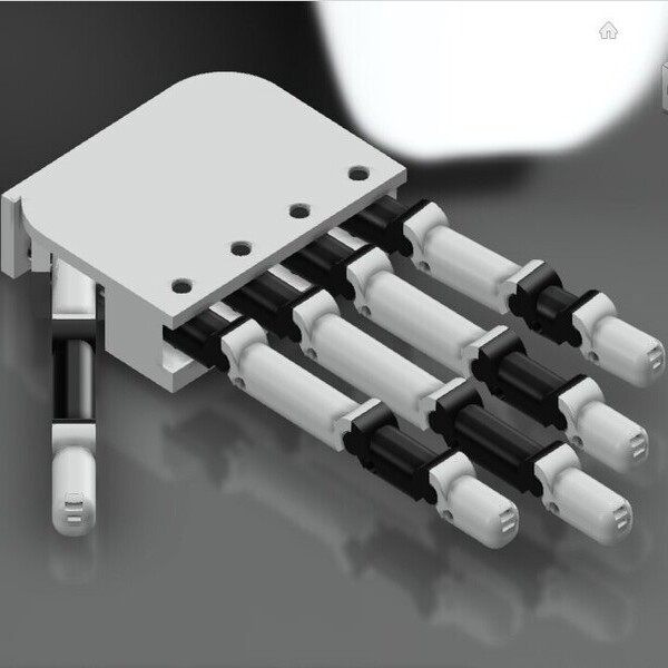
-Full hand design and part of the arm with full details such as the places of the motor and strings ...
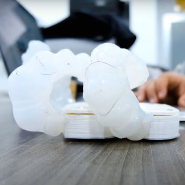
-A piece of connection between the prosthetic hand and the end of the natural limb.
What materials and components will be used? & Where will they come from?
Input and Output component
Componant Name
Quantity
Cost (JD)
Supplier
MYOWARE MUSCLE SENSOR
3
55*3=165
MYOWARE
DISPOSABLE SURFACE EMG/ECG/EKG
ELECTRODE - 24MM (10 PACK)1
10
ELECTRODE
MG996R METAL GEAR SERVO 180 DEGREE
7
7*12=84
SERVO
MG90S METAL GEAR MINI
SERVO MOTOR 180 DEGREE9
9*7=63
MINI SERVO
Electronics Part
Componant Name
Quantity
Cost(JD)
Supplier
ADAFRUIT 16-CHANNEL 12-BIT PWM/
SERVO SHIELD FOR ARDUINO1
25
SERVO SHIELD
WIRE JUMPER
-
5
FEMALE/MALE
FEMALE/FEMALE
MALE/MALE
Board part
Componant Name
Quantity
FR4 board
1
Atmega 328p
1
Crystal 20MHz
1
Push bottom
1
Power Jack
1
Voltage regulator 5V 1A
1
Voltage regulator 3.3V 1A
1
cap 1M
2
cap .1M
1
Red Led
2
Green Led
1
yellow Led
1
Resister 499
4
Resister 0
7
ISP 2*3 headers
1
FTDI 1*6 headers
1
1*10 female headers
1
1*8 female headers
2
1*6 female headers
1
3D Printer Material
| Componant Name | Quantity | Datasheets |
| Ultimaker Nylon Filament | 1 | Datasheets |
| Ultimaker PLA Filament | 1 | Datasheets |
Other Part
| Componant Name | Quantity | Datasheets |
| ECO flex 30max | 1 | Datasheets |
| M3 screw and nut | 40 | |
| M5 screw and nut | 40 |
What parts and systems will be made?
-PCB with atmega328p microcontroller and Similar to Arduino in dimension and arrangement of pins to match the shield.(Milling)
-Full hand design and part of the arm with full details such as the places of the motor and strings ...(3D printed)
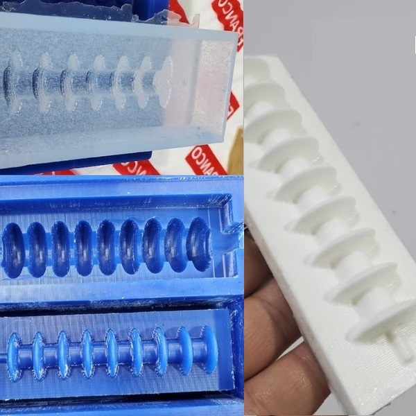
-A piece of connection between the prosthetic hand and the end of the natural limb.(3D printed & molding and Casting)
What processes will be used?
CAD (2D and 3D design)
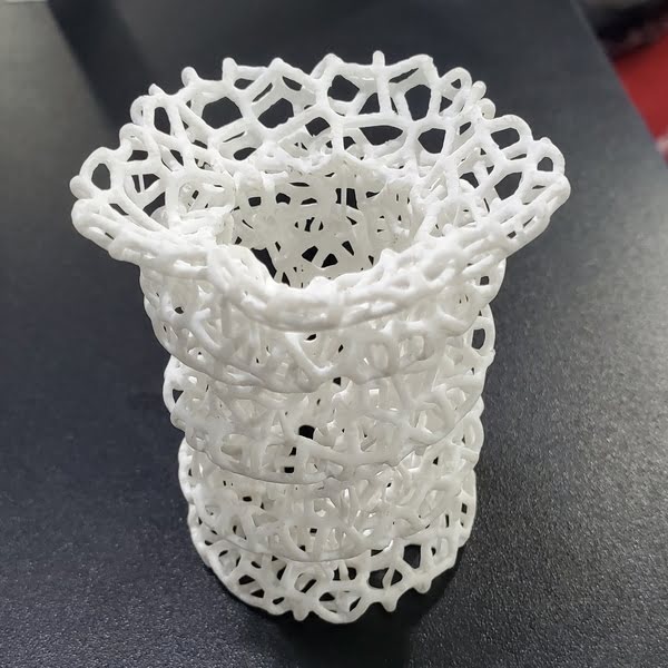
3D printing
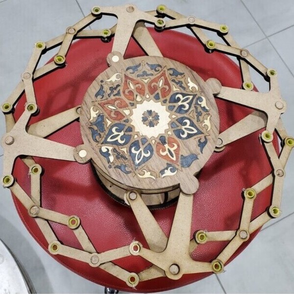
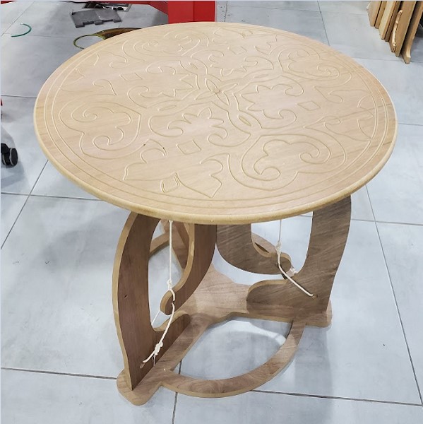
Laser cutter
Electronics Design
Electronics production
Input and Output Device
Molding and casting
Embedded Programming
What questions need to be answered?
I need to figure out how to connect the input and output in the coming weeks so I can get as many moves as possible.
How will it be evaluated?
The goals:
Ease to fabricate
Easy to use
Low-Cost
Work effectively
Note: that the control system still requires a lot of development, and the emphasis will be on design.
Project plan
02-Feb Modeling the Conceptual Design.
23-Fab Test finger joint(by 3D printer).
16-Mar To produce finger , experiment with different materials and printers.
23-Mar To see if a thin coating of silicon can be fabricated to cover the hand, try it out.
30-Mar Actuators, Servo motors, Pneumatic motors, and Stepper motors are all being tested.
10-Apr Design Amino PCB to fit with servo shield.
20-Abr The functionalities of myoware and libraries Using a simple Arduino script, I was able to read signal from Myoware using the Arduino IDE.
27-Apr Try to control servo motor with Amino board and servo shield.
11-May Finalize the design.
25-May Start printing the parts.
28-May Start assembling the parts.
01-Jun Start programming.
03-Jun Troubleshooting.
08-Jun Create the slide and video
13-Jun Presenting