Computer-aided design
2D Design
File to Download
2D Deign
Inkscape is a Free and open source vector graphics editor for GNU/Linux, Windows and MacOS X. It offers a rich set
of features and is widely used for both artistic and technical illustrations such as cartoons, clip art, logos, typography,
diagramming and flowcharting. It uses vector graphics to allow for sharp printouts and renderings at unlimited resolution and
is not bound to a fixed number of pixels like raster graphics. Inkscape uses the standardized SVG file format as its main
format, which is supported by many other applications including web browsers.
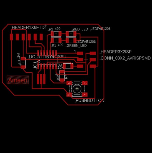
I decided to use it to make a logo so I looked for a picture with my name in an old font.
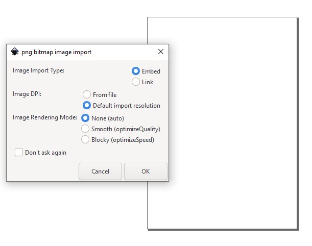
Open it with Inkscape
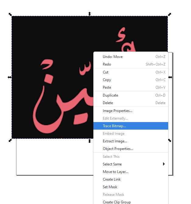
Click right on picture and select trac bitmap.
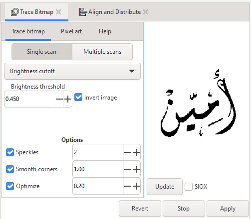
Put check in invert image and press apply.
Delete old photo.

Draw circle with red stroke and empty fill around the name

3D Design
File to Download
Fusion 360 file for the hand
Our assignment in this week was to model something related to our final project. I have good knowledge of CAD software; I have three years of experience with Creo and SolidWorks. A few months ago, I started dealing with the Fusion 360, which is available in the Lab. So, I decided to use Fusion 360 to design the mod for the final project.
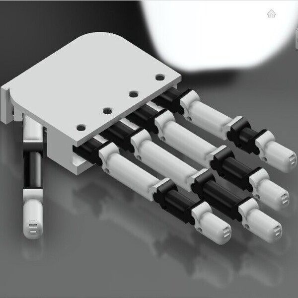
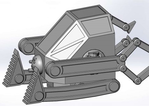
My final project is to create a prosthetic hand. So, in this week, I'm going to try to make a model for the hand, The finger mainly consists of fifteen phalanges" finger bone ". These bones are very similar to each other, the mainly different is length in one hand and the diameter from hand to hand.
As a result, I will design two bones, connect the design with a parameter, and produce the rest of the bones by making some changes.
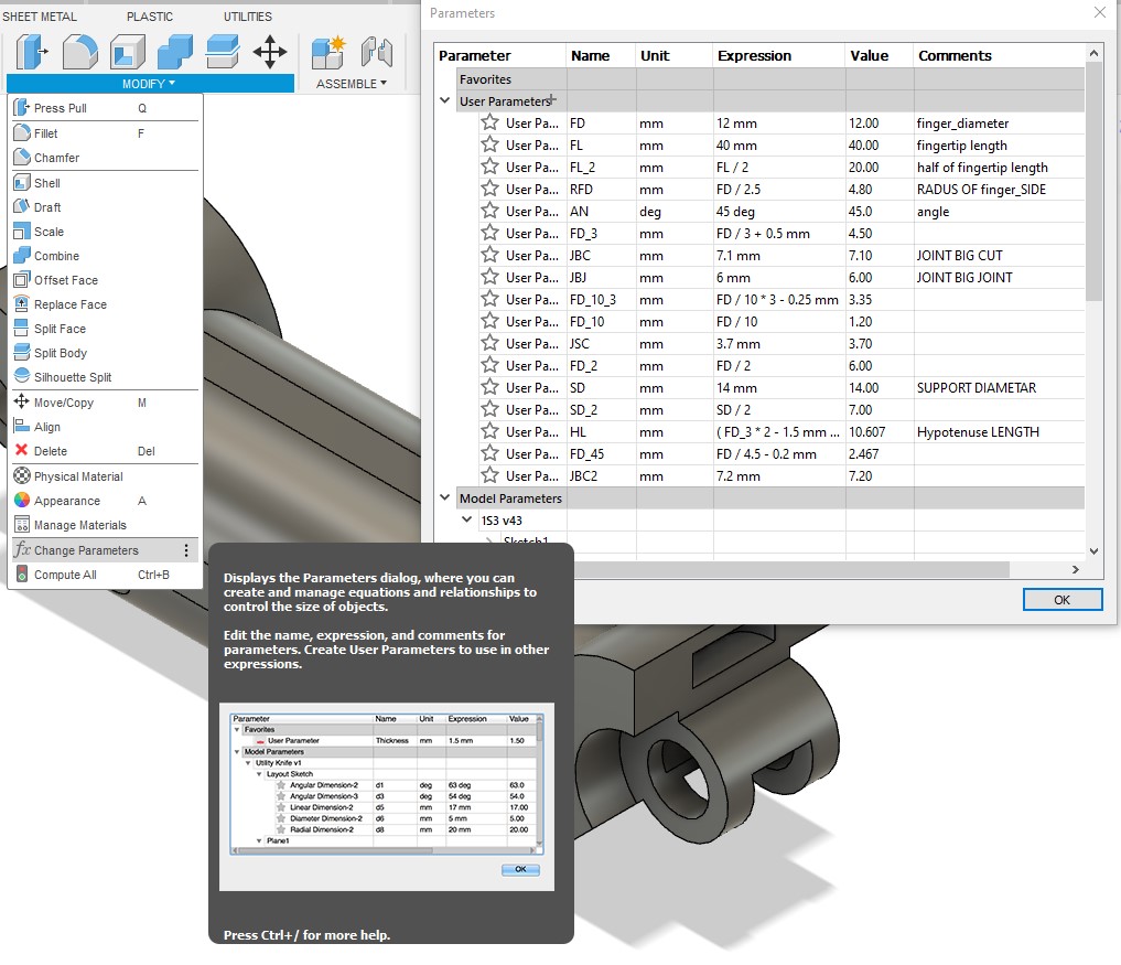
Adding the parameter
Choose the option change parameter from modify list then add the parameter in the pic.
Note: joint dimension is constant to keep the finger strong and the clearance for 3d printed.
Sketches & Features
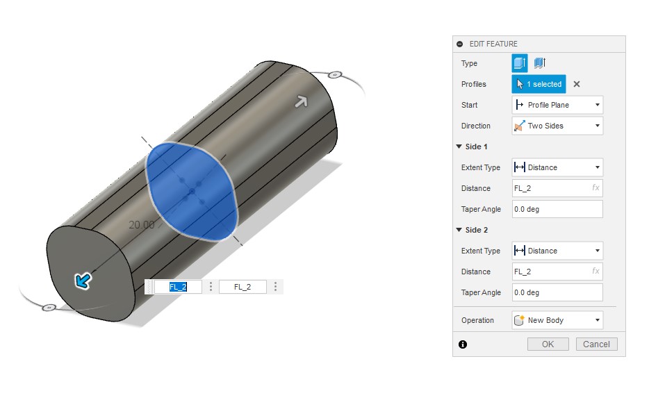
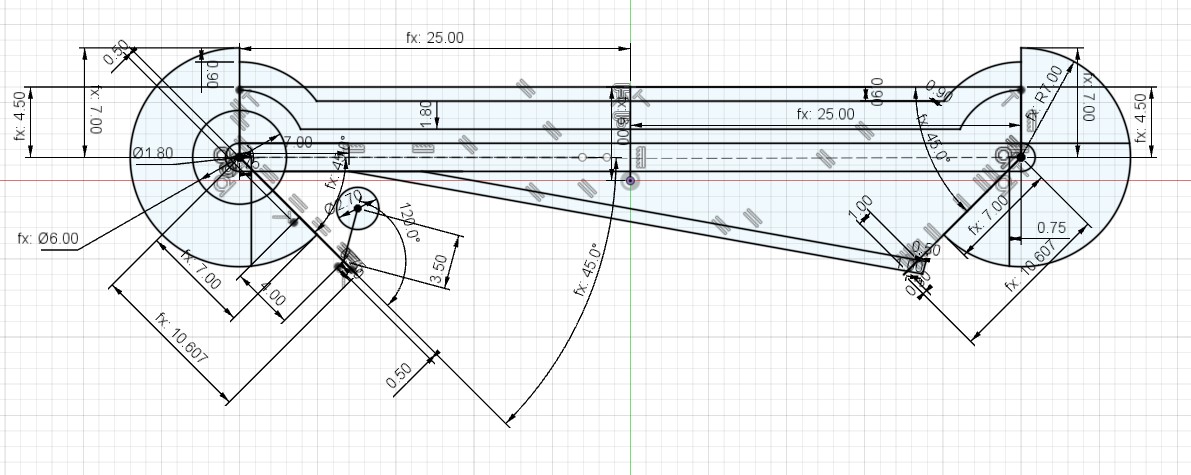
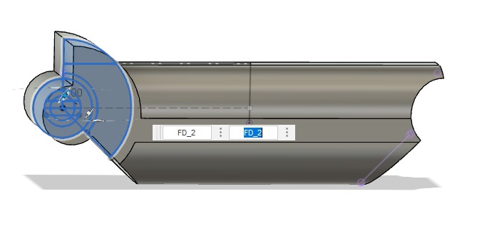
Draw a square with side length L and make filet 4mm at corner then extruded it from both side FL_2
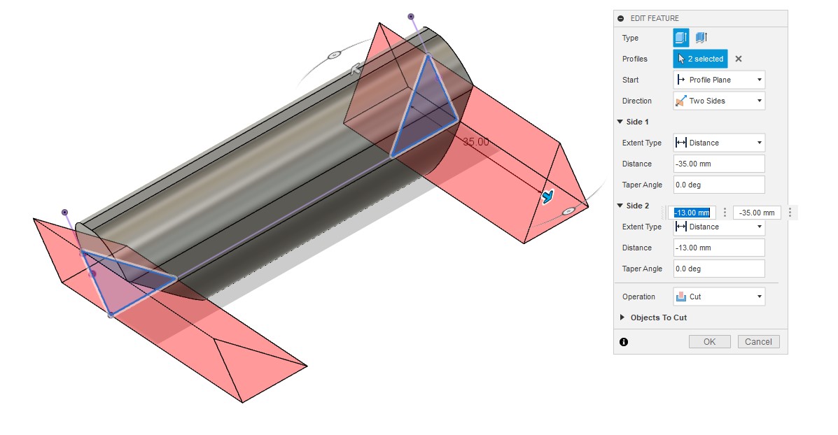
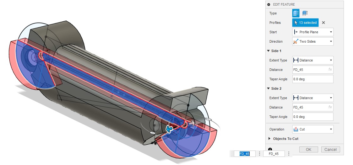
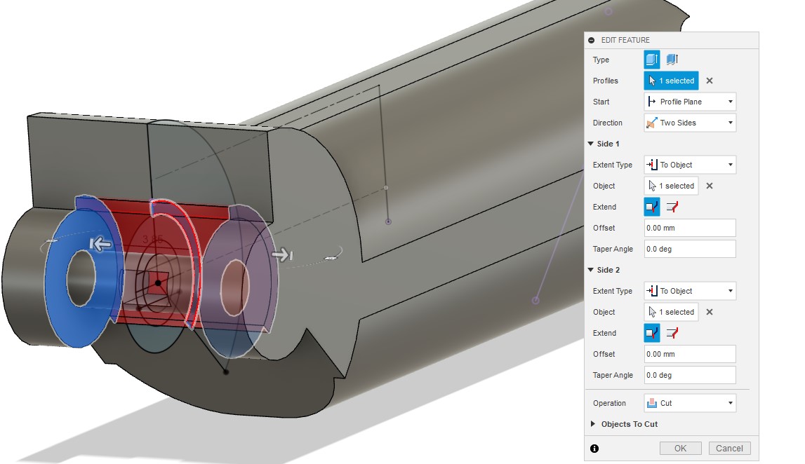
Draw a triangles with 45-45-90 angle and make top corner at a distance of two thirds from bottom then extruded it from both side and cut it
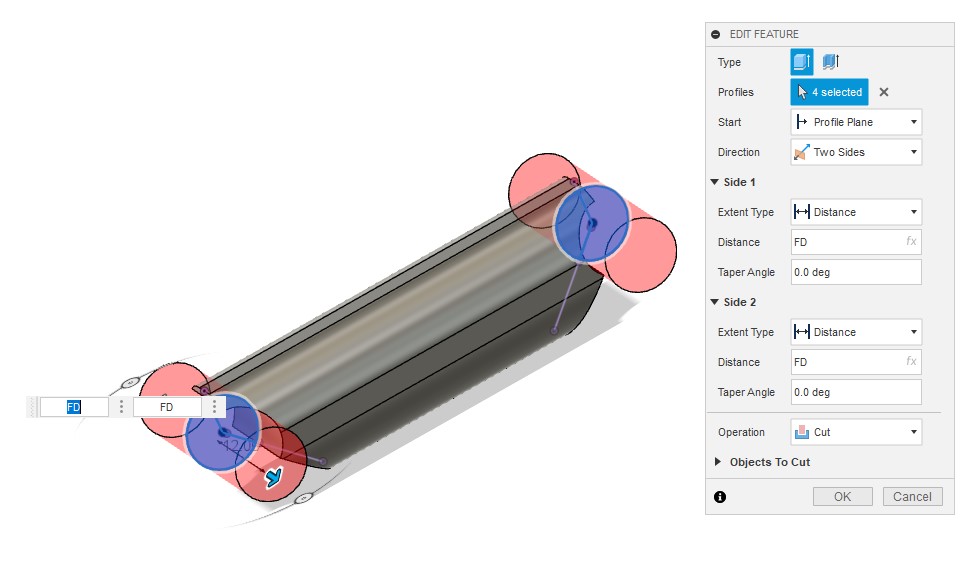
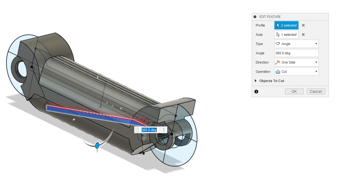
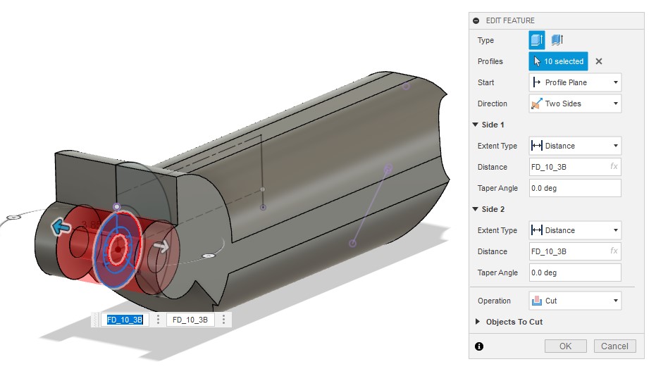
At the top corner of the triangle draw circle with 7.5 mm diametar then extruded it from both side and cut it
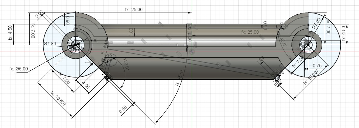
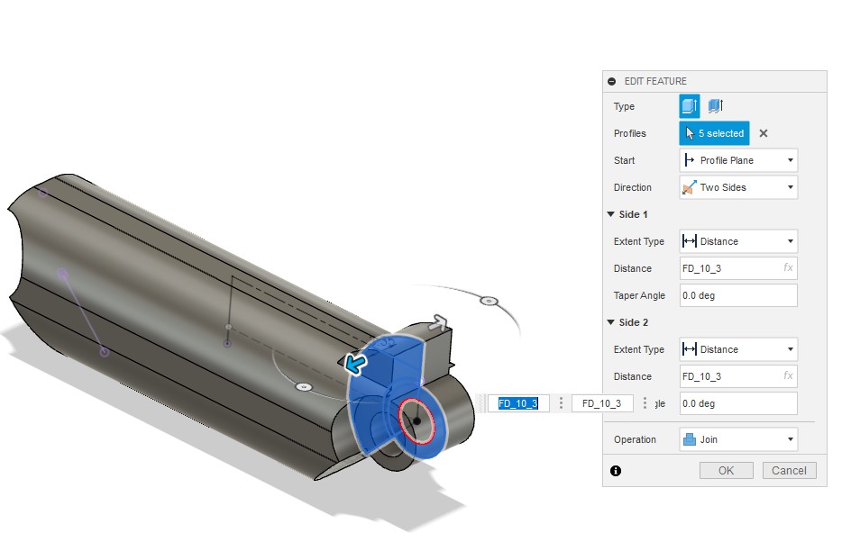
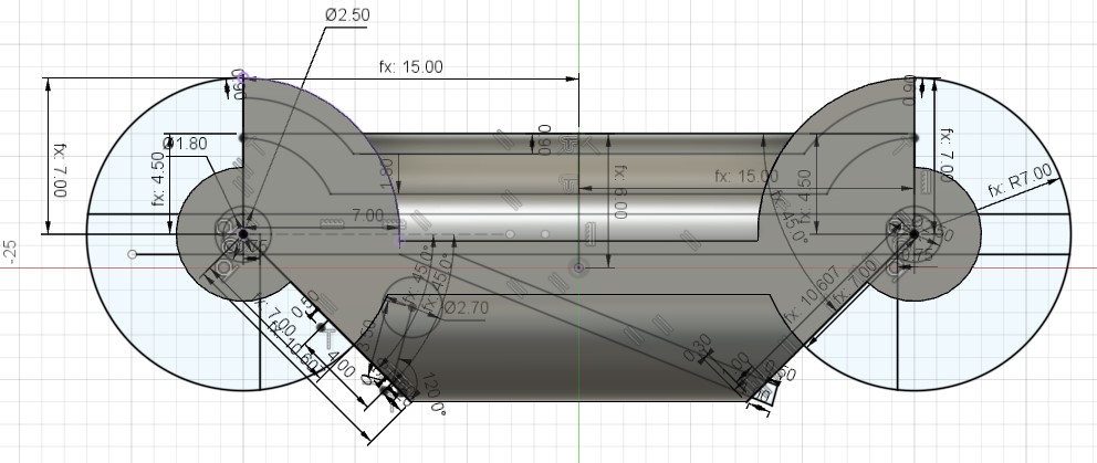
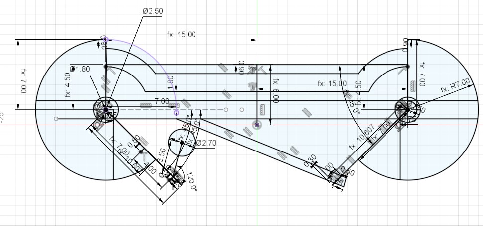
Draw this sketch and follow the features that depend on it in the following pictures
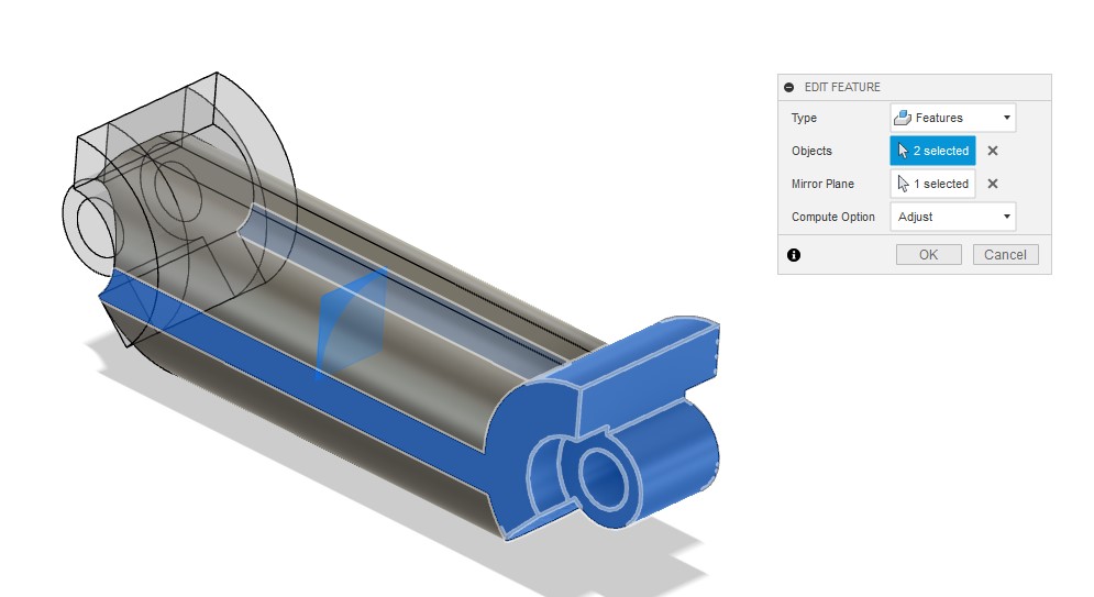
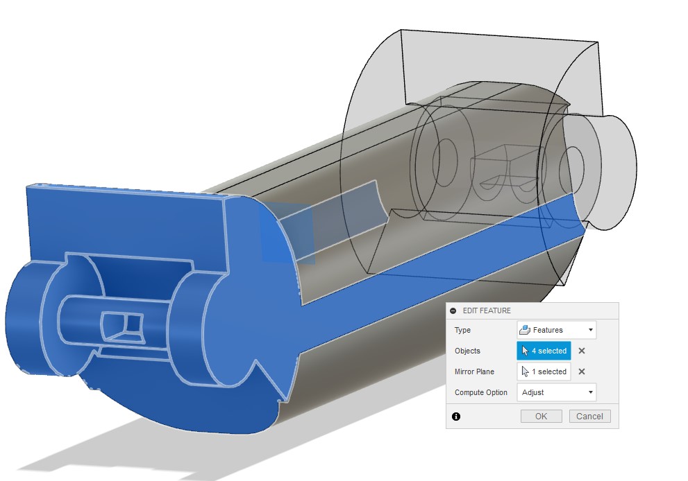
Make mirror for the previous two Feature
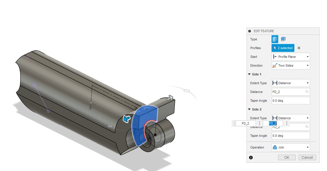
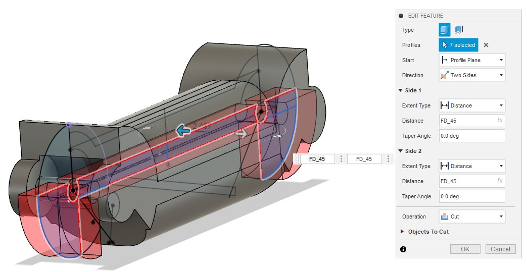
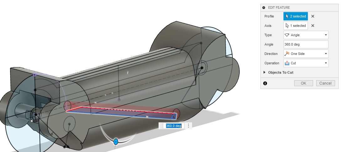
Return to the previous sketch and following the features
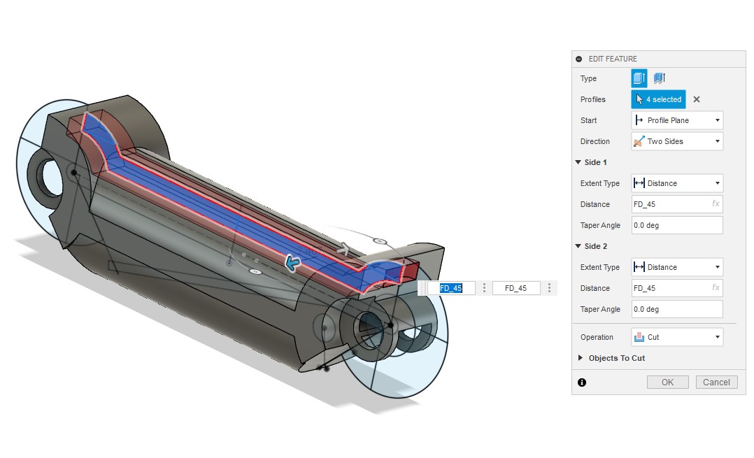
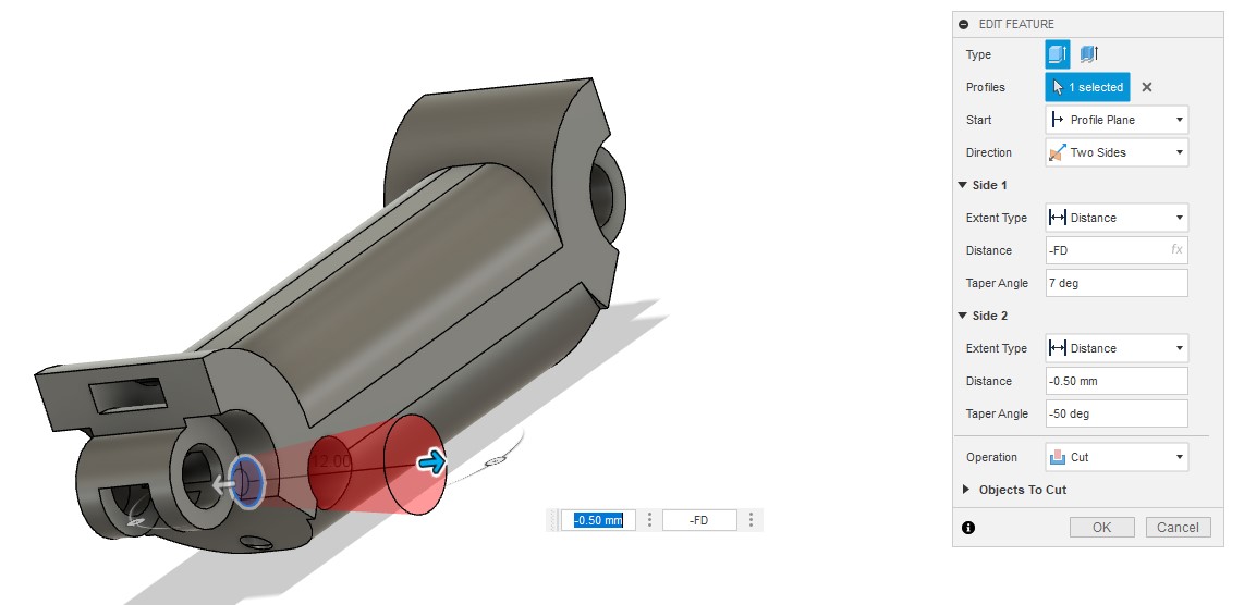
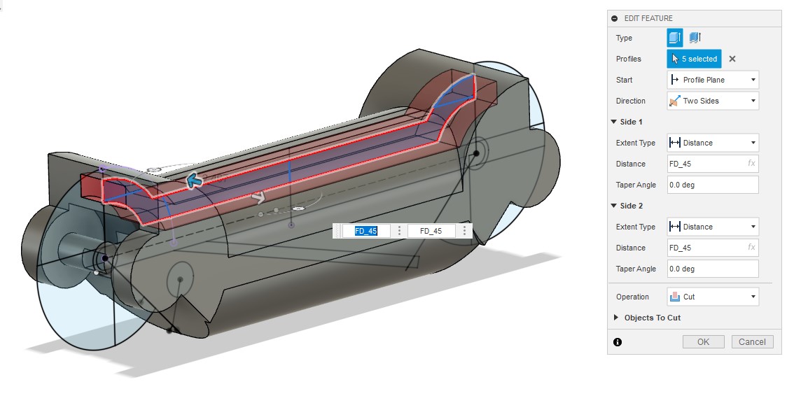
Make front section then make filet for sharp corner
Following the features
Make several copies because each finger will need an semilar piece
Start a new drawing and repeat the steps at the beginning until you reach this stage
Draw this sketch and follow the features that depend on it in the following pictures.
Make mirror for the previous three Feature
Return to the previous sketch and following the features
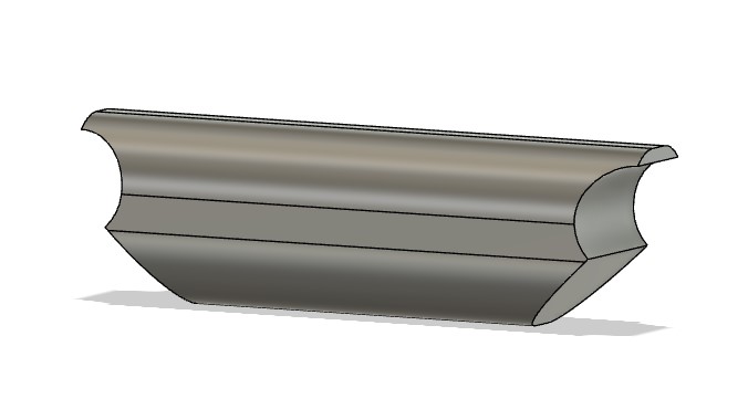
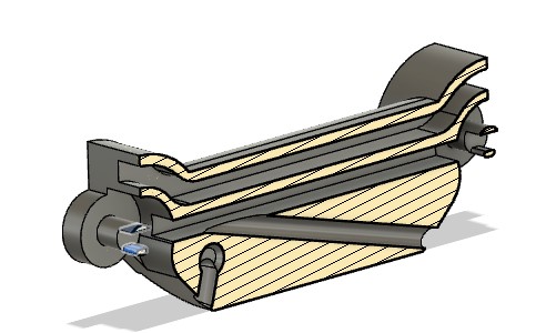
This section show the result of second part
When the previous steps are complete, the two middle pieces of the finger are ready, and we still need the ones on the ends.
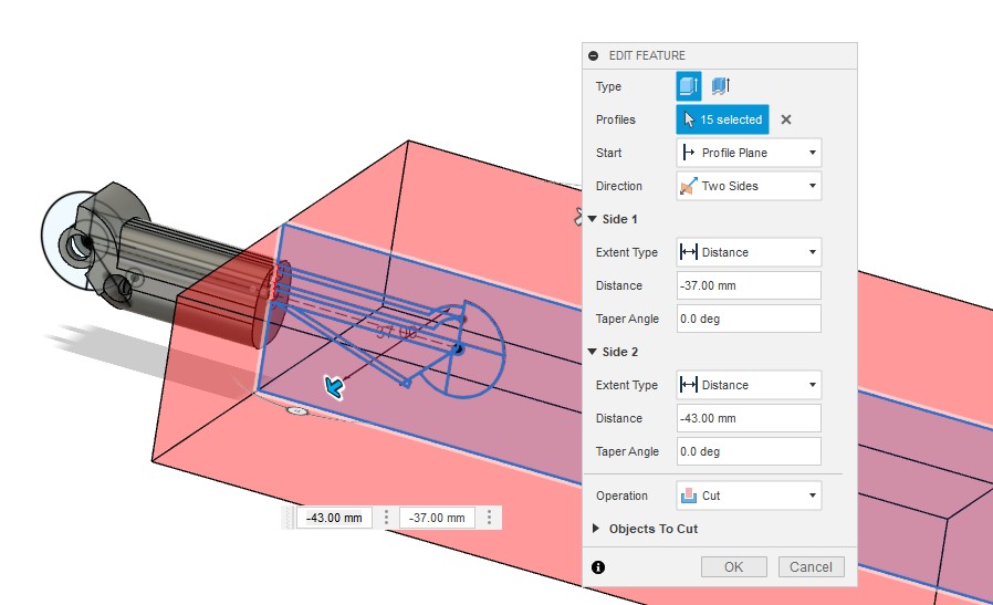
The part at the ends is similar to the halves of the previously completed parts, so we will make a copy of the first and second parts cut them in half.
Cut the first part
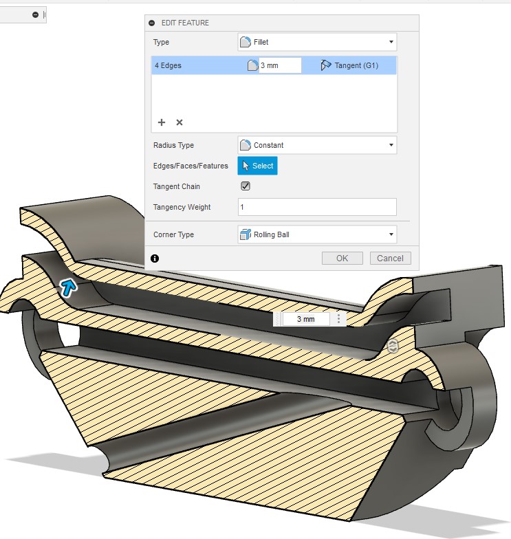
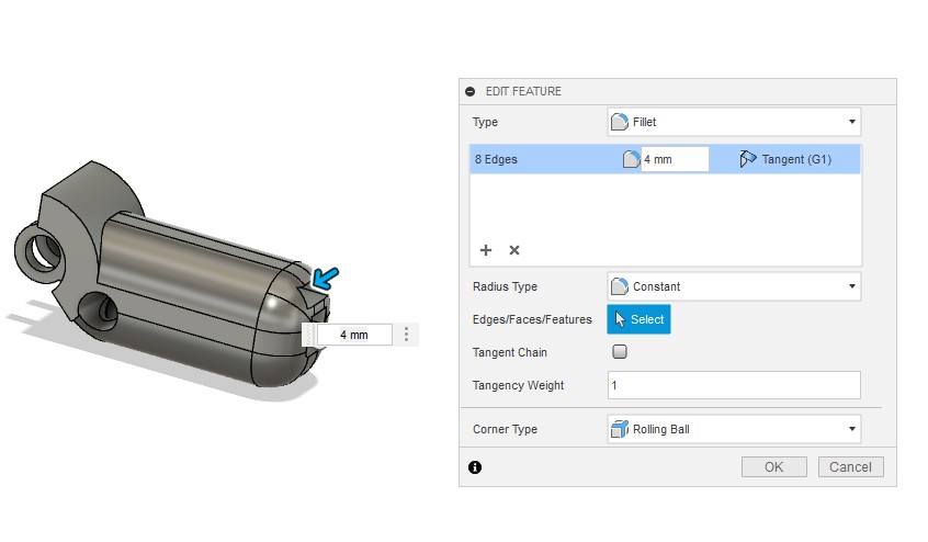
Make a fillet at cutting edge.
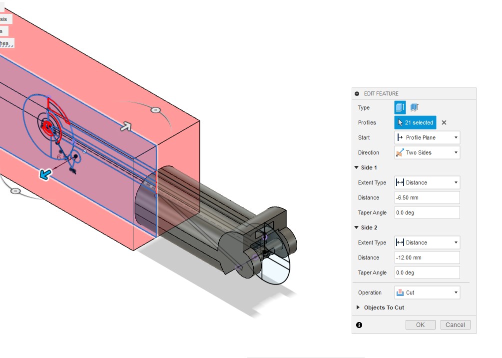
Cut the second part
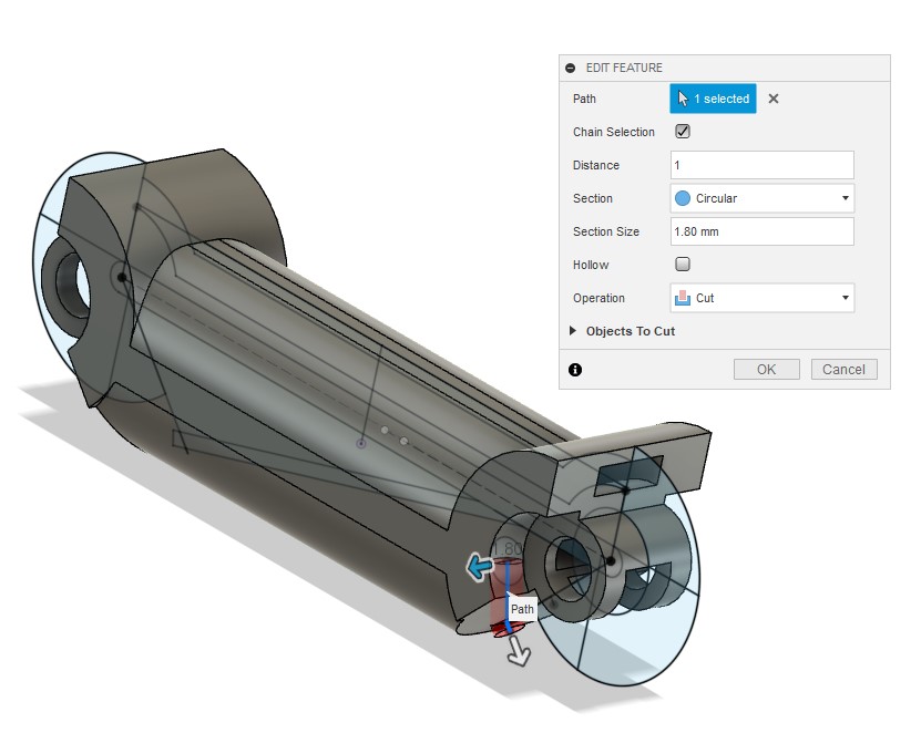
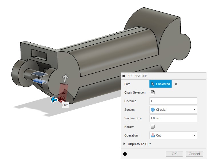
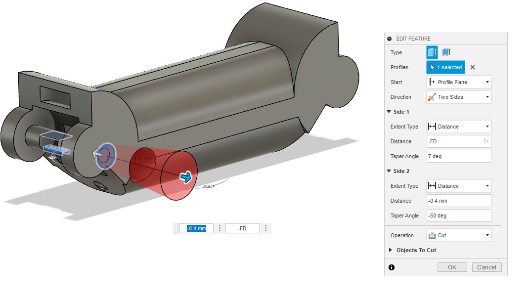
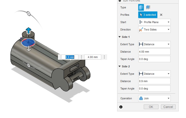
Draw a circle on the tip of the part and then extruded it. It will be used to hold the finger on the palm
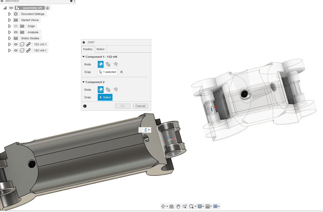
Assembly
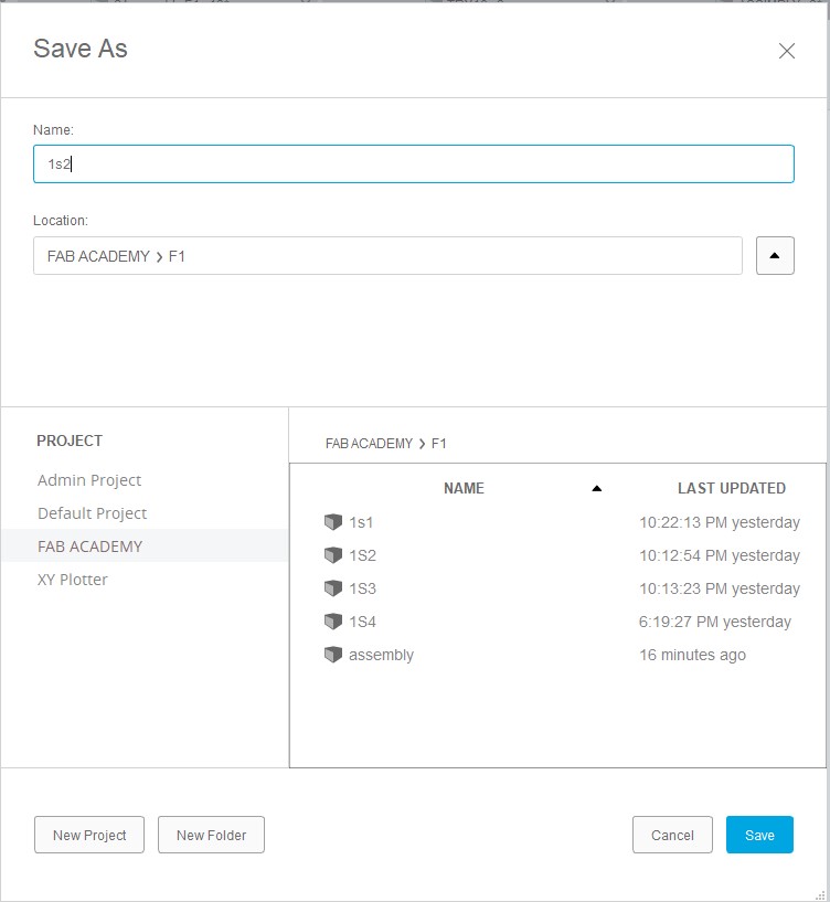
Open a new tab and save it before doing anything, import the parts of the finger, click on joint option then select the rod and cylinder after that change the type of motion from rigid to revolut.
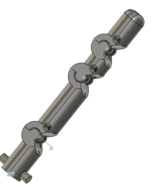
Repeat it with the fingertips to get the whole finger.
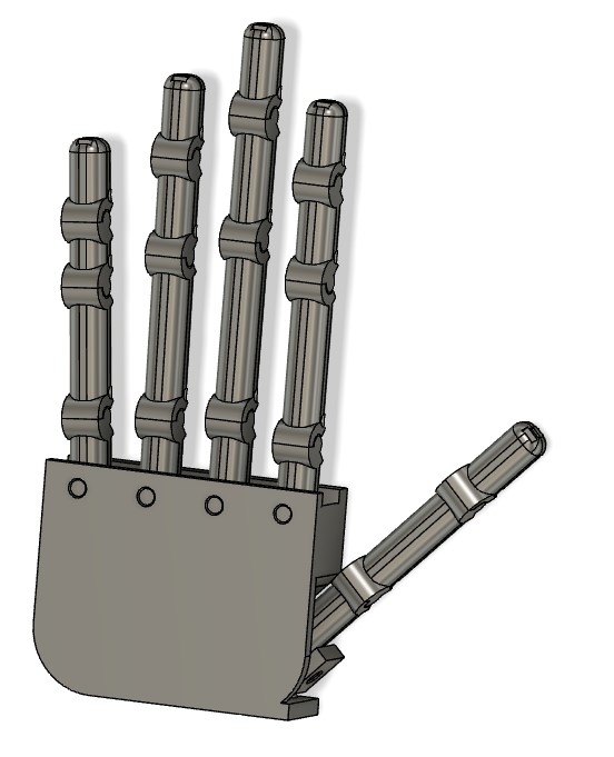
Repeat it with finger to get the whole hand.
Note: To get a different length of the finger, open the finger part and change the length of the part from the parameter.
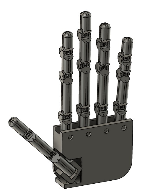
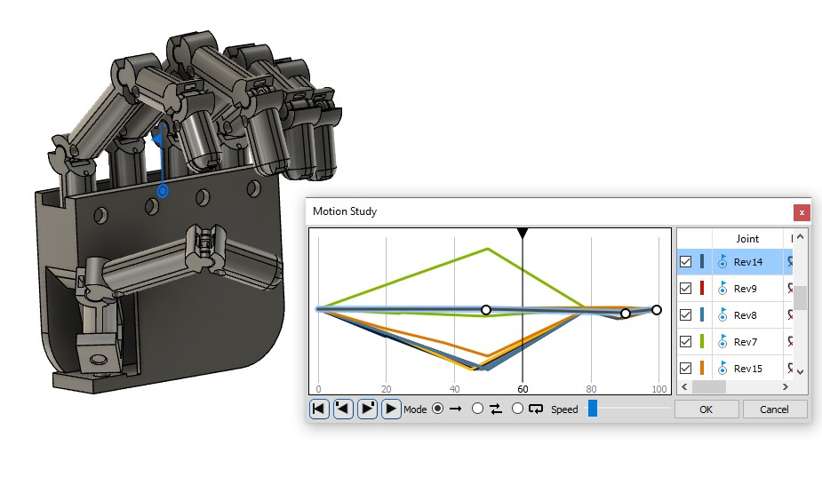
Motion
Click on option motion study from assembly list then select all joint on the hand.
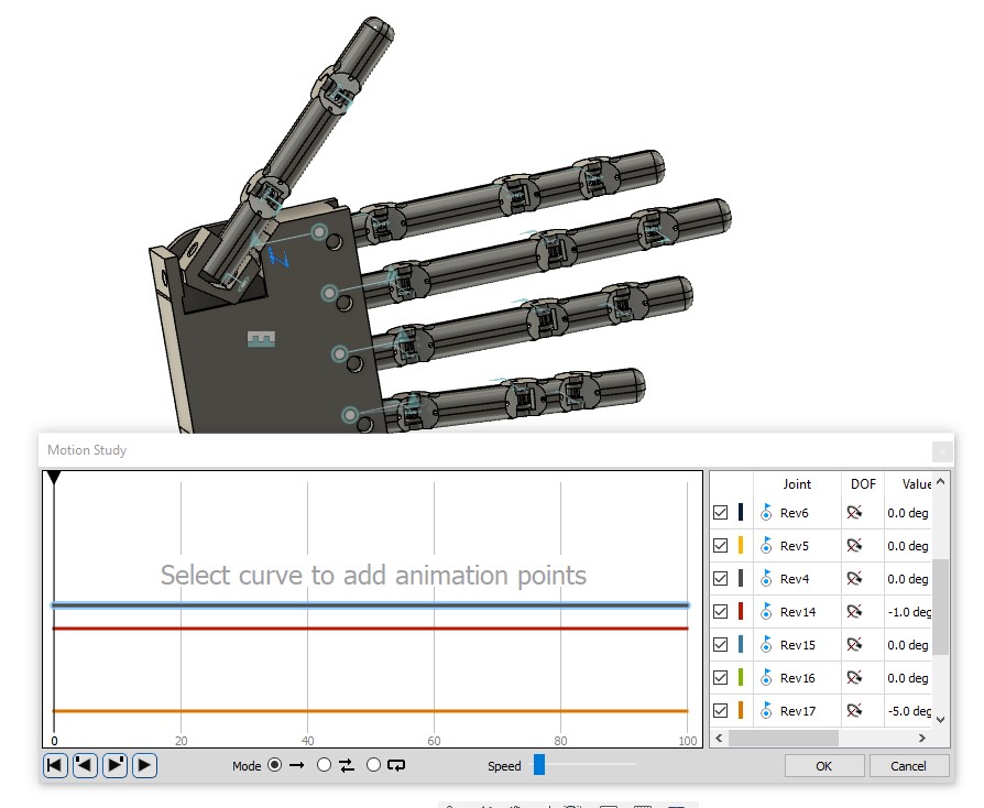
Select the joint line then make many point on it, for each point choose the steps and angle that make the hand in right position.
Render
Go to Render section , click on Appearance and choose multi material from fusion library then drag and release the material on the required part.
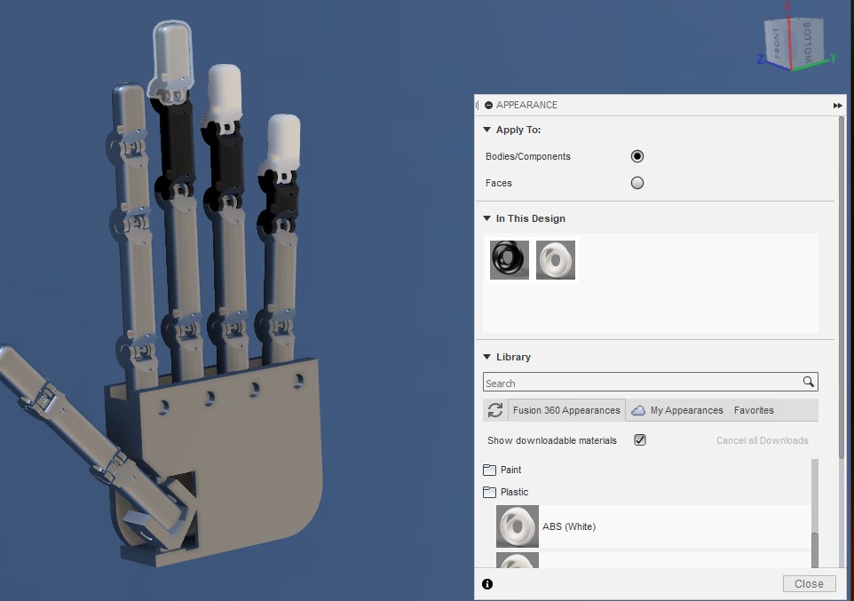
This is how it looks when you choose the appearance for all the part.
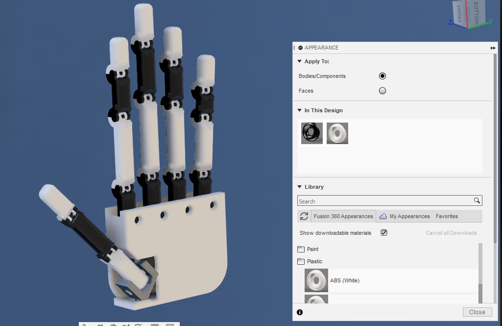
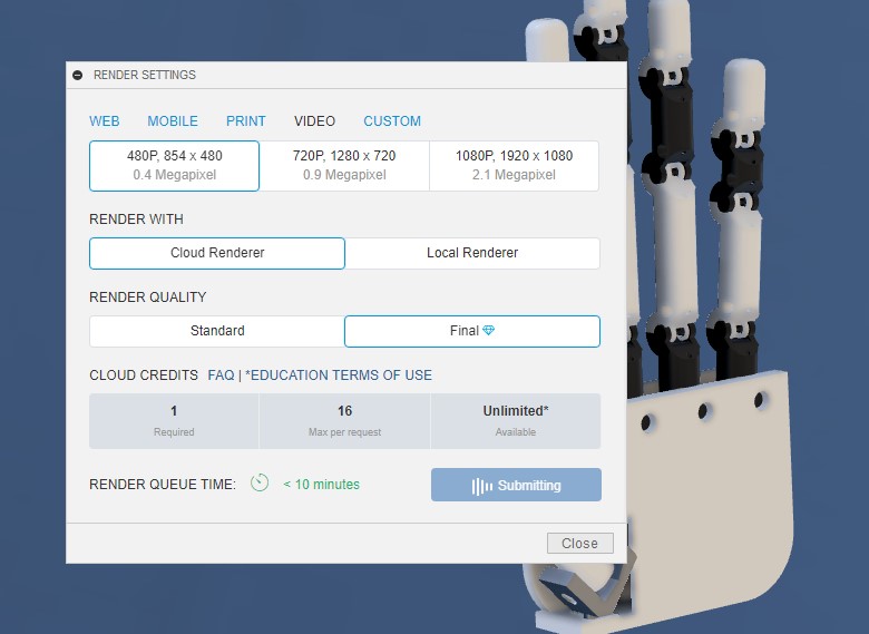
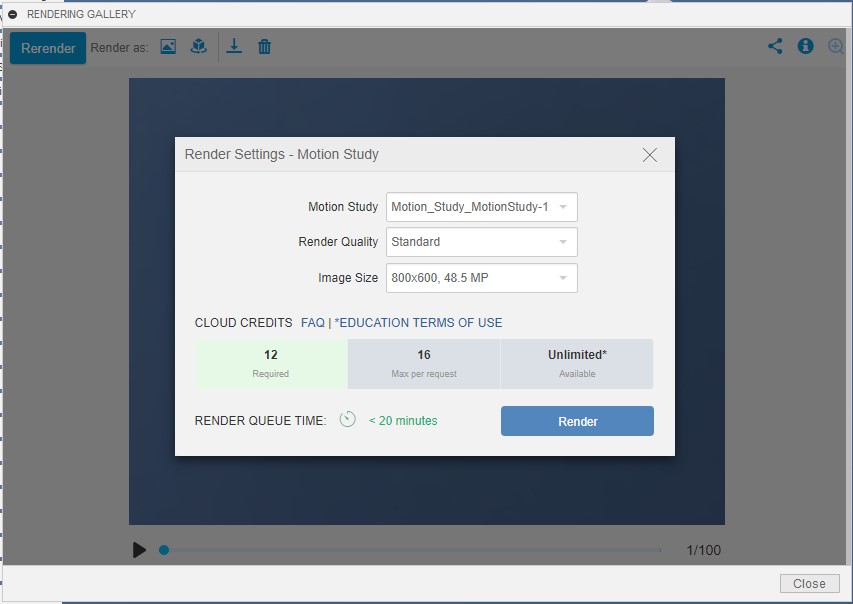
Choose video render then select the size, resolution and study motion, finally click on Render
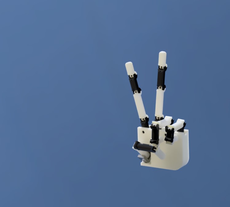
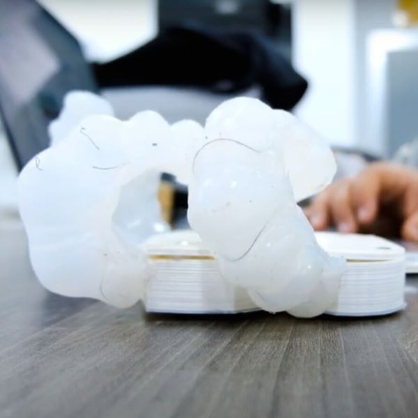
Rusalt
Generative design
File to Download
3D Model for Dron
At the beginning of this week, I wanted to do something special and at the same time learn something new so I decided to create a design using Generative design.
"Generative design is a design exploration process. Designers or engineers input design goals into the generative design software, along with parameters such as performance or spatial requirements, materials, manufacturing methods, and cost constraints. The software explores all the possible permutations of a solution, quickly generating design alternatives. It tests and learns from each iteration what works and what doesn’t."
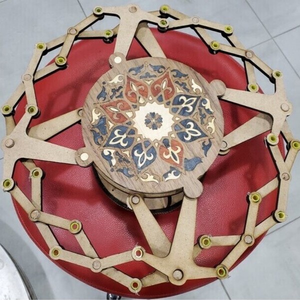
The most important advantage in generative design is to generate a design so that it has the highest stiffness and least weight, and one of the best examples of our great need for it is the drone, so we will generate a design for the drone.
Starting by designing the frame.
Draw a square and extruded it 4 mm.
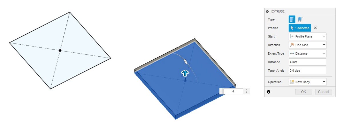
Make an offset plan, the offset 40mm .
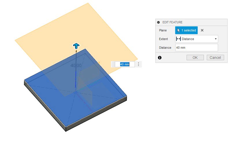
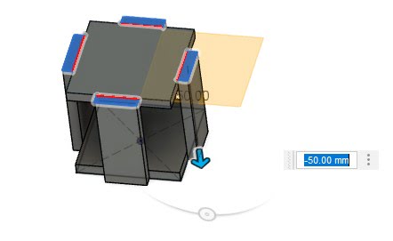
Draw same square and extruded it 4 mm.
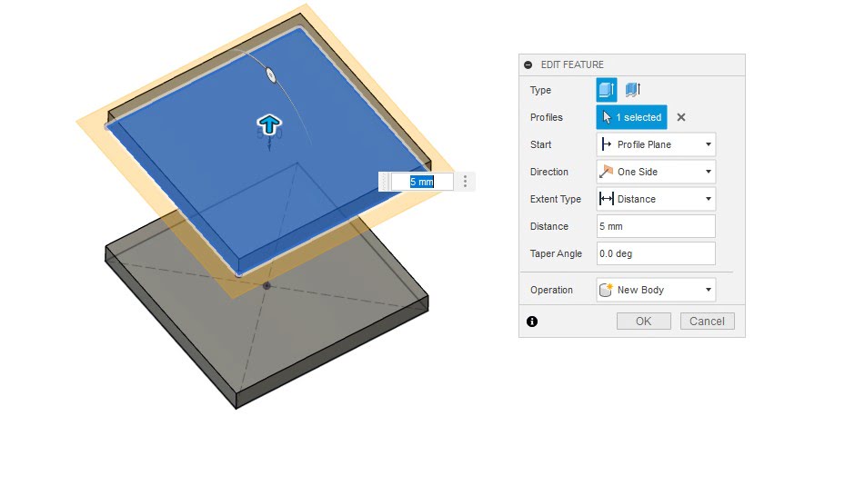
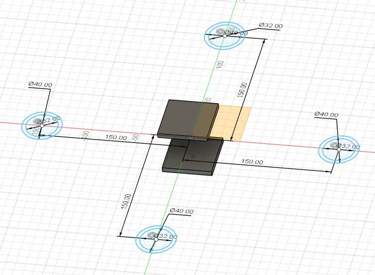
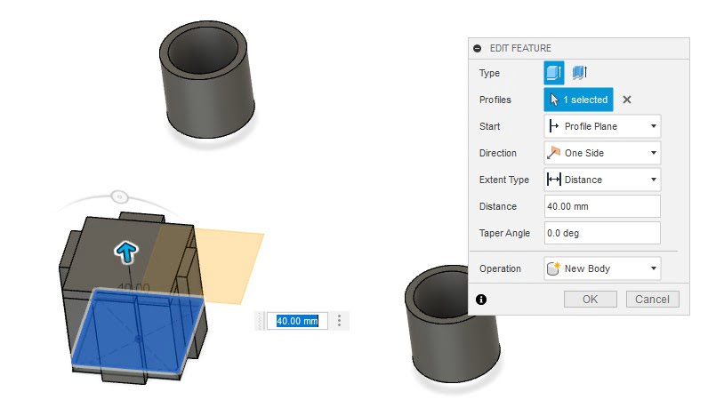
Make an offset plan, the offset 20mm and draw four hollow cylinders like picture.
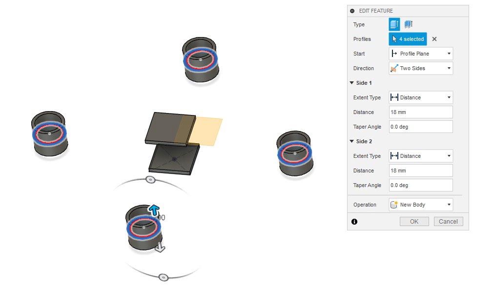
Extruded the hollow cylinders from two side as new body .
Draw four rectangles and Extrude it as new body.
Draw square and extruded covers the middle area.
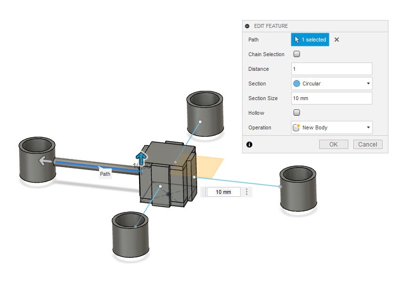
Draw four line and make it pipe as new body.
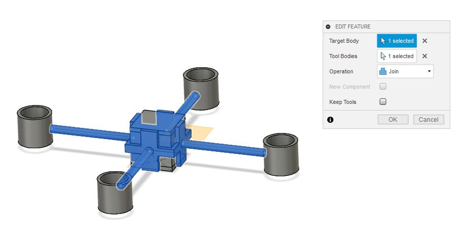
Combine the bodys in the picture.
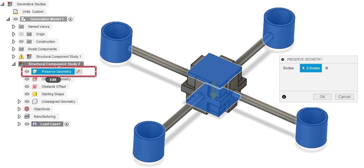
Go th Generative design section and select Preserve geometry as picture.
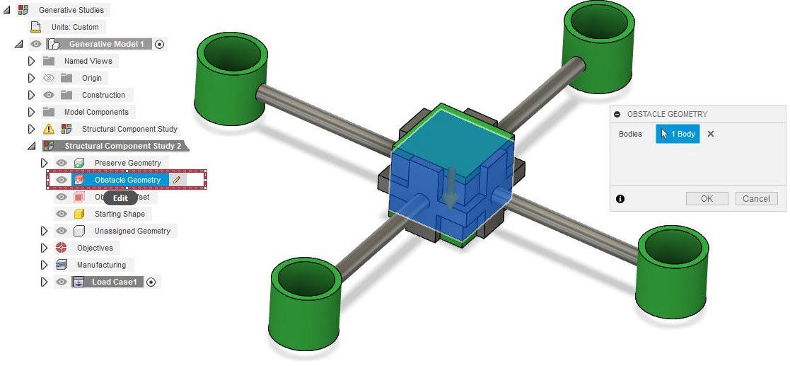
Select Obstacle geometry as picture.
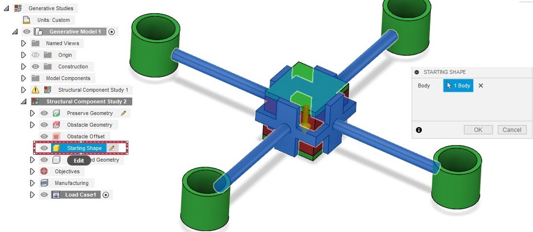
Select Starting geometry as picture.
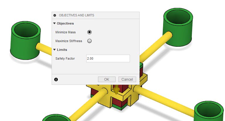
Click on objectives and select minimize mass and safety factor.
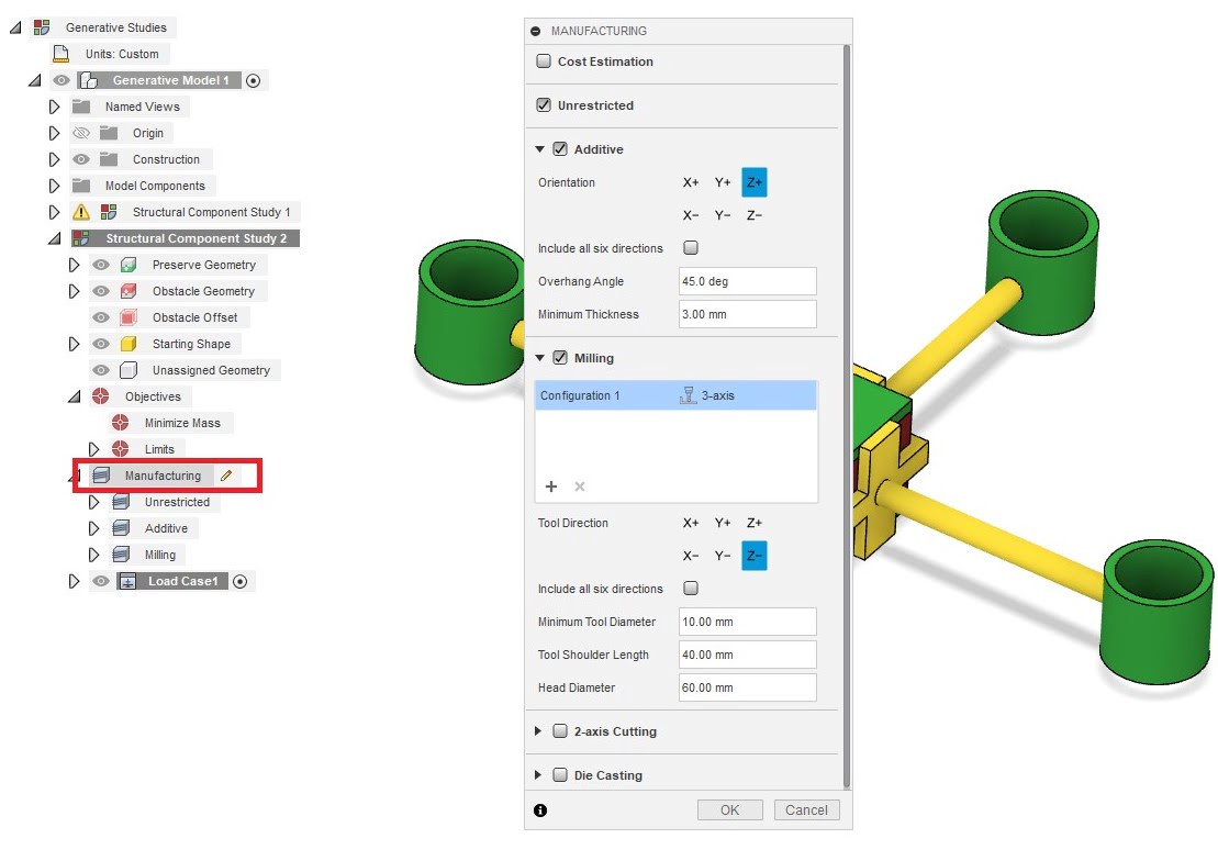
Click on manufacture and select manufacture mothod.
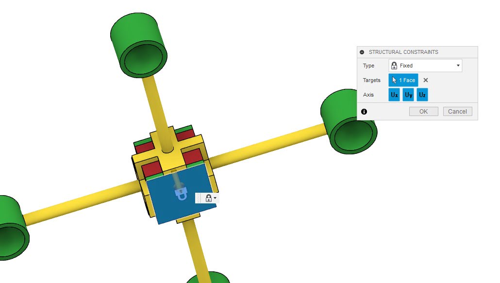
Click on structural constraint and select fixed for bottom surface.
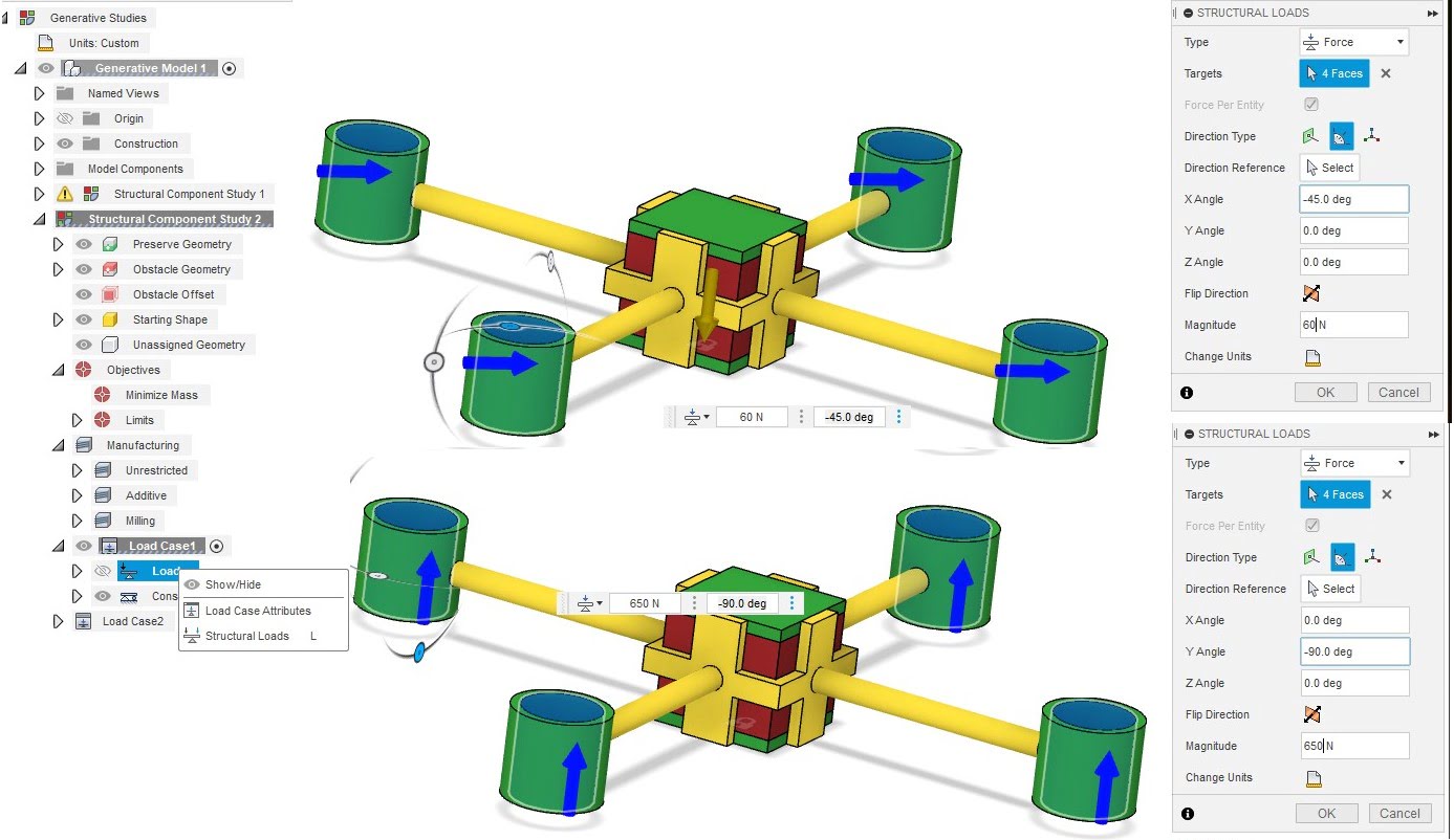
Click on structural load and select cylinder bore, Note:There are two cases of load.
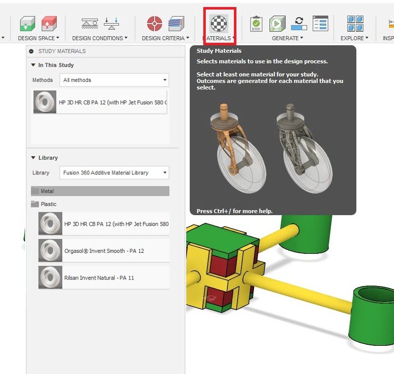
Click on stady material and select the material.
Cheak.
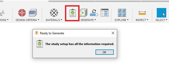
Finally generate.
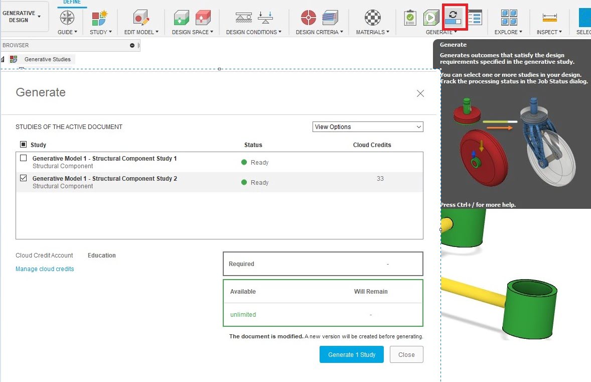
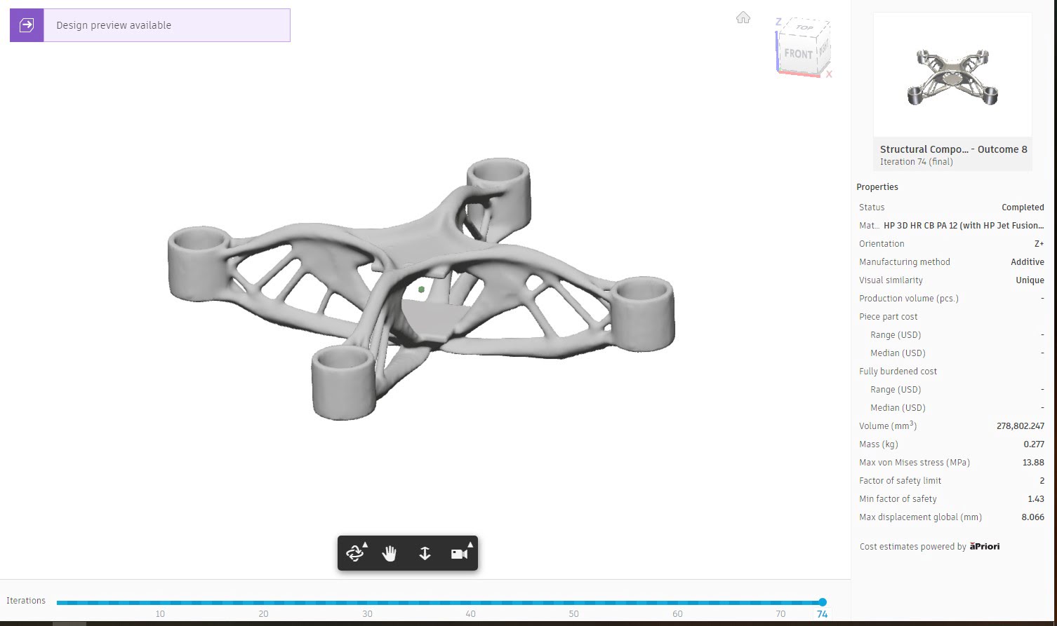
To see the results Click on Explore.
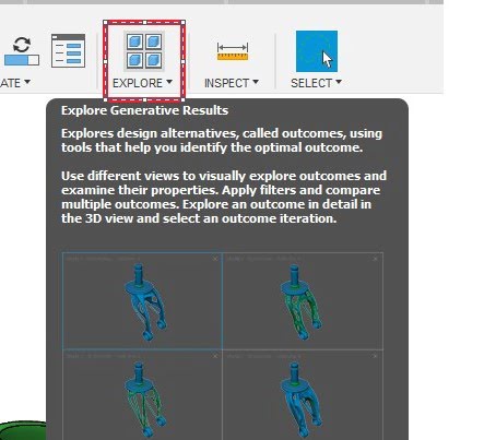
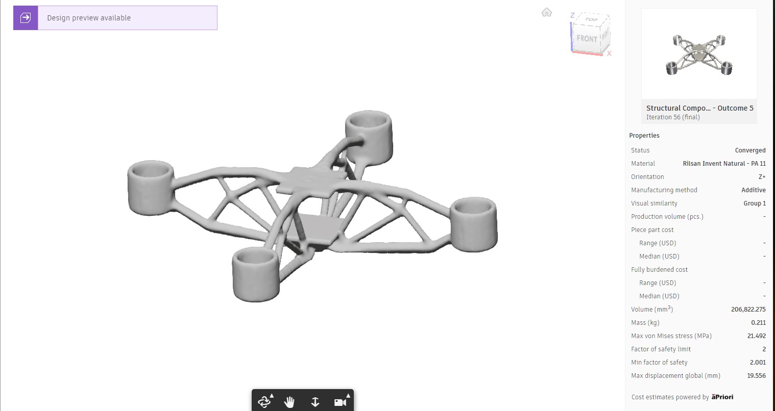
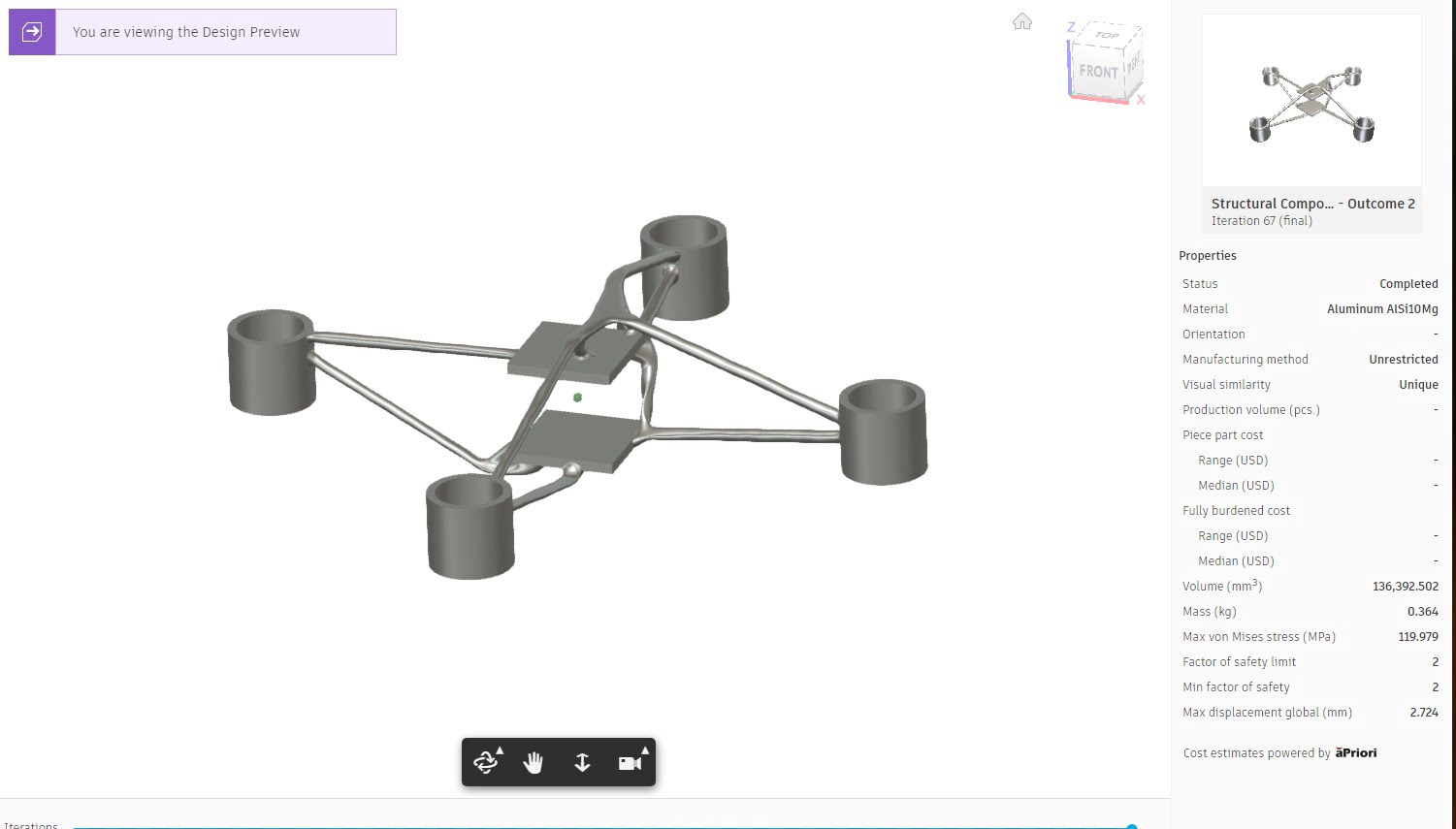
The results can be displayed in a variety of ways.
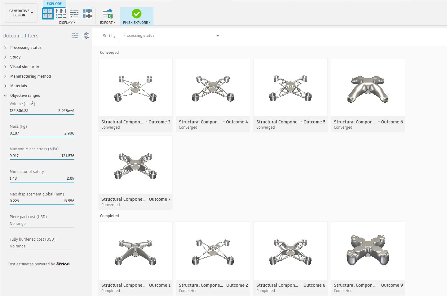
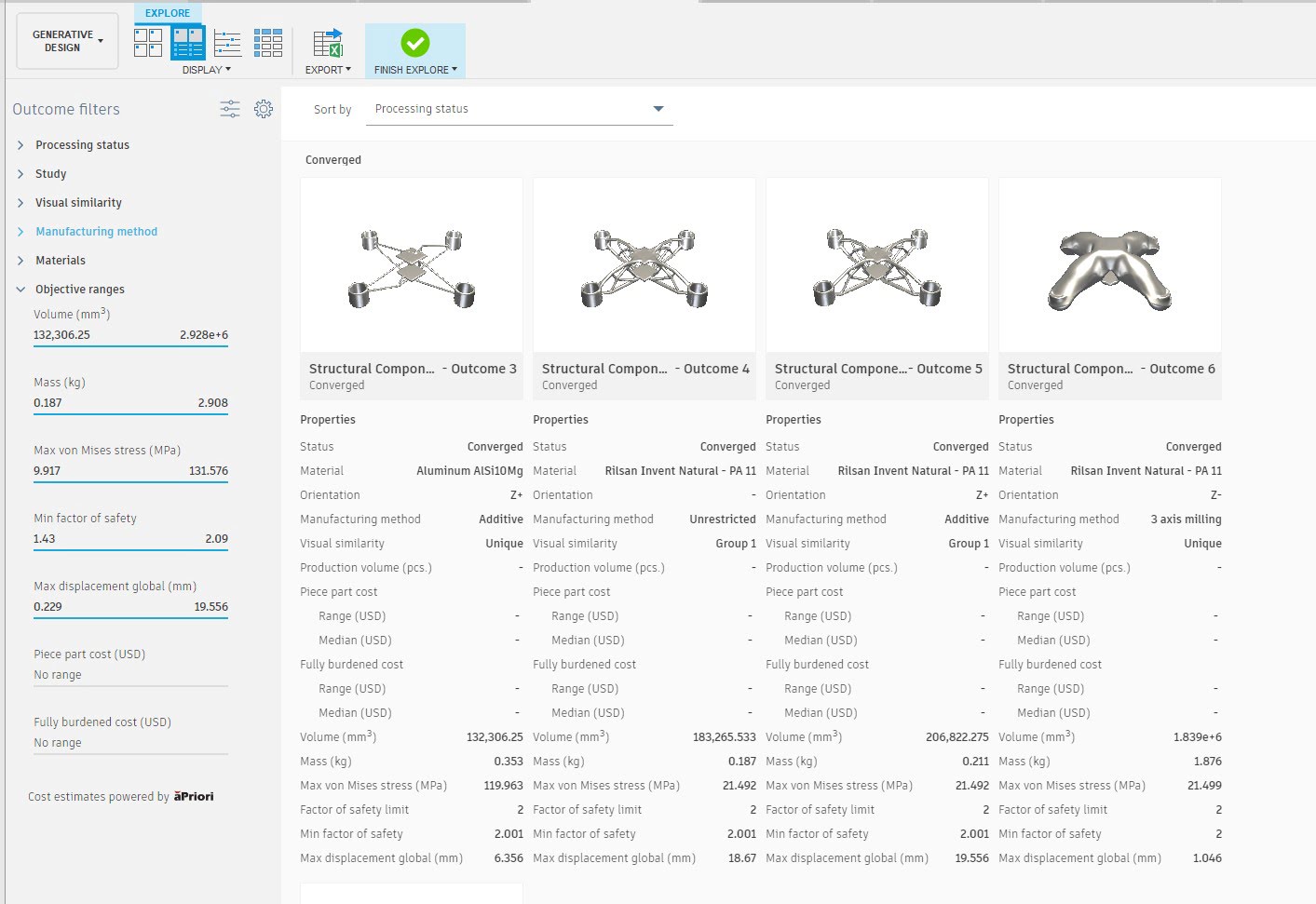
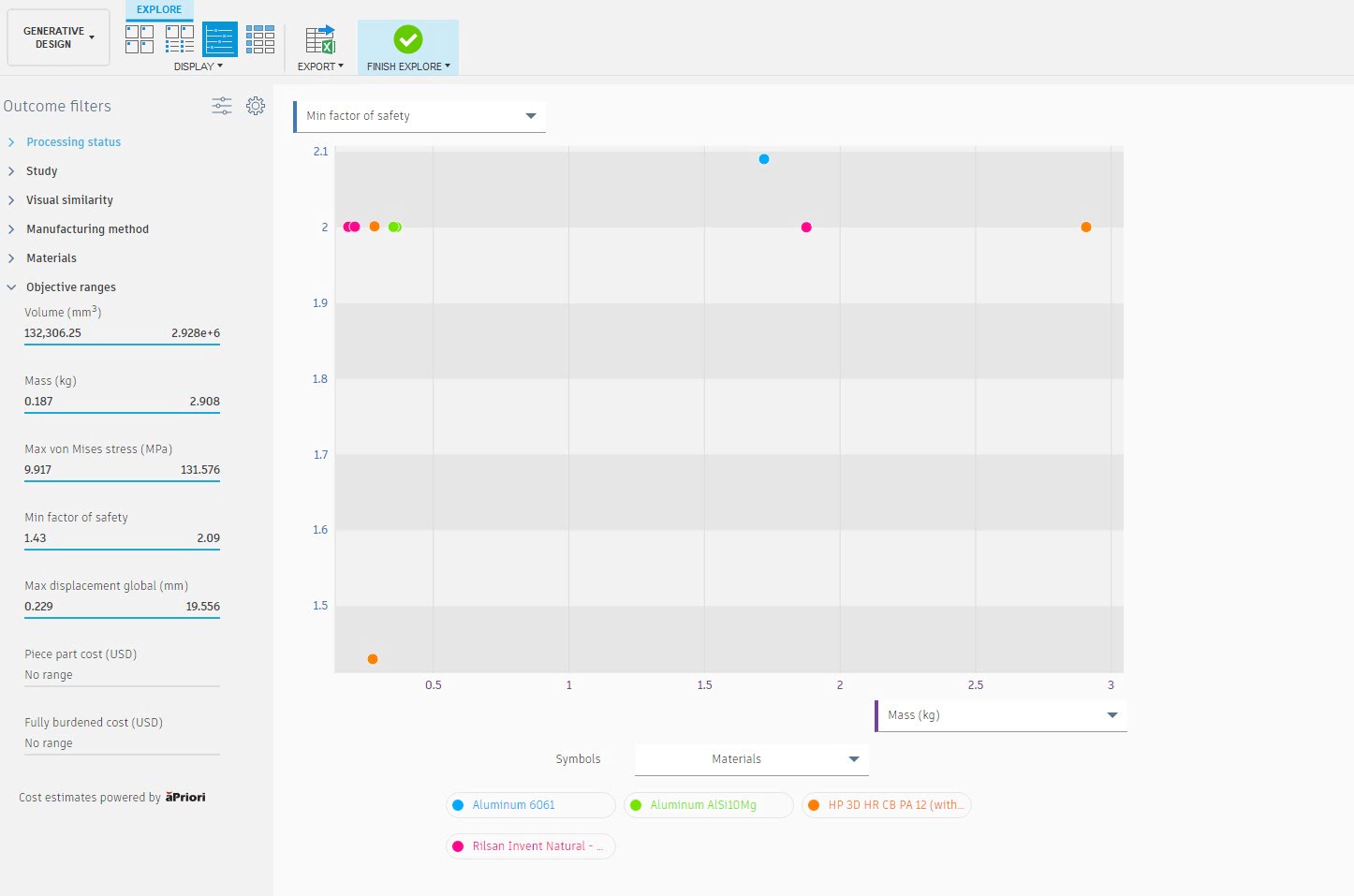
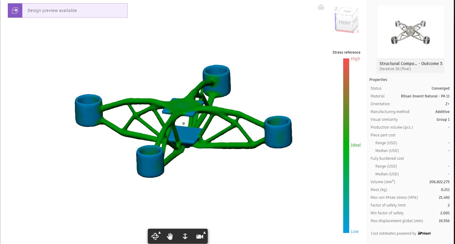
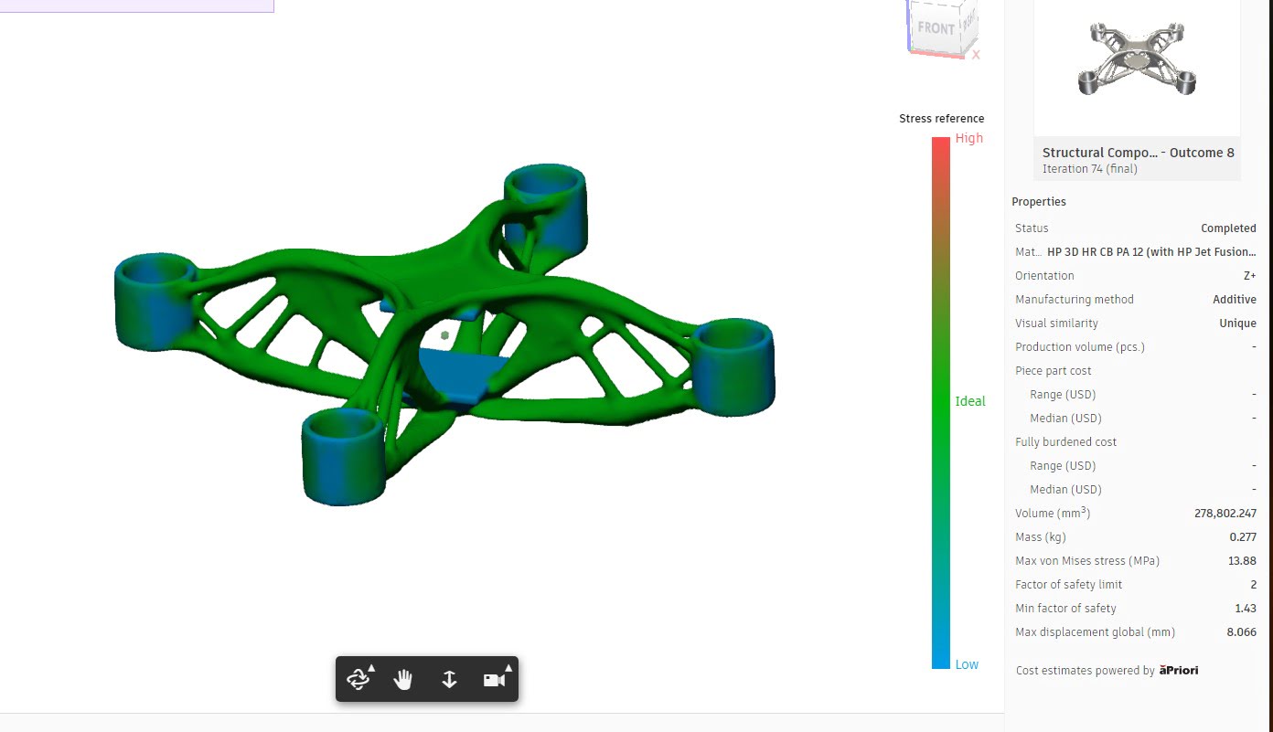
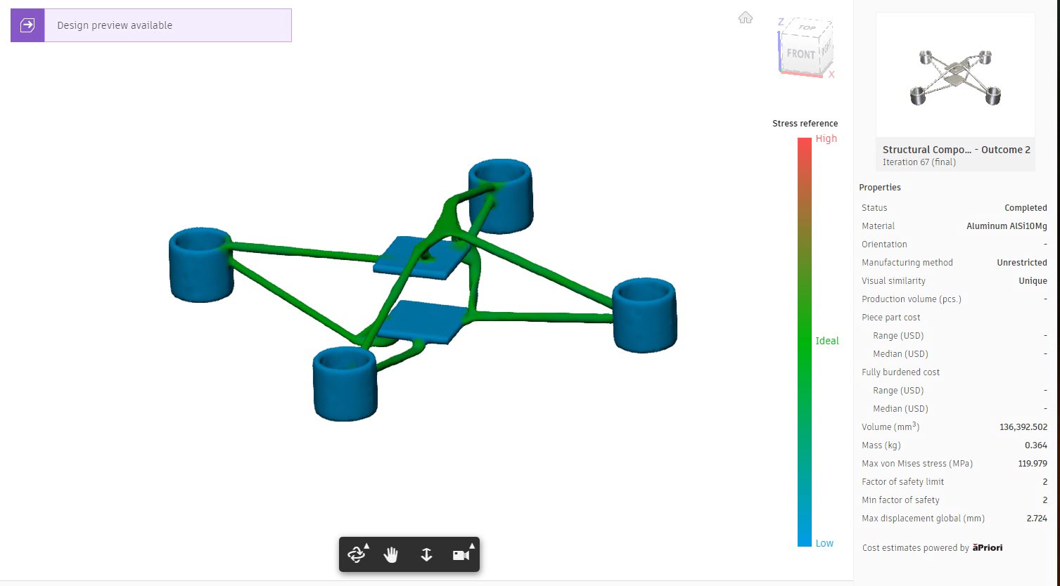
The best results and the distribution of the load in it


