Input devices
Group Assignment
-Probe an input device(s)'s analog and digital signals.
-Document your work to the group work page and reflect on your individual page what you learned.
Digital Signal
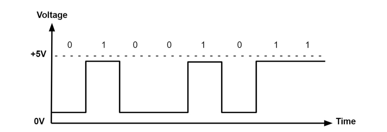
A digital signal is one in which data is represented as a series of discrete values. At any one time, a digital signal can only take on one value from a finite set of possible values. The physical amount representing the information in digital signals can be any of the following:
-Electric current or voltage that varies.
-Phase or polarization of an electromagnetic field.
-Acoustic pressure.
-The magnetization of a magnetic storage media.
All digital electronics, including computing equipment and data transmission devices, employ digital signals. Digital signals have one of two values when plotted on a voltage vs. time graph, and are normally between 0V and VCC (usually 1.8V, 3.3V, or 5V)
Source
Encoder
The rate of an electric motor may be checked using this Encoder Sensor Module Digital Output. This module may be used in conjunction with a microcontroller to detect motor speed, count pulses, and set a position restriction. Any rate meter, in theory, merely monitors the rate at which an event occurs. Typically, this is accomplished by counting the events over a specified time interval (integration interval) and then dividing the number of events by the duration to obtain the rate.Source
We tested the level of a encoder When the infrared light is cut off and when it is connected in this section. The encoder (usually low) is connected to Vcc= 5 V ,GND and output signal. the output signal is 0 V level in its normal condition (digitally low). The level will be 1 V when the infrared light is cut off (digitally high).
Analog Signal
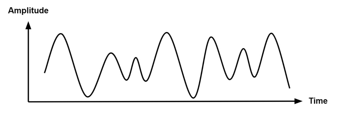
An analog signal is time-varying and often limited to a range (e.g., +12V to -12V), although it can take on an infinite number of values. An analog signal, such as electricity travelling over a wire, employs a specific property of the medium to convey the signal's information. To represent information in an electrical signal, the voltage, current, or frequency of the signal can be changed. Analog signals are frequently calculated reactions to variations in light, sound, temperature, position, pressure, and other physical phenomena.An analog signal should generate a smooth and continuous curve when plotted on a voltage vs. time graph. There should be no abrupt fluctuations in value.
Source
Potentiometer
A potentiometer is a type of position sensor. it used to determine how far something has moved in any direction. Rotary potentiometers measure rotational displacement whereas linear potentiometers measure linear displacement.
Source
We tested the signal of a Potentiometer When we rotate it in this section. The Potentiometer is a variable resistance according to its rotation, resulting many voltages as output signal.
2. Individual Assignment
Measure something: add a sensor to a microcontroller board that you have designed and read it.
2.1. ATmega328P Development Board
File to Download
Eagle file
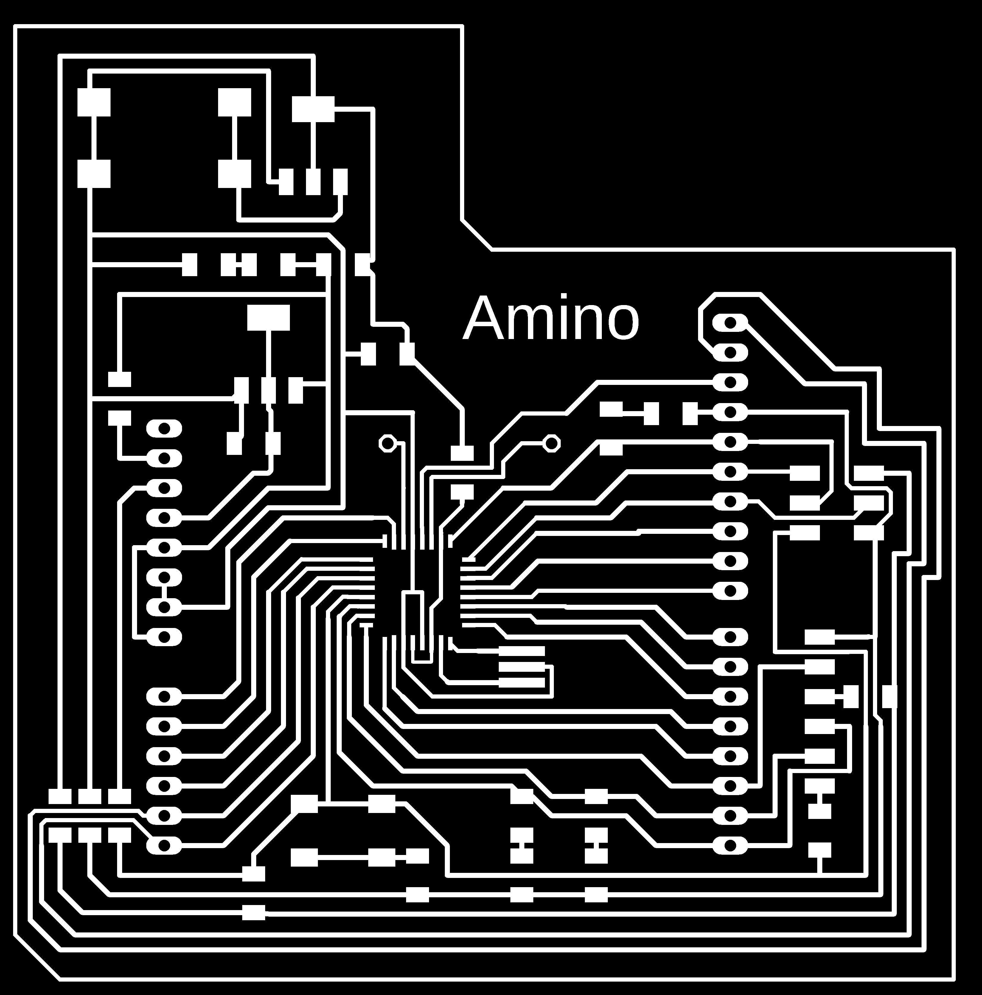
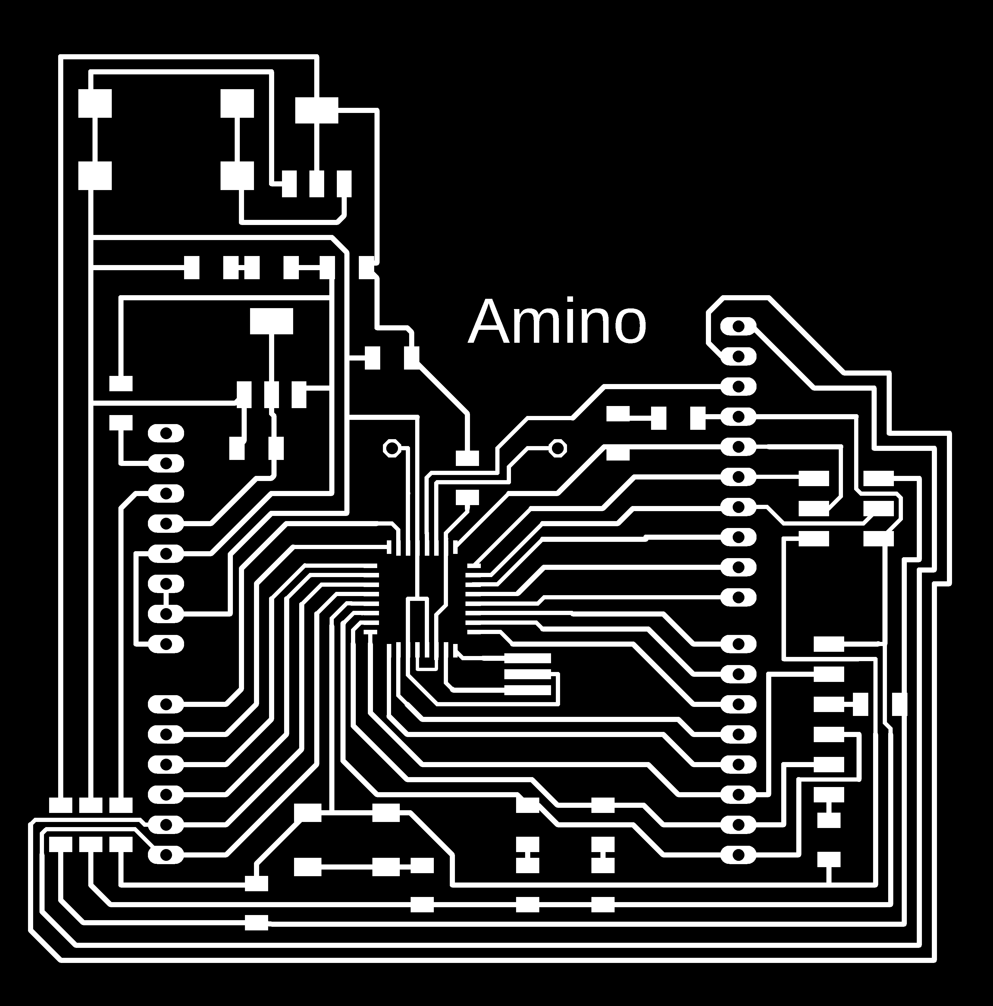
Trace.png
Trace.rml
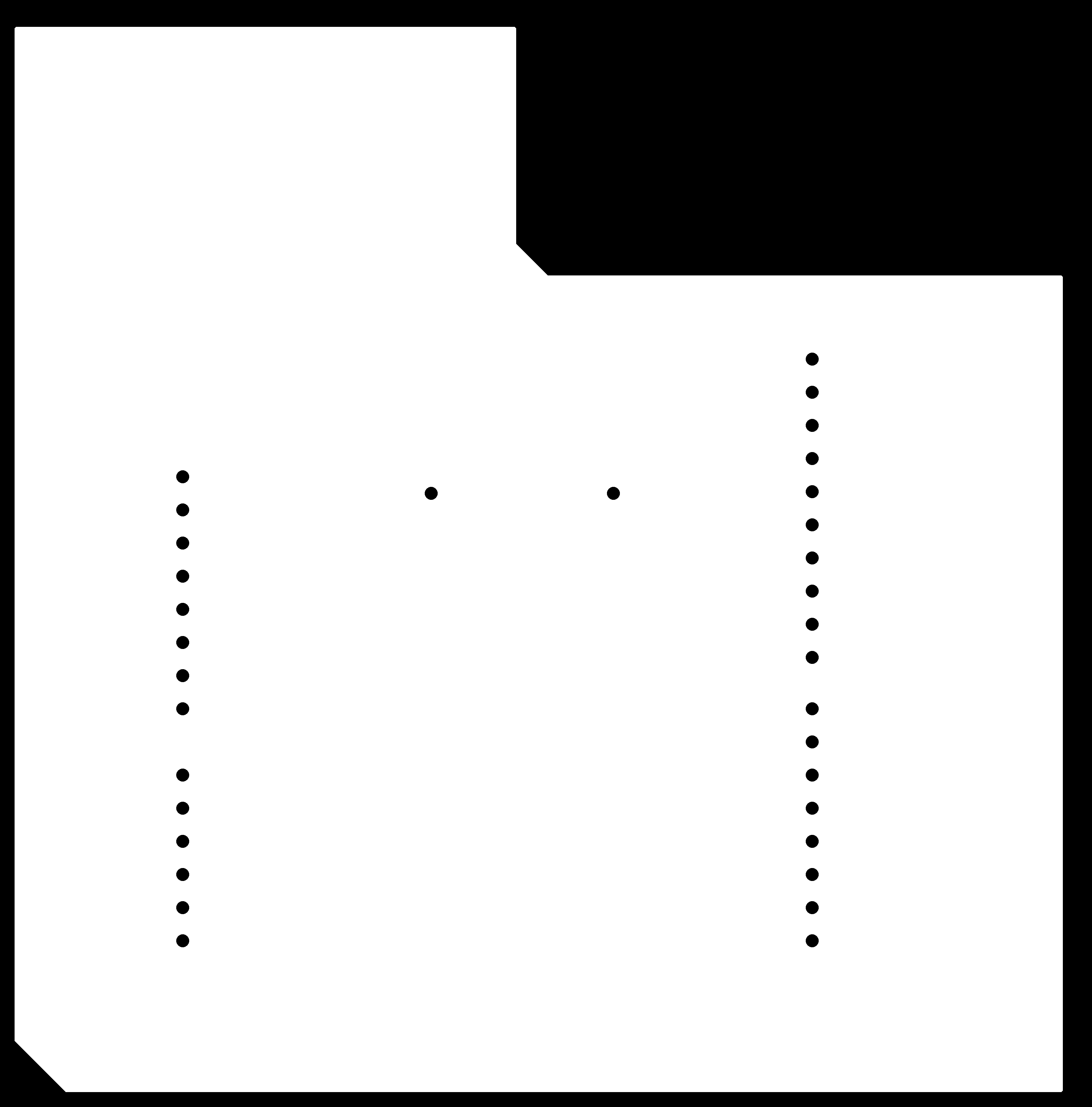
Outline.png
Outline.rml
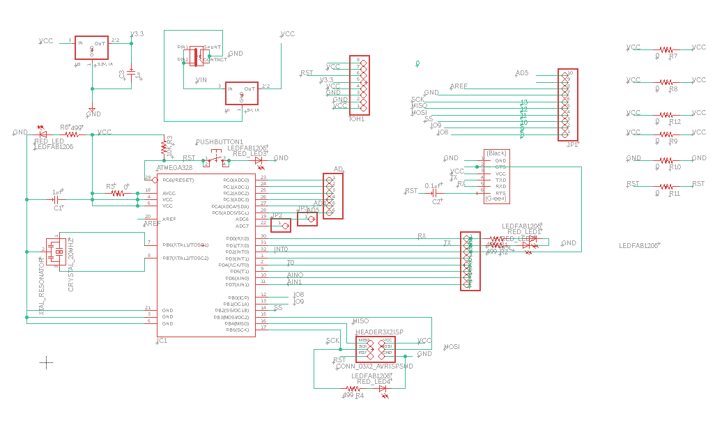
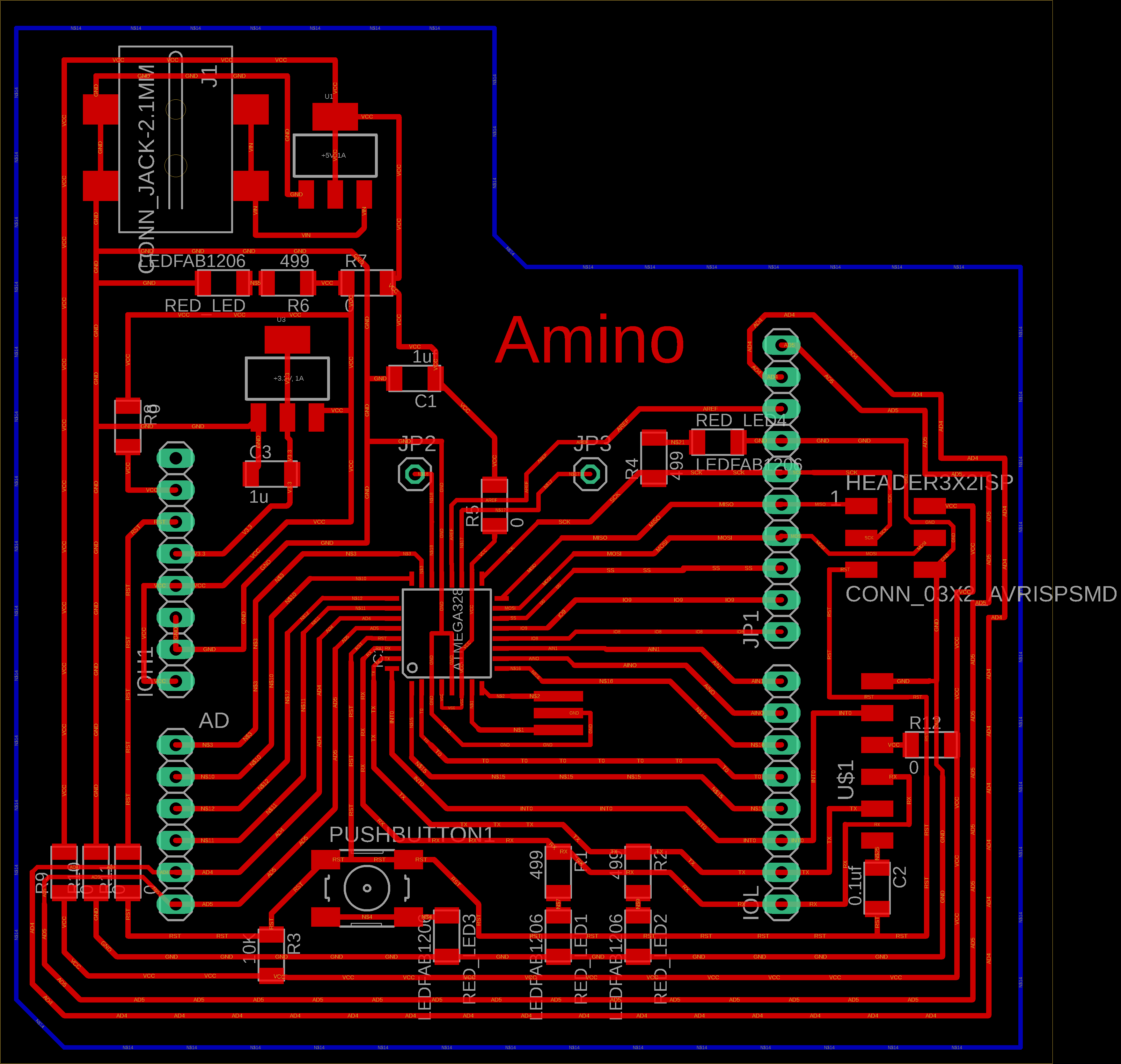
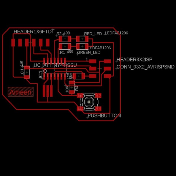
The figure below shows the schematic diagram of the board, which consists mainly of atmega 328 micro controllar, pin header and crystal 20 MHz. The table below the picture shows the components of the board.
| Description | Reference | Lib Name | Quantity |
|---|---|---|---|
| ATMEGA328 | IC1 | TQFP32-08THIN | 1 |
| CRYSTAL_20MHZ | CRYSTAL_20MHZ | EFOBM | 1 |
| Header 3x2 ISP | HEADER3X2ISP | CONN_03X2_AVRISPSMD | 1 |
| Header 1x6 FTDI | U$1 | CONN_06_FTDI-SMD-HEADER | 1 |
| Capacitor unpolarized 1uF | C1 | CAP_UNPOLARIZEDFAB | 2 |
| Capacitor unpolarized 0.1uF | C2 | CAP_UNPOLARIZEDFAB | 2 |
| Resistor 499 Ohm | R1&R2&R4&R6 | R1206FAB | 1 |
| Resistor 0 Ohm | R5&R7&R8&R9 &R10&R11&R12 |
R1206FAB | 1 |
| Resistor 10kOhm | R3 | R1206FAB | 1 |
| RED_LED | RED_LED | LEDFAB1206 | 2 |
| blue_LED | blue_LED | LEDFAB1206 | 2 |
| yellow _LED | yellow_LED | LEDFAB1206 | 2 |
| JACK | J1 | PJ-002AH-SMT | 1 |
| Voltage regulator 3.3V | U2 | SOT223 | 1 |
| Voltage regulator 5V | U1 | SOT223 | 1 |
| PUSHBUTTON | PUSHBUTTON | 6MM_SWITCH | 1 |
| pin header 1X1 | JP2&JP3 | R1206FAB | 2 |
| pin header 1X6 | AD | R1206FAB | 1 |
| pin header 1X8 | TOH1 | R1206FAB | 2 |
| pin header 1X10 | JP1 | R1206FAB | 1 |
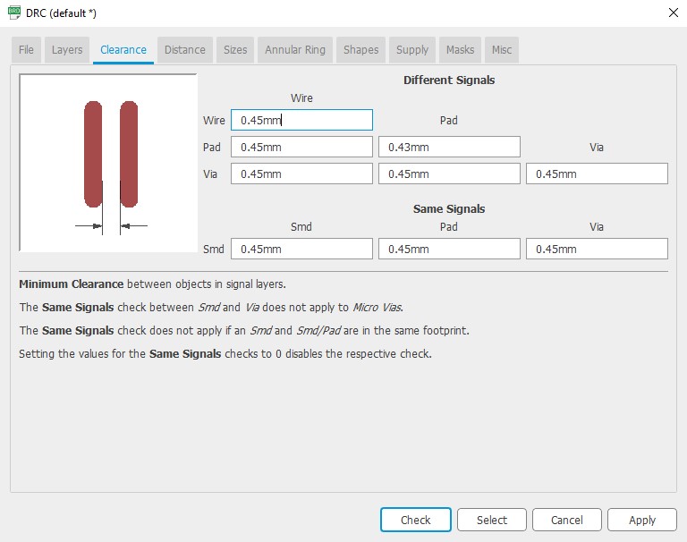
Before starting tracing, the design roles should be defined as below to avoid short circuit when milling the board. For more details Electronics design


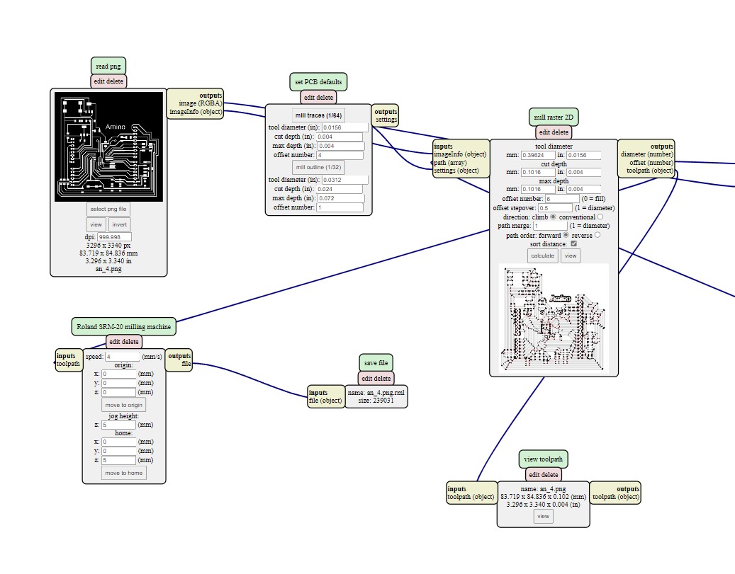
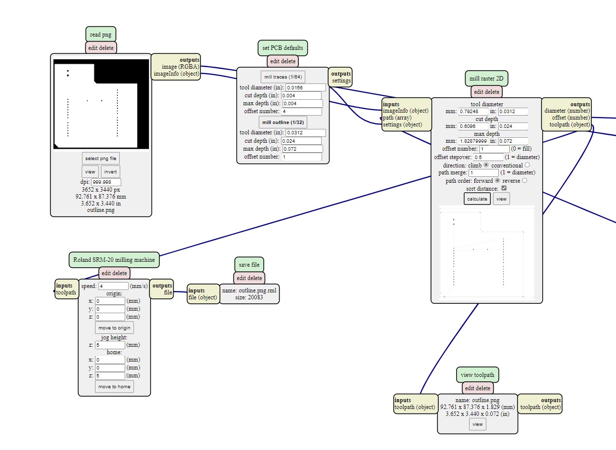
Mods
Step 1: Open Mod and Right click any whare. select programs - open server program - PCB png from Roland SRM-20 list.
Step 2: On the “read png” block Click on select png file and choose the "trace.png"
Step3: Select mill trace from “set PCB defaults” block.
Step4: On the “Roland SRM-20 milling machine” block let the origin coordinates 0,0,0
Step8: Right click and select modules - open server module- save.
Step9:- replace "websocte device" block with "save file" block .
Step10:- Click on calculate in "mill raster 2D" block , The RML file will be downloaded automatically.
Note : you can have better finish if you make the offset more than 4 like 6 but it will take more time.
Step11:Repeat the previous steps on the outline.png file, but click on the mill outline rather than mill traces from set PCB defaults block , to have outline.rml file
Note: check the job dimention before calculate.
VPanel for SRM-20 software (PCB)
Now we can mill and cut the board design using the rml files. first of all we must identify the mill bit's origin.
Step 1: Open the VPanel program and go to the dropdown menu and pick "Machine Coordinate System."
Step 2: move the head over the bottom left corner of the PCB, use the arrows in red box. then raise the head , use the "+Z" arrow to create enough space between the spindle and the PCB.
Step 3: Install the 1/64" milling bit in the spindle collet, keeping roughly 25% of its length outside.
Step 4: Using the "-Z" arrow, lower the spindle until the distance between the PCB and milling bit tip are about 5 mm . Untie the fastening screw while holding the milling bit between your fingers. Lower the milling bit until it makes contact with the PCB. Tighten the fastening screw.
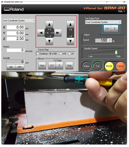
Step 5: Select "User Coordinate System" from the "Set Origin Point" by clicking on "XY" and "Z" in blue box . In the user coordinate system, this will make the current position the home or zero position.
Step 6: Move the milling bit a few millimeters above the PCB.
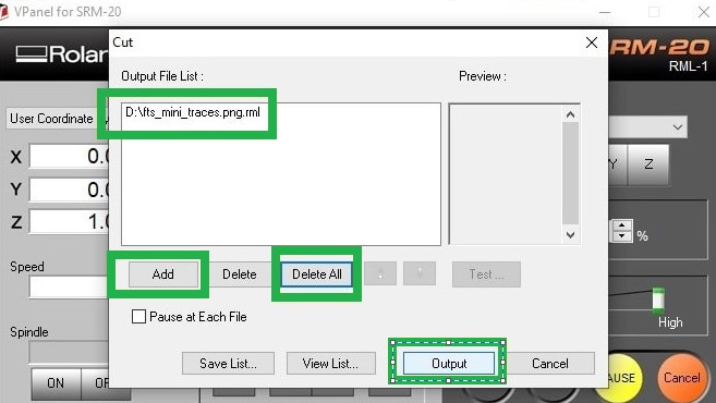
Step 7: Select "Cut" and then "Delete All" to get rid of any outdated jobs. Select the traces rml file by clicking "Add." finally Choose "Output" Now is the time for the machine to start.
Step 8: When the first job is finished, go to the "Move" menu and select "XY". The spindle will be moved to the "XY" home . lift up milling bit , cover it and remove it. after that install milling bit 1/32".
Step 9: Repeat steps 4 to 7 with "cut.png .rml" file, but don't change x , y coordinate for origin "home coordinate "
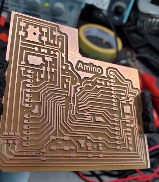
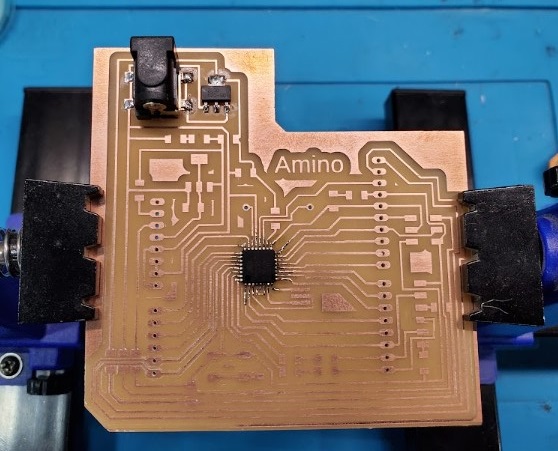
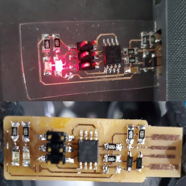
Rsults
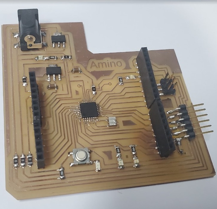
Soldering
Use the schematic as a reference for component values and placement while soldering the parts to the PCB.
Note the components that must be installed in the correct orientation:
-The LED cathodes on the PCB drawing are marked with dots and thicker lines. If you do not find the dots and thicker lines , determine the cathode using a multimeter.
-The ATMEGA328 marks pin 1 with a dot laser-etched into the corner of the package. Pin 1 is marked in the drawing with a dot as well.
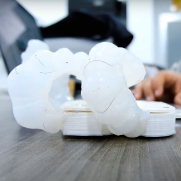
2.2. MYO (electromyography) and MyoWare sensor
The week's input device was a Myoware Muscle Sensor. I had to study the sensor's datasheet in order to understand how it worked. Electromyography is a technique for measuring muscle activity using electric potential (EMG). I could also move servo motors that controlled the fingers of my prosthetic arm using electromyography.
Three elecrodes on the myoware sensor should be attached to the muscle group selected. Two electrodes should be attached in the muscle's midsection, and the third electrode should be connected at the muscle's end. The reference electrode is the one that is linked to the muscle's end. I had to clean the region with Isopropyl Alcohol before applying the sensor to the muscle. The readings will be skewed or non-existent if the sensor is not set appropriately. As a result, the sensor's positioning on the muscle is critical.


After gaining a thorough grasp of the sensor's operation, it was time to wire it up and program it. The sensor's wiring was inspired by the example below.
Wire Connection
The sensor operates between 3 and 5 volts, so you'll need a GND and VCC connection. Connection of analog pins This sensor functions as an analog Pin PMW pin, which is similar to how a potentiometer works.

Programing
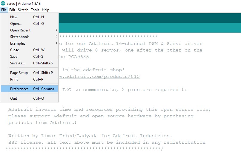
Although the microcontroller on this board is identical to that on the Arduino Uno, put the clock utilized is not, therefore we should use the Mini Core library to choose the clock for the atmega 328.
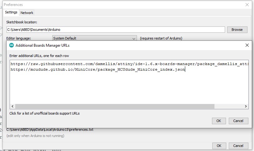
The first step will be to add the cards' download URL to the Arduino IDE. To do so, go to File > Preferences.
We will provide a button for managing additional URLs of cards in the new window that will open.
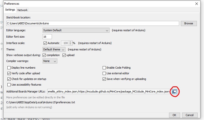
We'll paste the following link into the new window that pops up:
https://mcudude.github.io/MiniCore/package_MCUdude_MiniCore_index.json
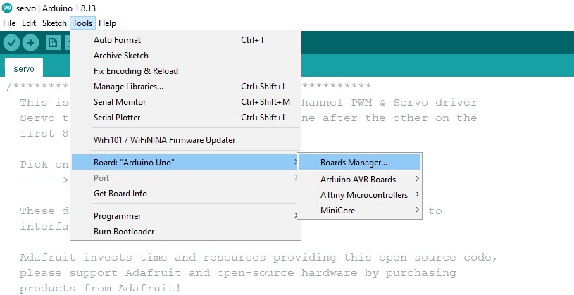
Finally, we give OK and close the two open windows. We'll proceed to install it once the foregoing is completed and the URL of the plates is entered. To do so, navigate to the Tools > Board > Boards manager and select the Boards manager.
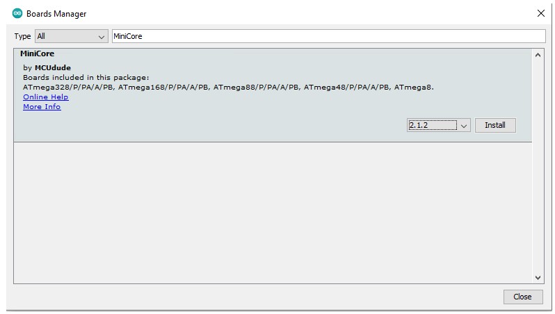
We'll seek for the MiniCore package there and install the most recent version.
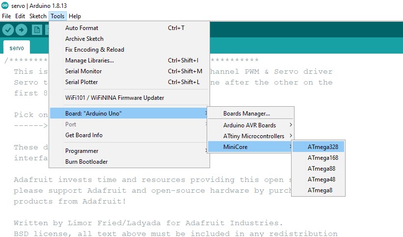
After installation, we can see that we have a number of additional boards to choose from, including the ATMega328p.
Choose clock speed.
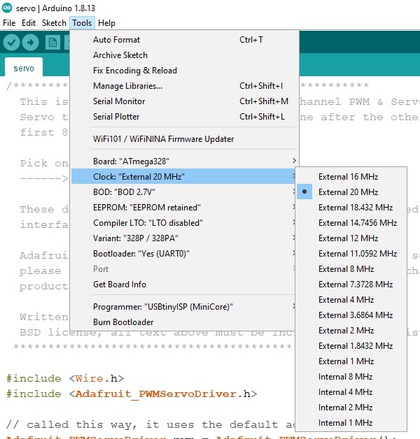
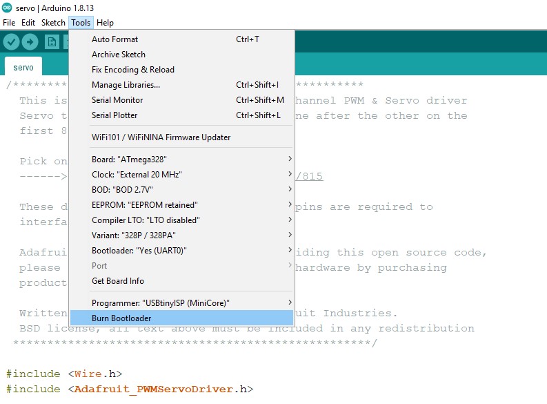
Now that we have everything installed and ready, we must burn the bootloader in order to change the ATMega328's clock speed. Connect the board and upload the ISP sketch to the Arduino we'll be using to burn it.
File to Download
Code
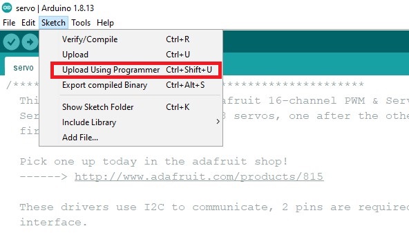
Finally, Click on sketch > Upload Using Programer
2.3. Hero Shot !


