Electronics design
1. Group assignment
use the test equipment in your lab to observe the operation of a microcontroller circuit board
VCC-GND
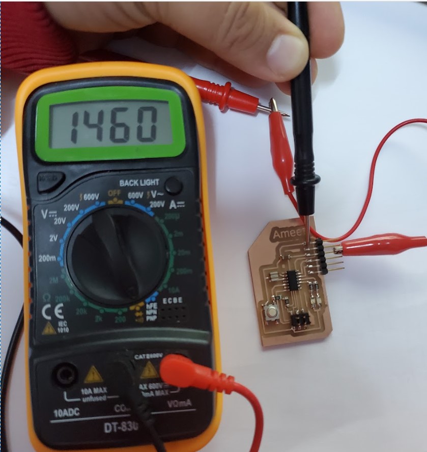
There should be no beeping from the digital multimeter when you connect between the VCC and GND pins. This indicates that the VCC and GND have no connection (short circuit).
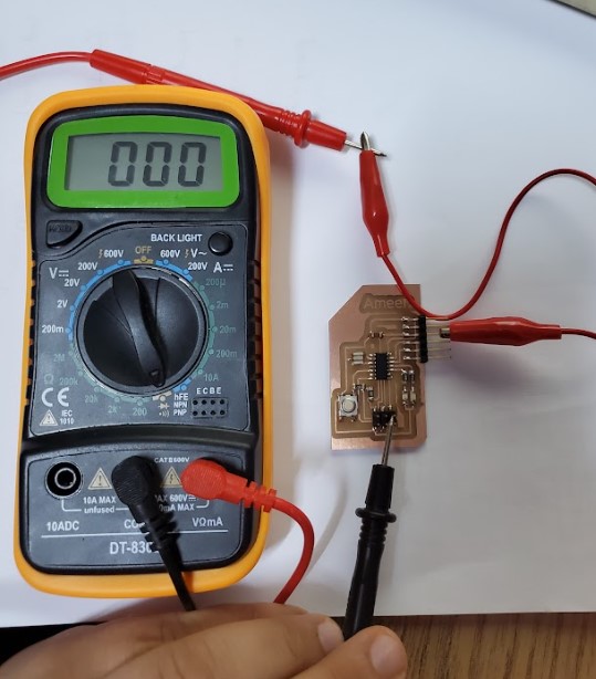
GND Continuity
The continuity between the ATtiny44's GND pins, the SPI header, and the FTDI header was tested. The digital multimeter should beep if it's working properly. This indicates that each of the three pins is connected.
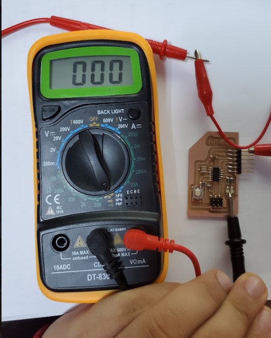
VCC Continuity
The continuity between the ATtiny44's VCC pins, the SPI header, and the FTDI header was tested. The digital multimeter should beep if it's working properly. This indicates that each of the three pins is connected.
2. Individual assignment
Redraw an echo hello-world board, add (at least) a button and LED (with current-limiting resistor) check the design rules, make it, and test that it can communicate extra credit: simulate its operation
2.1. Eagle software
In this section, I used Eagle to redraw the echo hello-world ATtiny44 board and added two LEDs and a push button.
EAGLE is electronic design automation (EDA) software that lets printed circuit board (PCB) designers seamlessly connect schematic diagrams, component placement, PCB routing, and comprehensive library content.
Download EAGLE
Download schematic diagram.brd
Download schematic diagram.sch
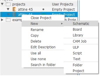
Step 1: Launch the Eagle program. The "Control Panel" is what it's called. Right-click on "Projects," then choose "New Project" and give it a name. This will be the location where the schematic and PCB will be stored.

Step 2: Select "New > Schematic" from the context menu when right-clicking on your project. This will create a schematic and launch the "Schematic Editor" for your project.
Step 3: Next, we'll install the Eagle fab library (fab.lbr). Unzip the file after downloading it in "..DocumentsEAGLElibraries".
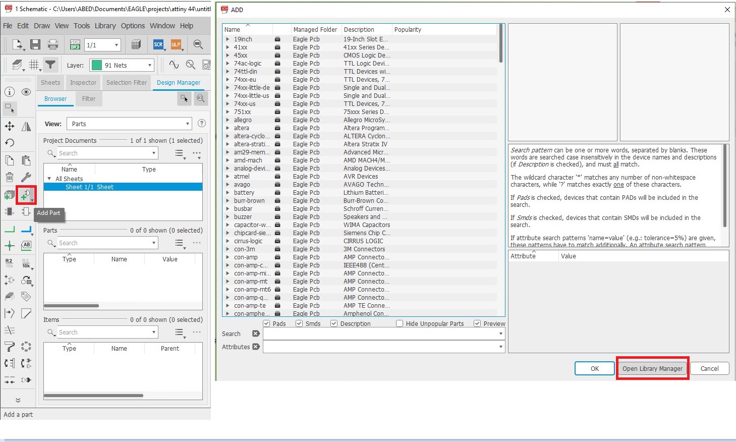
Go to "add part > Open library manager" in Schematic Editor
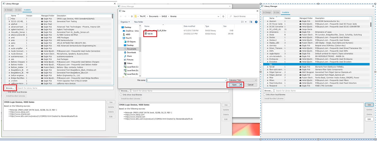
Step4: Go to the "Available" tab. Locate fab.lbr on your hard disk by clicking "Browse." Select "Open" from the menu. This adds fab.lbr to the list of "Available" libraries.Click "Use" after selecting fab.lbr from the list. This will add fab.lbr to the "In Use" list, allowing the schematic editor to access all of the components defined inside.
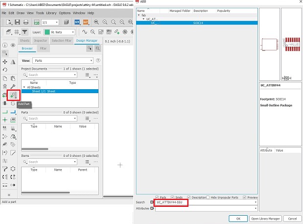
Step 5: First, we'll add the components from the original echo hello-world board to the schematic. Click "Add Part" and type "lib Name" into the search area. Under fab library, Click "OK" after selecting the result To place the part, click on the schematic editor work area. To alter the name and value of a component, use the "Name" and "Value" tools and click on the "+" mark on the component.
| Description | Reference | Lib Name | Quantity |
|---|---|---|---|
| ATtiny44 | IC1 | UC_ATTINY44-SSU | 1 |
| Crystal 20MHz | XTAL1 | XTAL_RESONATOR | 1 |
| Header 3x2 ISP | J1 | CONN_03X2_AVRISPSMD | 1 |
| Header 1x6 FTDI | J2 | CONN_06_FTDI-SMD-HEADER | 1 |
| Capacitor unpolarized 1uF | C1 | CAP_UNPOLARIZEDFAB | 1 |
| Resistor 10kOhm | R4 | R1206FAB | 1 |
Step 6: Add the components in the table below to the board . To add to the schematic, follow the same methods. Remember to keep a copy of your schematic.
| Description | Reference | Lib Name | Quantity |
|---|---|---|---|
| Resistor 10kOhm | R3 | R1206FAB | 1 |
| Resistor 499Ohm | R1, R2 | R1206FAB | 2 |
| Green LED | D1 | LEDFAB1206 | 1 |
| Red LED | D2 | LEDFAB1206 | 1 |
| Push button | S1 | SW_SWITCH_TACTILE_6MM6MM_SWITCH | 1 |
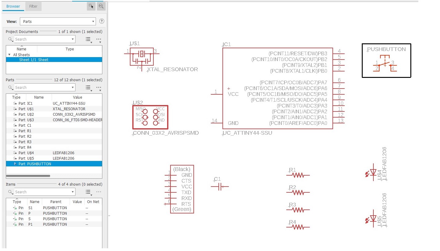
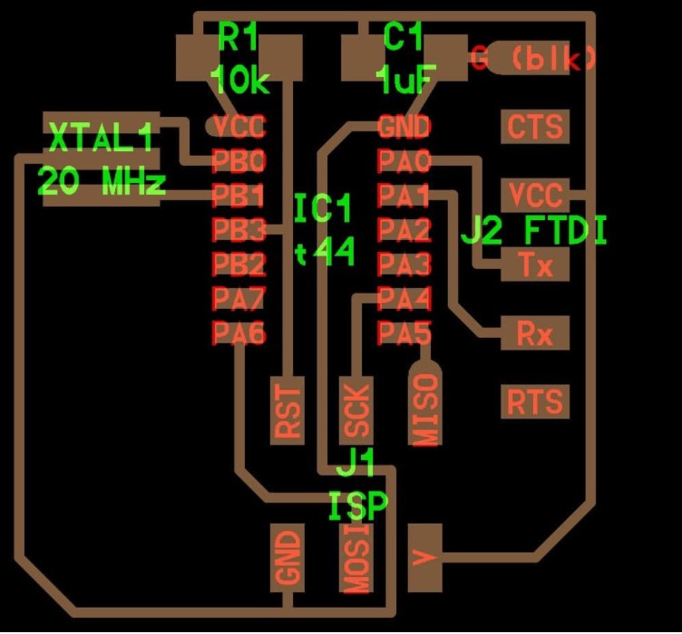
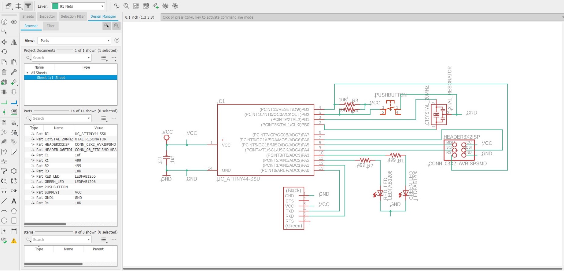
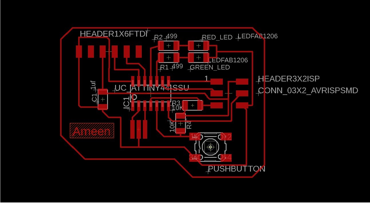
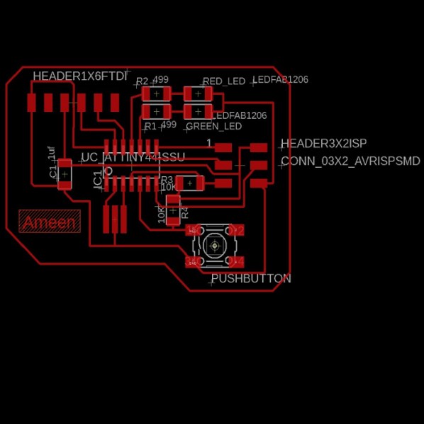
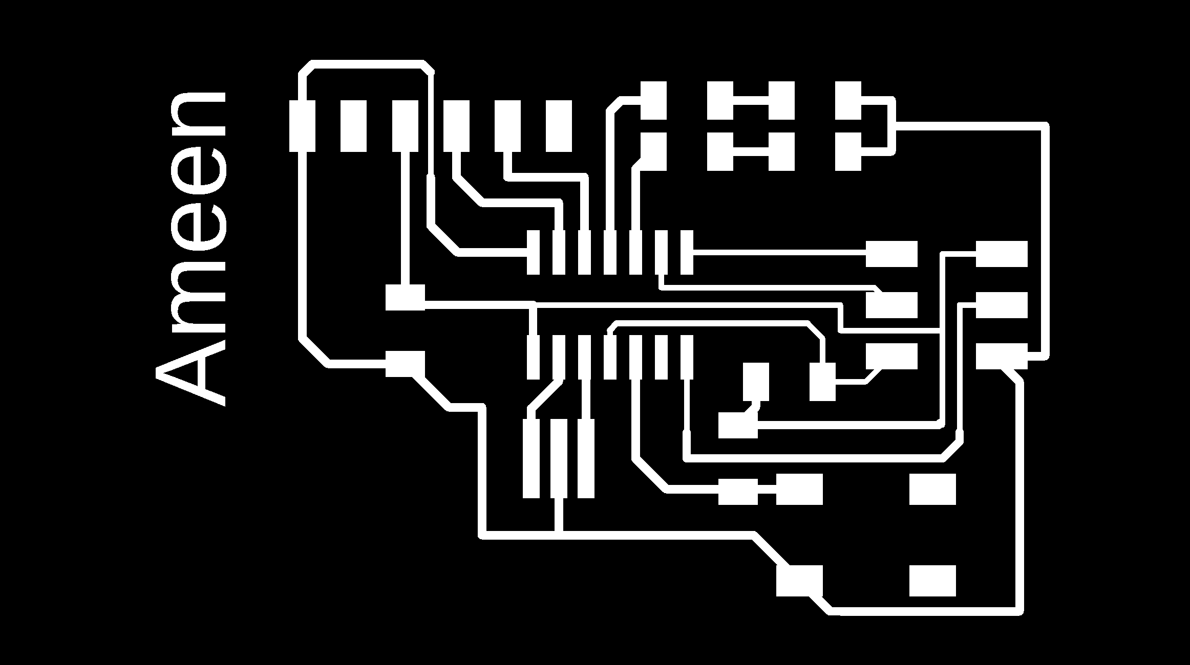
Your schematic should resemble the one shown below. You can arrange the components in the schematic in any way you choose.
Step 7: Using the "Net" tool, add wire to components as per the original echo hello-world ATtiny44 board. When possible, make direct connections between components. Add names to open connections using the "Name" tool.
Step 8: The schematic is now ready to be used to make the PCB. Go to "File > Switch to board" in "Schematic Editor." When the warning message "Create from schematic?" appears, select "Yes." The "Board Editor" window appears, and all components are inserted in the schematic editor using their footprints and connections.
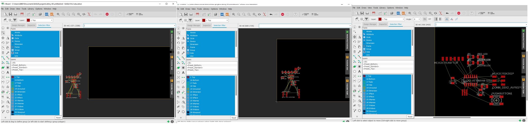
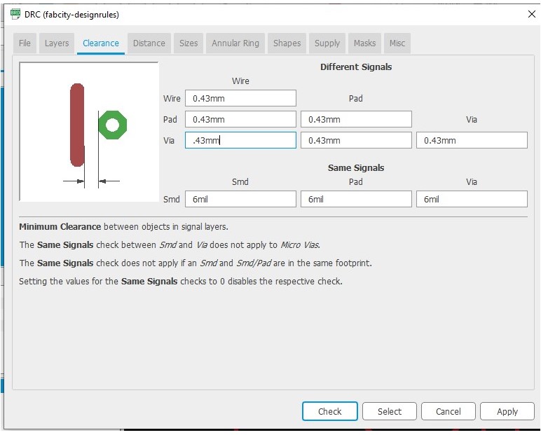
Step 9: The fine yellow wirings represent the schematic connections. The "Route Airwire" tool should be used to change all of those wirings. Before we get started, go the tool list click on CRV then choose clearance,To fit with a 1/64" milling bit,the minimum spacing between routes (0.41 mm) are required. so edit the to be as the figure below .
Step 10: Replace fine yellow connections between your components with the "Route Airwire" tool. Finding an appropriate location for components may take some tim, finally draw a cutting lines around the board.
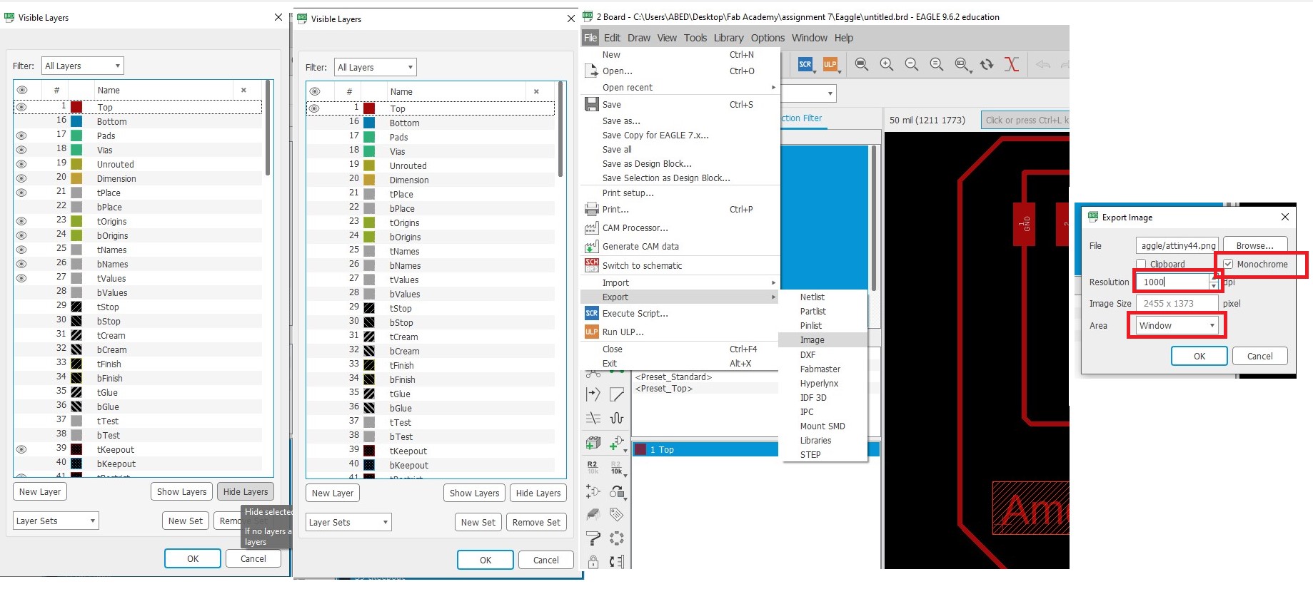
Step 11: Now we'll export the traces and interiors as png files, which we'll use to make rml files for the milling machine using mods. Select the eye icon in "Layer Settings" to hide all layers, leaving only "1 Top" visible. "OK" must be chosen.To fit your board within the window, zoom it in. Go to "File > Export > Image" in the menu bar. Give your file a name, select "Monochrome," set the resolution to "1000 dpi," and choose "Window" as the "Area." "OK" should be selected.
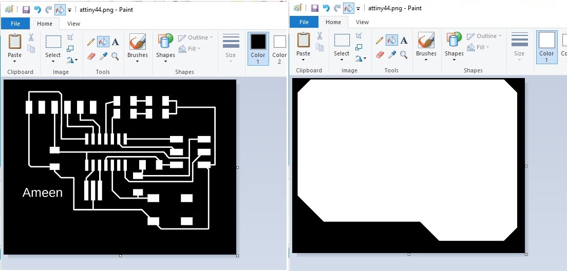
Step 12: To crop the exported image, I used paint. After cropping, I export two images one for tracing and one for cutting out line.
2.2. Modes
Download file
outline.png
outline.rml
trace.png
trace.rml
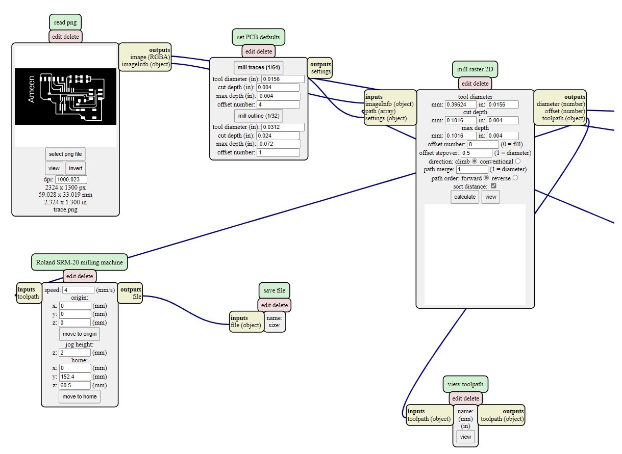
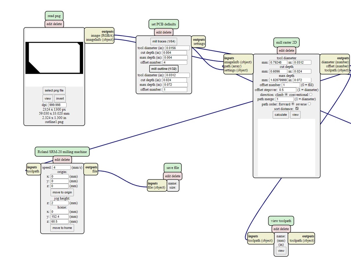
step 1: Open Mod and Right click any whare. select programs - open server program - PCB png from Roland SRM-20 list.
Step 2: On the “read png” block Click on select png file and choose the "trace.png"
Step3: Select mill trace from “set PCB defaults” block.
Step4: On the “Roland SRM-20 milling machine” block let the origin coordinates 0,0,0
Step8: Right click and select modules - open server module- save.
Step9:- replace "websocte device" block with "save file" block .
Step10:- Click on calculate in "mill raster 2D" block , The RML file will be downloaded automatically.
Note : you can have better finish if you make the offset more than 4 like 6 but it will take more time.
Step11:Repeat the previous steps on the outline.png file, but click on the mill outline rather than mill traces from set PCB defaults block , to have outline.rml file
Note: check the job dimention before calculate.
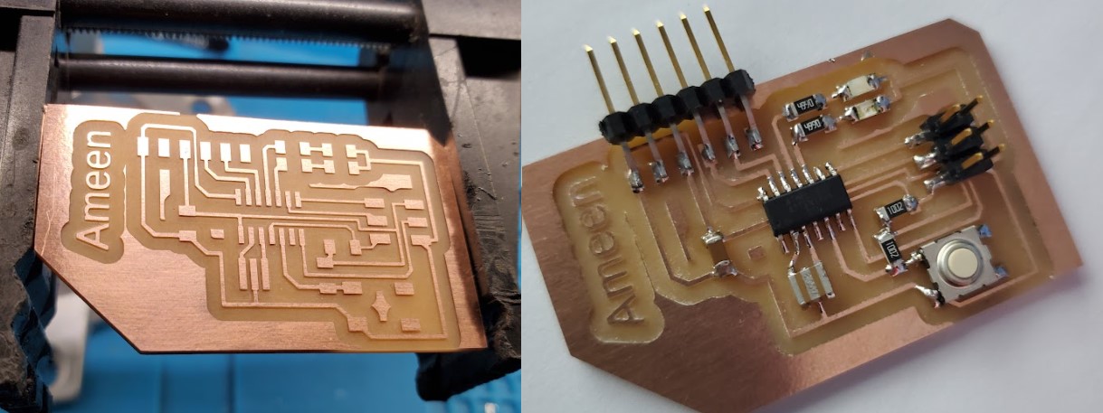
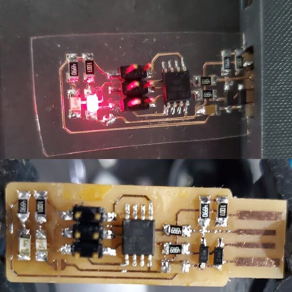
2.3. Milling & Soldering
Use the schematic as a reference for component values and placement while soldering the parts to the PCB.
Note the components that must be installed in the correct orientation:
-The LED cathodes on the PCB drawing are marked with dots and thicker lines. If you do not find the dots and thicker lines , determine the cathode using a multimeter.
-The ATtiny45 marks pin 1 with a dot laser-etched into the corner of the package. Pin 1 is marked in the drawing with a dot as well.
2.4. Programming
Download File
Download hello.ftdi.44.echo.c
Download makefile
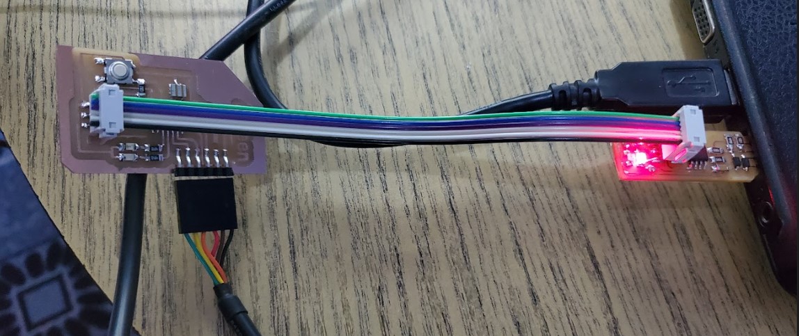
Step 1: Get the C and Makefile files. Save the makefile to your computer and rename it to "Makefile." Using the SPI cable, connect the board to the FabTiny programmer. Through the FTDI header, connect the FTDI cable to the board. Assemble the cables in the correct order so that the board, SPI cable, and FTDI cable all have the same GND. the programmer and the FTDI cable should be connect to USB ports .
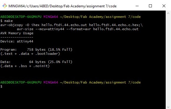
Step 2: In the folder where you saved the C and makefile, run "Git Bash." Execute "Make" in the git bash window to generate the HEX file that will be uploaded to the board.
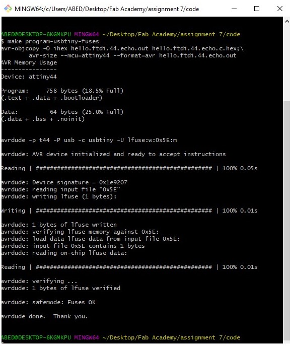
Step 3: Type "make program-usbtiny-fuses" in the git bash window. The ATtiny44 fuses will be programmed as a result of this.
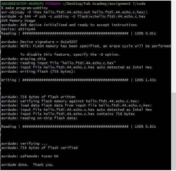
Step 4: Type "make program-usbtiny" in the git bash window. The HEX will be uploaded to ATtiny44 as a result of this.
Step 5: To test the software, I used "Arduino Serial Monitor." Set the baud rate to "115200," then type a character and click "Send." The board should echo your input and print a customized message in response. Character by character input is recommended.


