Computer-controlled cutting
1. Group Assignment
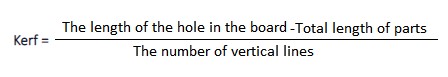
The assignment is to calculate the kerf and characterize your lasercutter’s focus, power, speed, rate, kerf, joint clearance and types
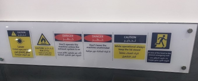
When dealing with laser machines, safety precautions and procedures must be taken into account. All caution signals should be read, understood, and followed.
When the machine is turned on, the bed will slide down and the laser head will move to the left to serve as a reference. When the reference is finished.
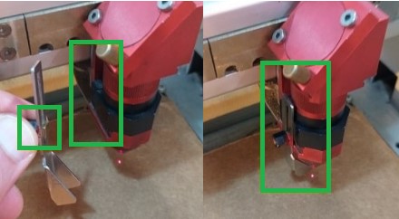
Focus on Working Piece :
Each time you place a fresh working piece on the machine bed, you should complete this step. Lower the bed if necessary by using the "AF DOWN" arrow, and move the Laser head to the desired location by pressing the up, down, left, and right arrow keys. Place the working component on the bed and the "Focus Tool" at the Laser head's preset location. Raise the bed by stages with the "AF UP" arrow until the focus tool contacts the functioning item on the bed and slips out of place.
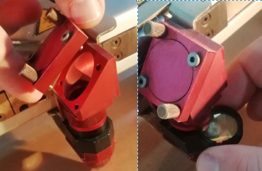
Checking Head Mirror and Lens :
The head mirror and lens should be cleaned and inspected on a regular basis. Remove the mirror by unscrewing the top of the head (two screws). Remove the lens by unscrewing the head lens holder. Any residuals should be checked in both places. Clean with the special cleaning wipes if necessary, and avoid contacting with your fingers. Return the head mirror and lens to their original positions.
Preparing
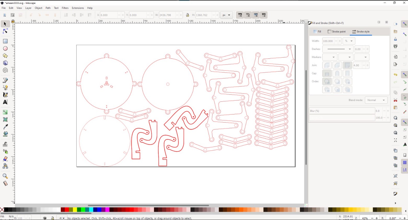
You can use Fusion 360, SolidWorks, Rihno, or any other program to create your 2D drawing and save it in dxf format. Then import your file into Inkscape, where you may use the print menu to send your job to the machine.
Note You can transmit your task to the machine using Rihno or Illustrator the most crucial think its to follow the color code because the Laser machine recognizes cutting settings by colors.
1.1 Customize power and speed
Step 1:Download files
Download Relief.svg
Download standard.svg
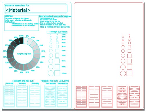
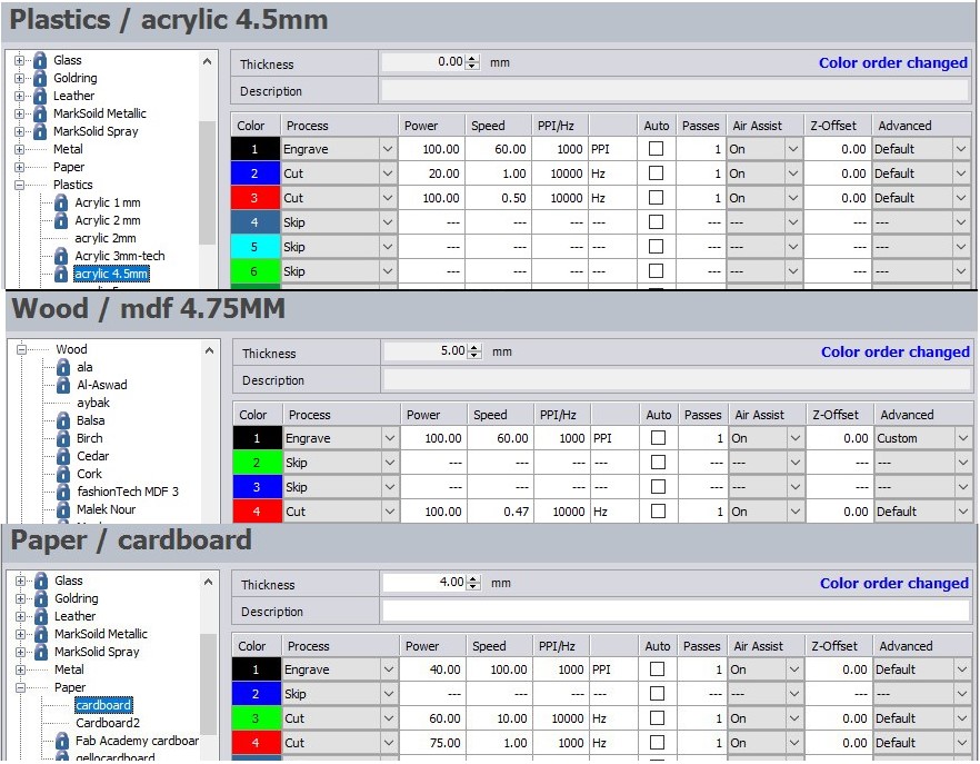
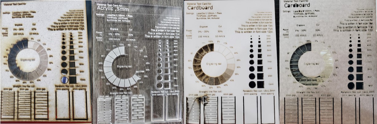
Step 2: Type the name of the material, This test will be divided into two parts. The first part is to engrave with various powers"Relief", and the second task is to cut"standard".
Step 3: press "control+p" in each file and click on preferences.

Step 4: For engraving job you must select relief as Process mode and for cutting job you must select standard as Process mode.
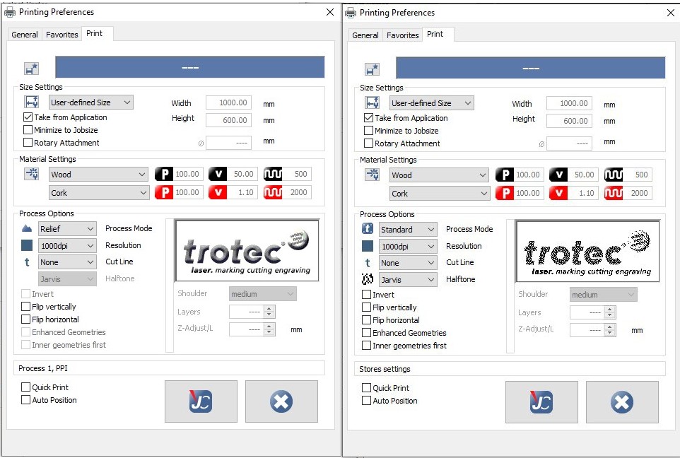
Step 5: Go to the laser software and select the settings as you shown below then Adjust the focus in the mid of the board after that Move the laser head to the corner of the board and place the job on it
after that run the jobs.
Not: don't forget to add mark at the first job corner to align the two jobs.
The Result
Warning: Before opening the cover of laser machine, make sure that all gases are out.
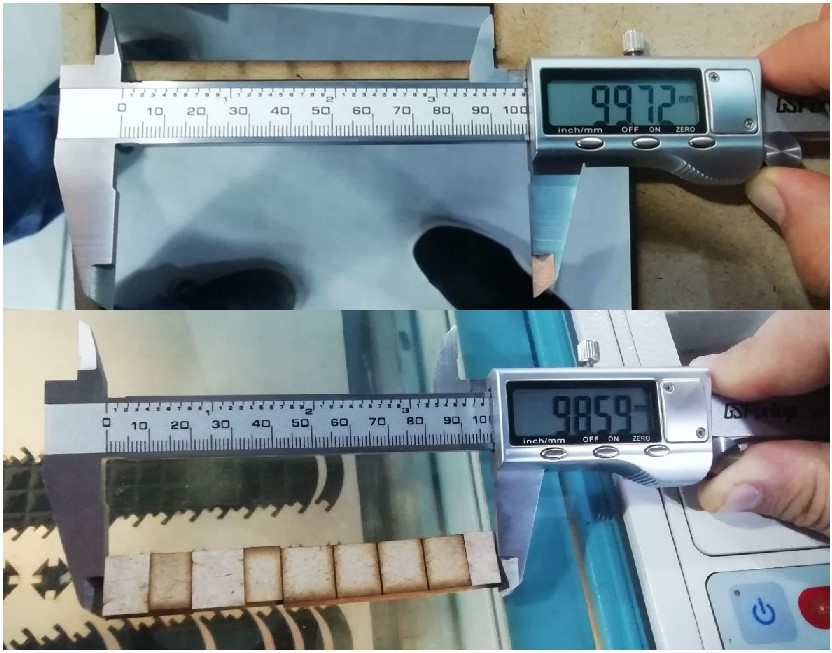
1.2 Kerf
To compute the kerf, I used InkScape to draw a rectangle and then divided it into 9 rectangles, as seen below.

2. Individual Assiignment
Design, lasercut, and document a parametric press-fit construction kit, which can be assembled in multiple ways. Account for the lasercutter kerf.
cut something on the vinylcutter
2.1 laser cutter
Machine: Trotec speedy 400
Safety: When dealing with laser machines, safety precautions and procedures must be taken into account. All caution signals should be read, understood, and followed.
2.1.1 Design
Two designs were made, the first design is a parametric design for the construction kit and the second design is a folding table that contains many applications that we use on the laser machine like leaving heung, mechanical mechanism, joint and Damascene mosaic.
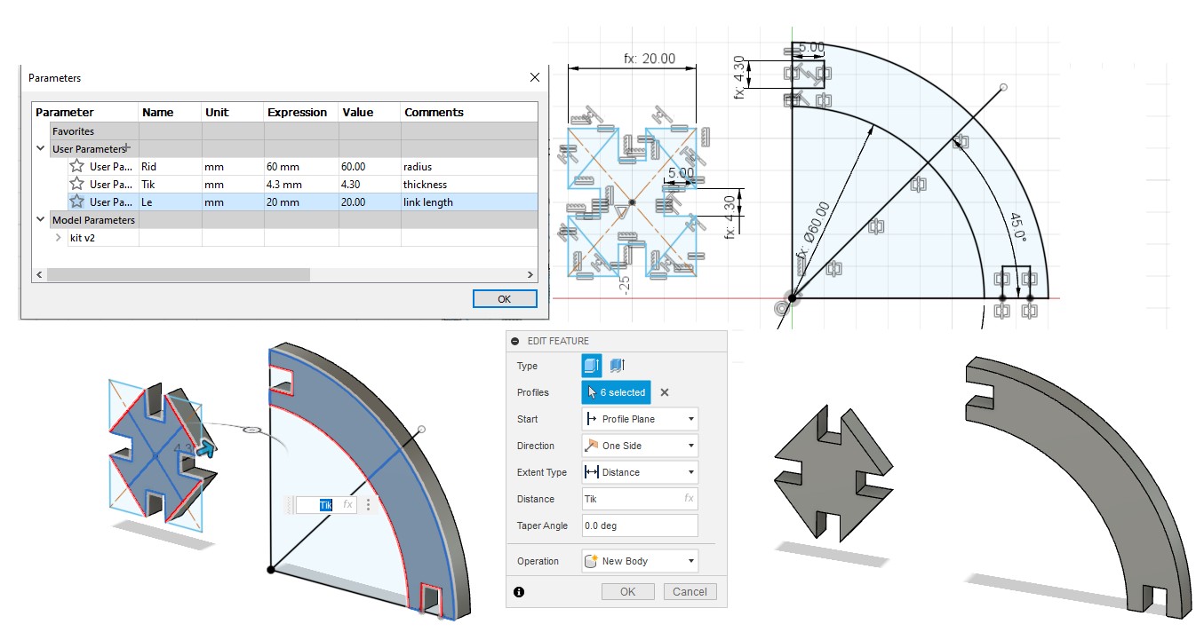
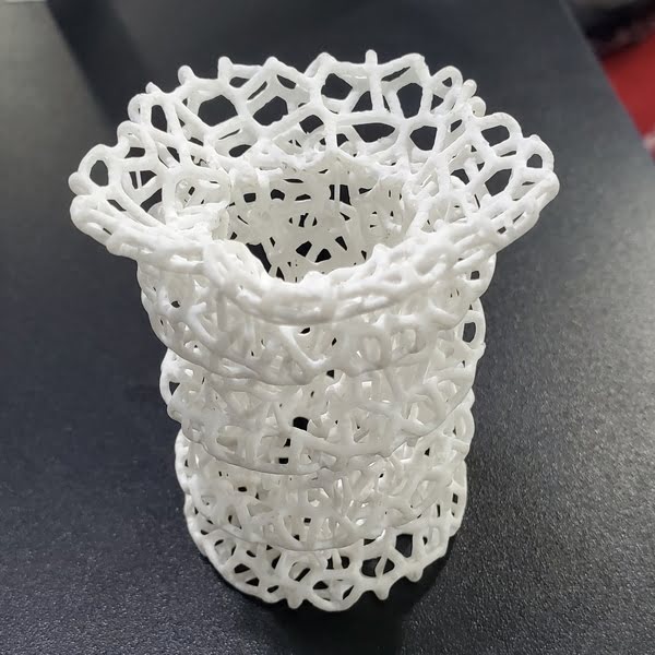
2.1.1.1 Construction Kit
I focused on creating a construction kit for making flexible open bodies for this project. I used Fusion 360. Each block has a parametric design.
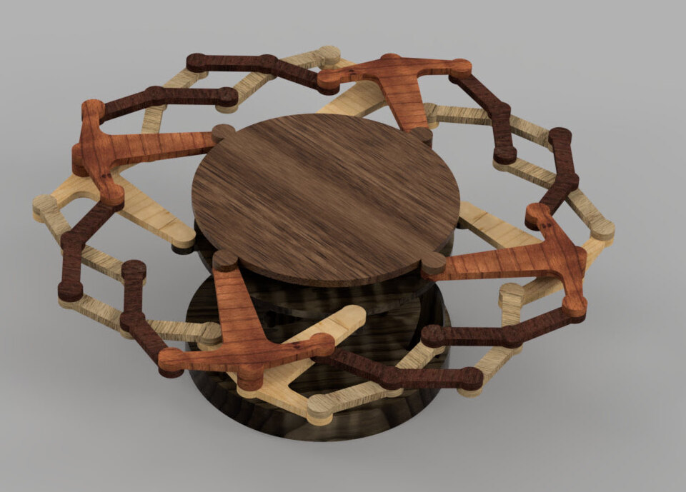
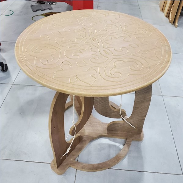
2.1.1.2 Design Foldable Table
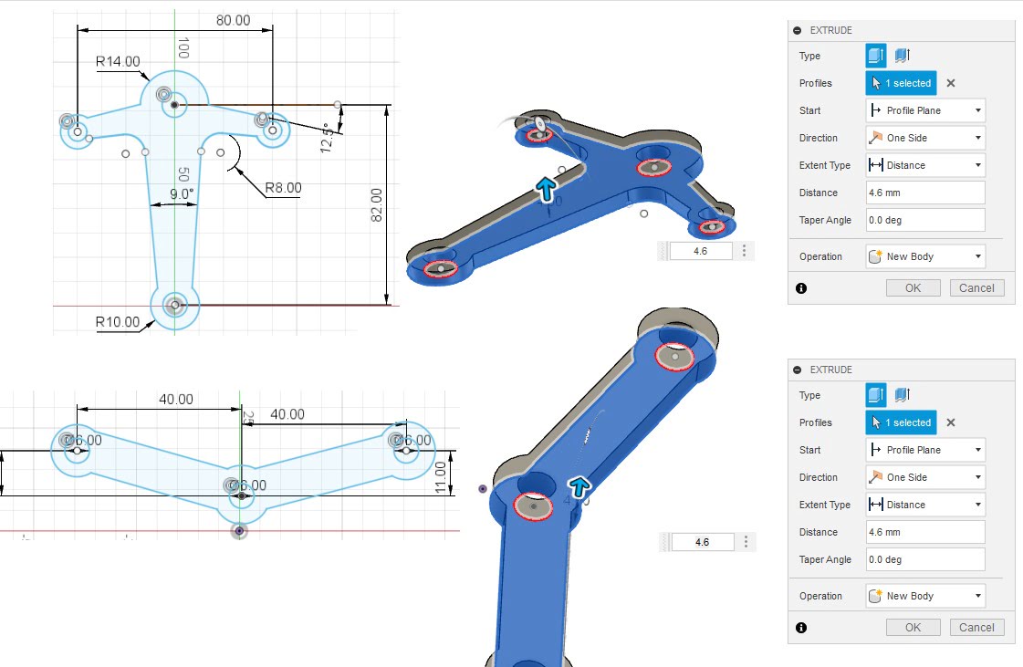
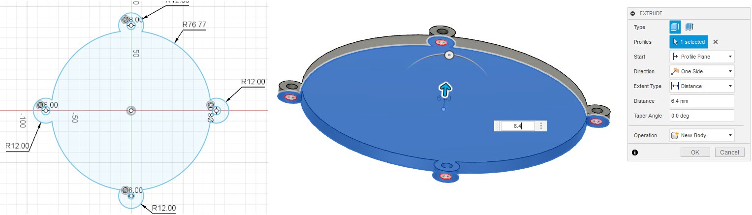
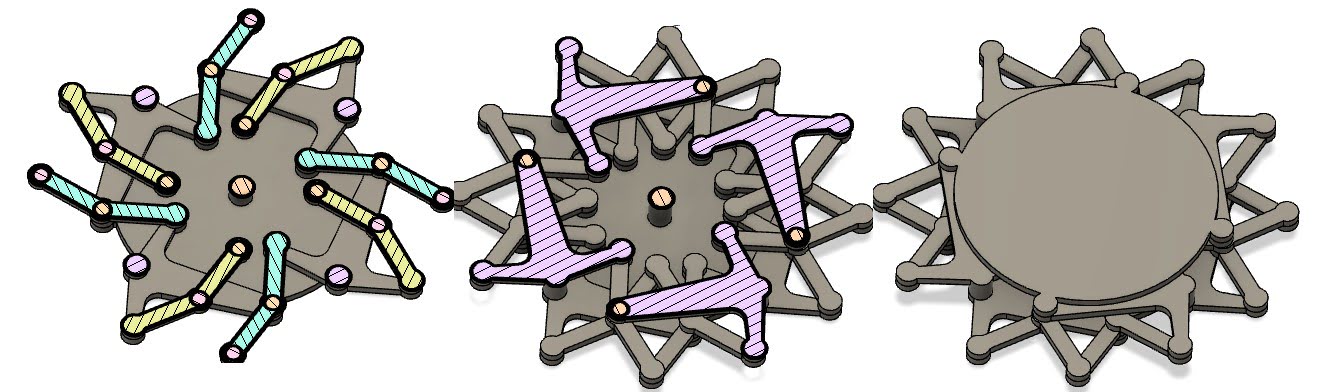
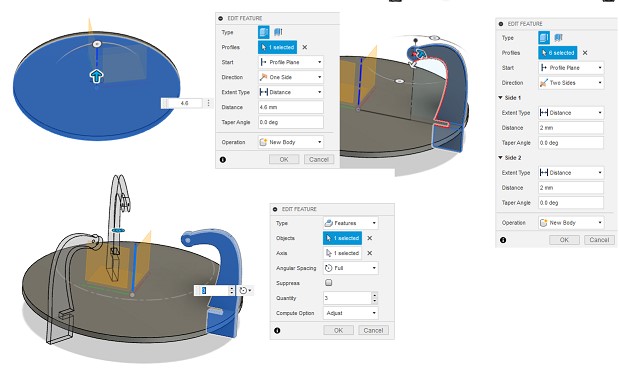
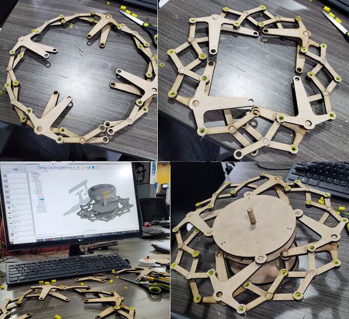
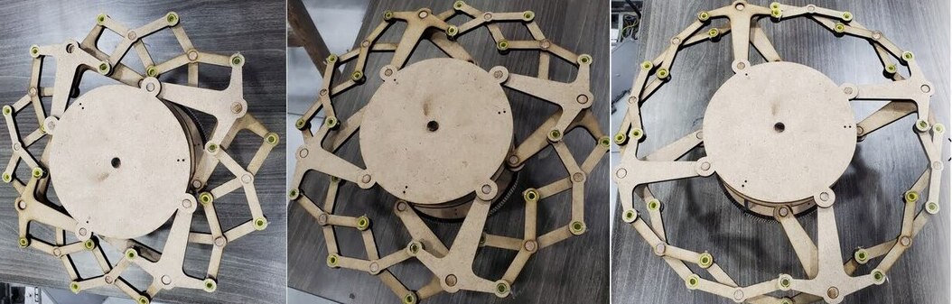
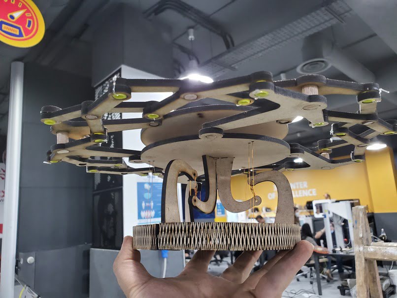
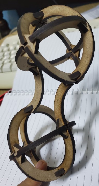
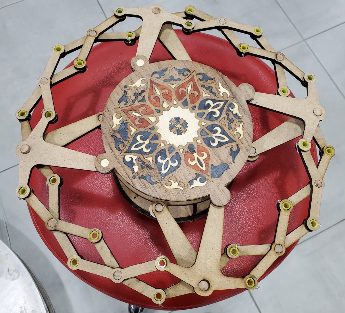
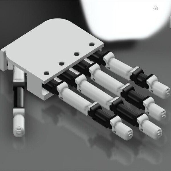
In this design, I wanted to show as much of the capacity of the laser cutting machine as possible, so I worked on a modern design that includes a mechanical mechanism, a suspension system, a Damascene mosaic and a living hinge. The mechanical mechanism consists of three repeated pieces, as you can see below
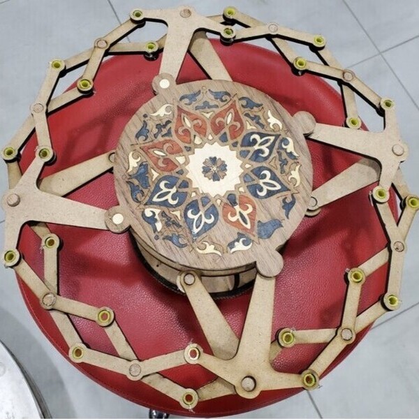
The suspension system depends on attaching the top and the base with ropes, this will help absorb vibrations and add aesthetics to the design
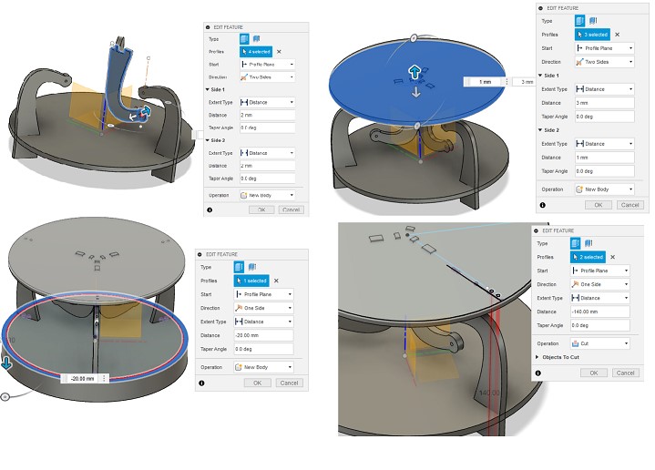
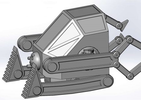
This is a 3D model showing the final design.
2.1.2 laser cutting
Download the files
Download Design Foldable Table.svg
Download th3 3d Design for Foldable Table
Step 1: Select all parts and press "control+shift+r" to (resize page to selection) then press "control+p" to go to the printer's software
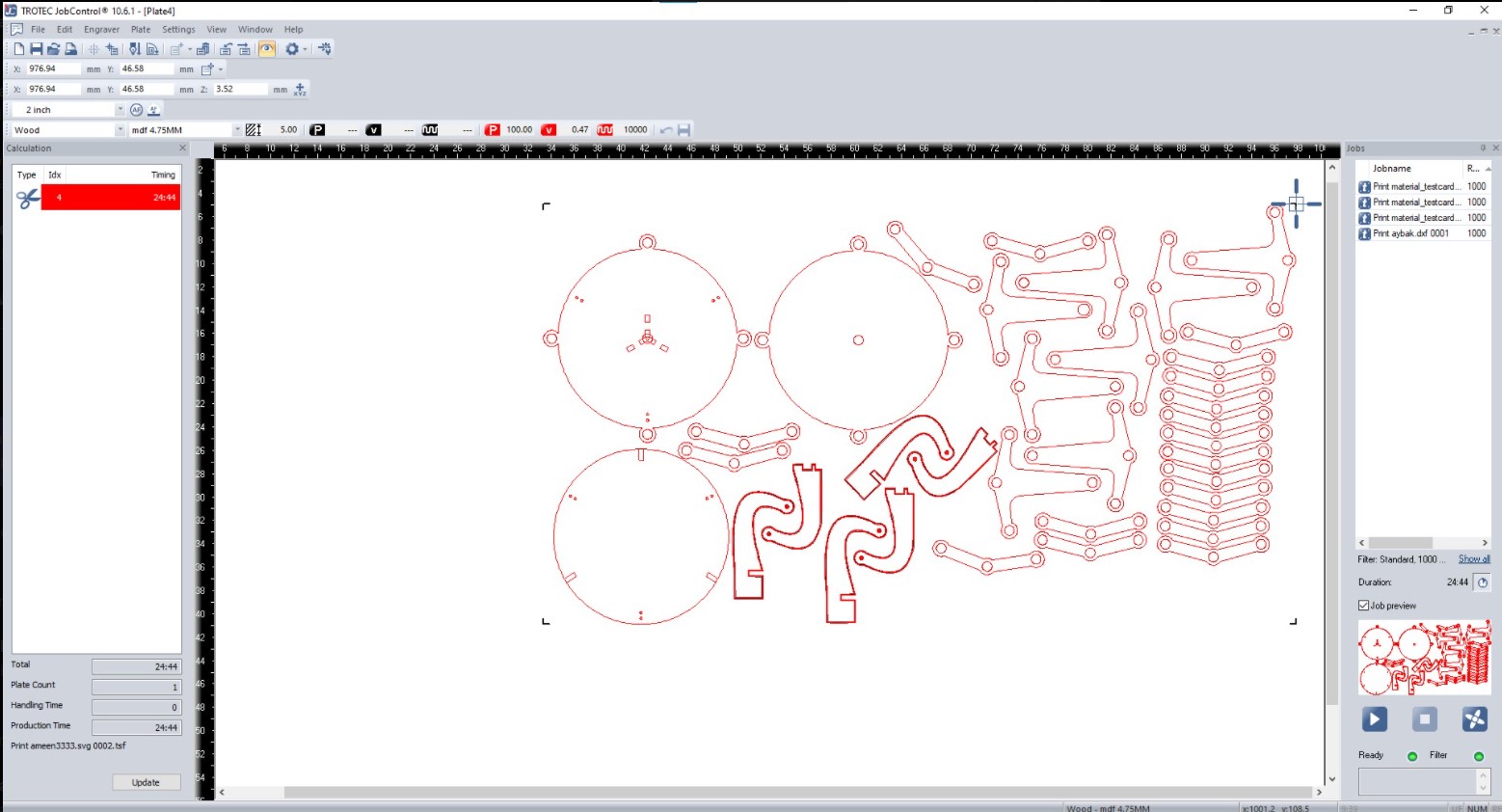
Step 2: Adjust the focus in the mid of the board after that Move the laser head to the corner of the board and place the job on it when you finish Choose the type and thicknes of the material.
Warning: Before opening the cover of laser machine, make sure that all gases are out.
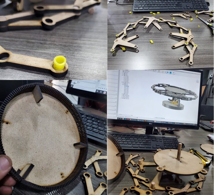
Step 3 : assembly all pieces regarding to the 3d cad model and pictures below.
Step 4: is to make the face of the mosaic. You need more than one type of wood paper. Cut the wood paper using a laser machine according to the shape into small pieces. Put a piece of wood or cotton under it so that it does not fall into the holes in the bed. Prepare a piece of wood according to the size and put a paper tape on it so that the small pieces do not fly out. use tweezers to arranging the final shape by mixing pieces of each type.
Note: The settings for cutting wood paper depend greatly on the type of wood and the method of manufacture, so it is recommended to try on small pieces before starting to cut the shape. You can start with paper cut settings.
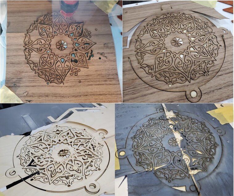
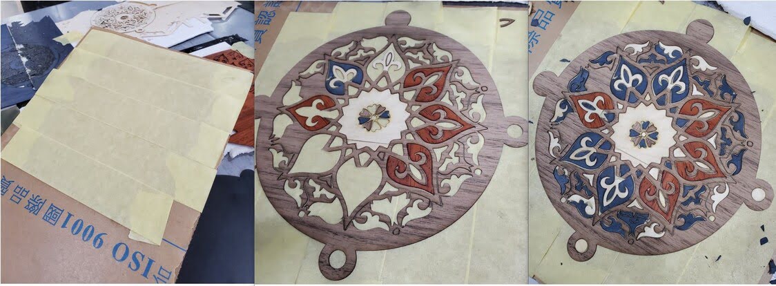
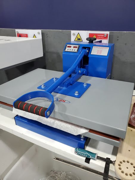
Step 5: When you have finished assembling the final shape, put a thin layer of glue on it “be careful not to fly the pieces” and then put it in the press without heat “according to the type of glue” for 24 hours.
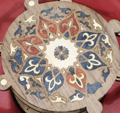
The result
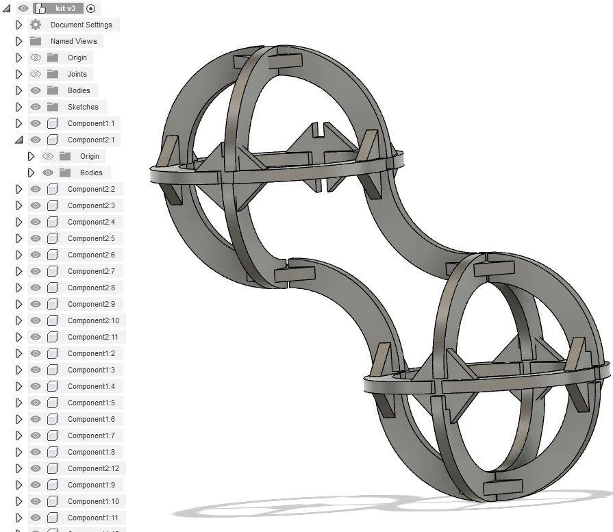
Assembly of Construction Kit
2.2 Vinyl Cutter
Machine: Roland CAMM-1 GS-24
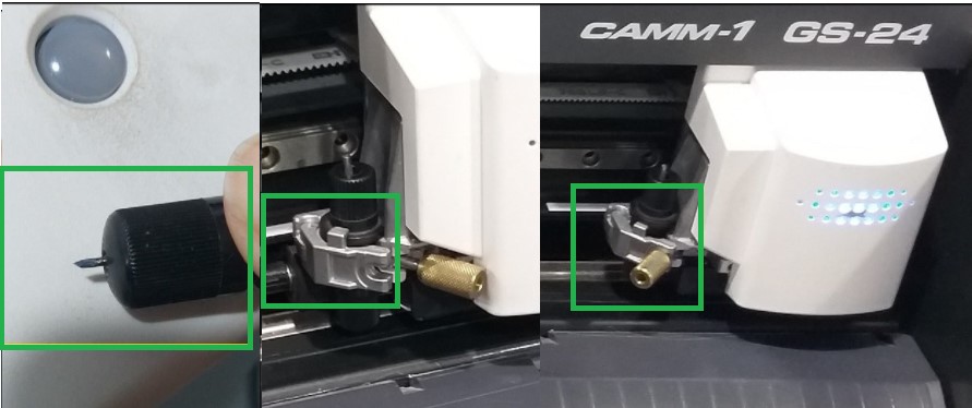
Cutting blade: For a good cut, the cutting blade should be sharp. To examine the blade condition, press the blade from the back end of the blade holder.
We rotated the blade holding cap and tested the blade tip on vinyl manual to calibrate the blade.
After that, the blade holder is inserted into the blade carriage. As indicated in the most right image below, make sure the circular edge in the blade holder is in the appropriate place and is held in place by the metal component. The blade is incorrectly placed in the center photograph. To keep the blade holder in place, tighten the holder screw.
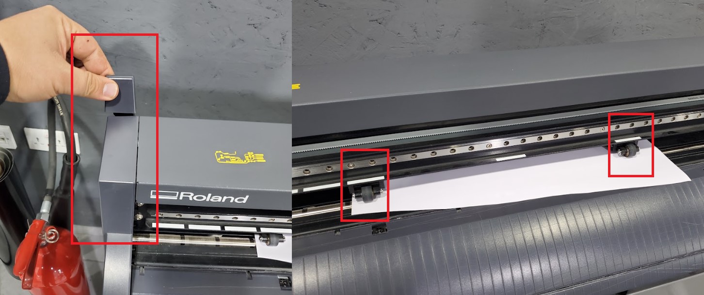
Placing the Vinyl Roll: The vinyl roll is positioned on the machine's backside bars. The vinyl was manually inserted under the machine rollers. Make sure the holding lever or handle is open so the vinyl can be inserted. Rollers should be moved in front of white bars on the machine to specify the cutting width. Between the two rollers will be the working width. To keep the roll in place, move the holding lever or handle to the closed position.
2.2.1 Design
Download files
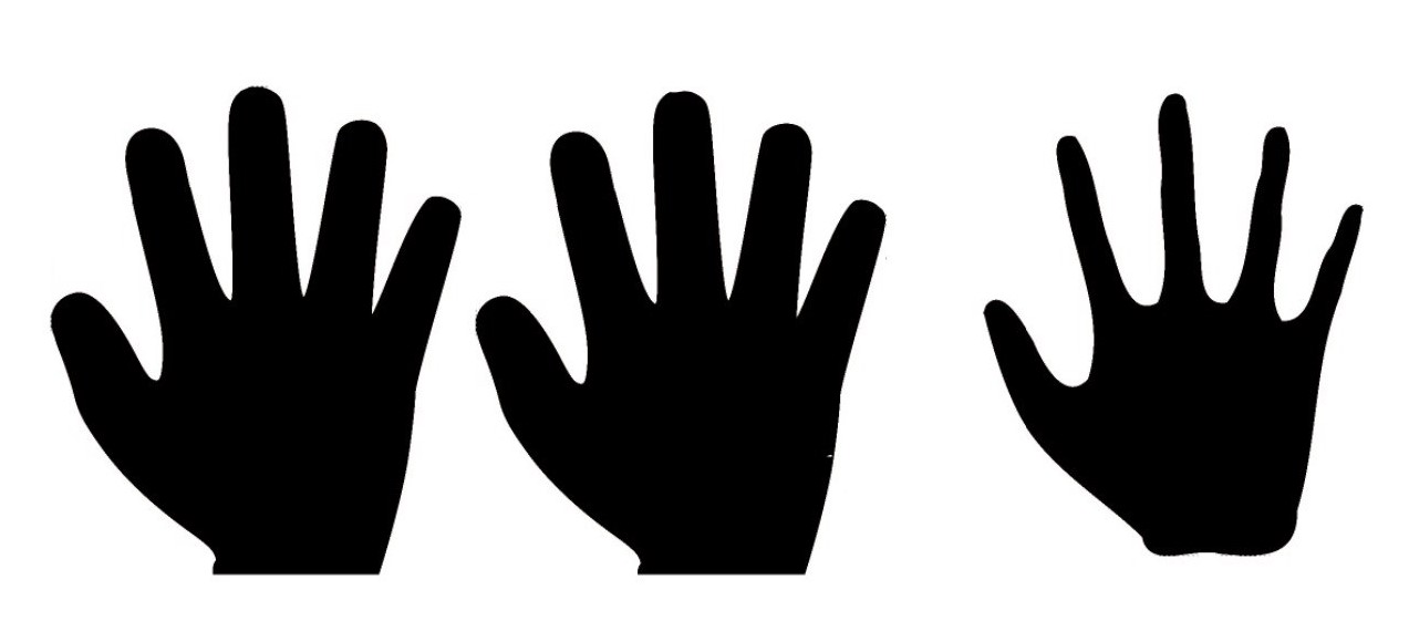
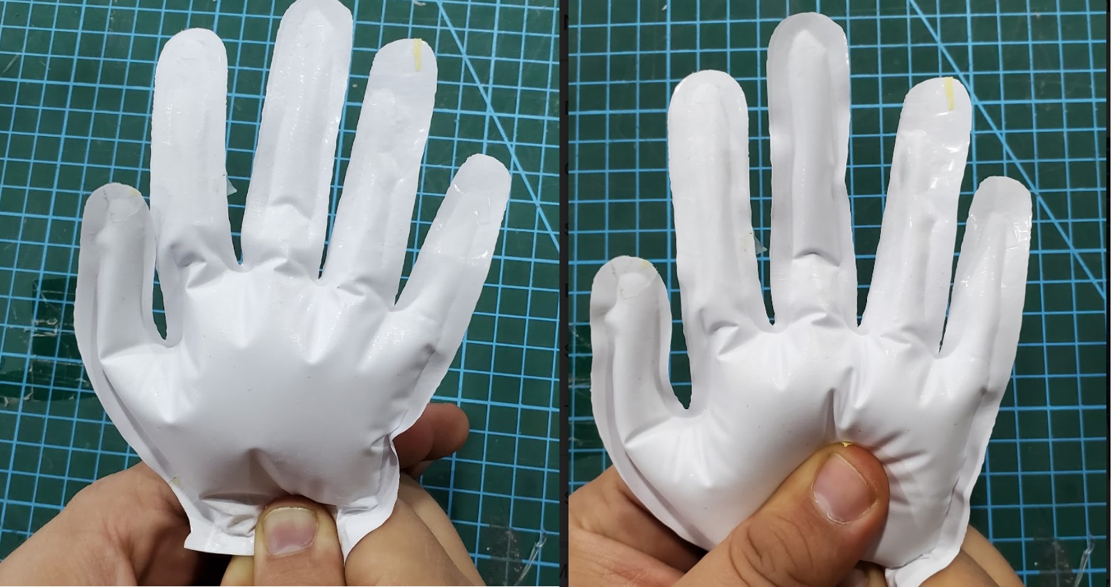
Balloon in the shape of a hand.jpg
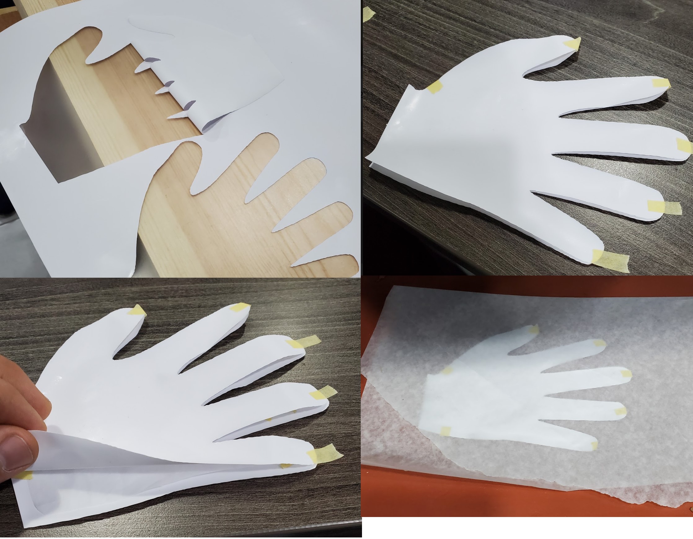
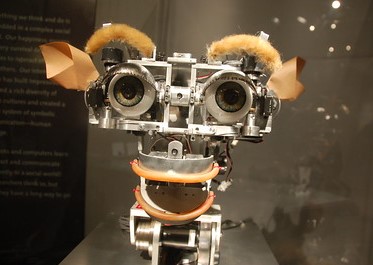
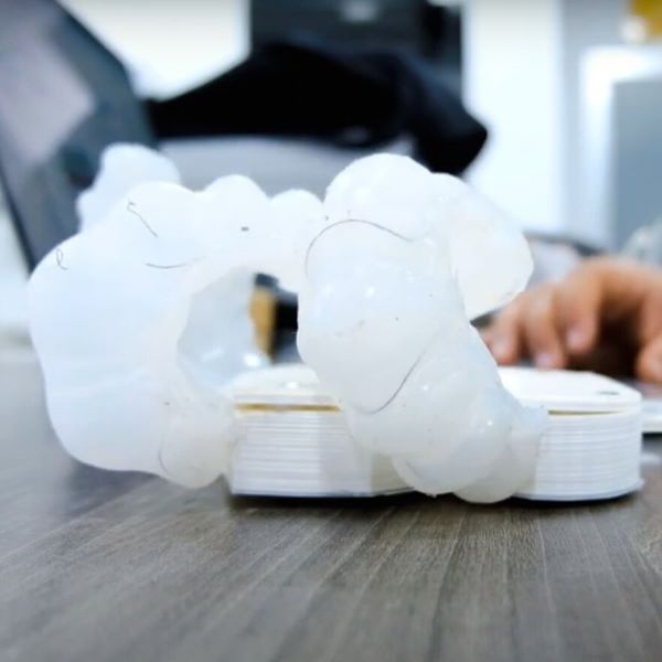
For a short time, I was interested in soft robots, so I decided to make a balloon in the shape of a hand, .
1- Insert the image to cut studio.
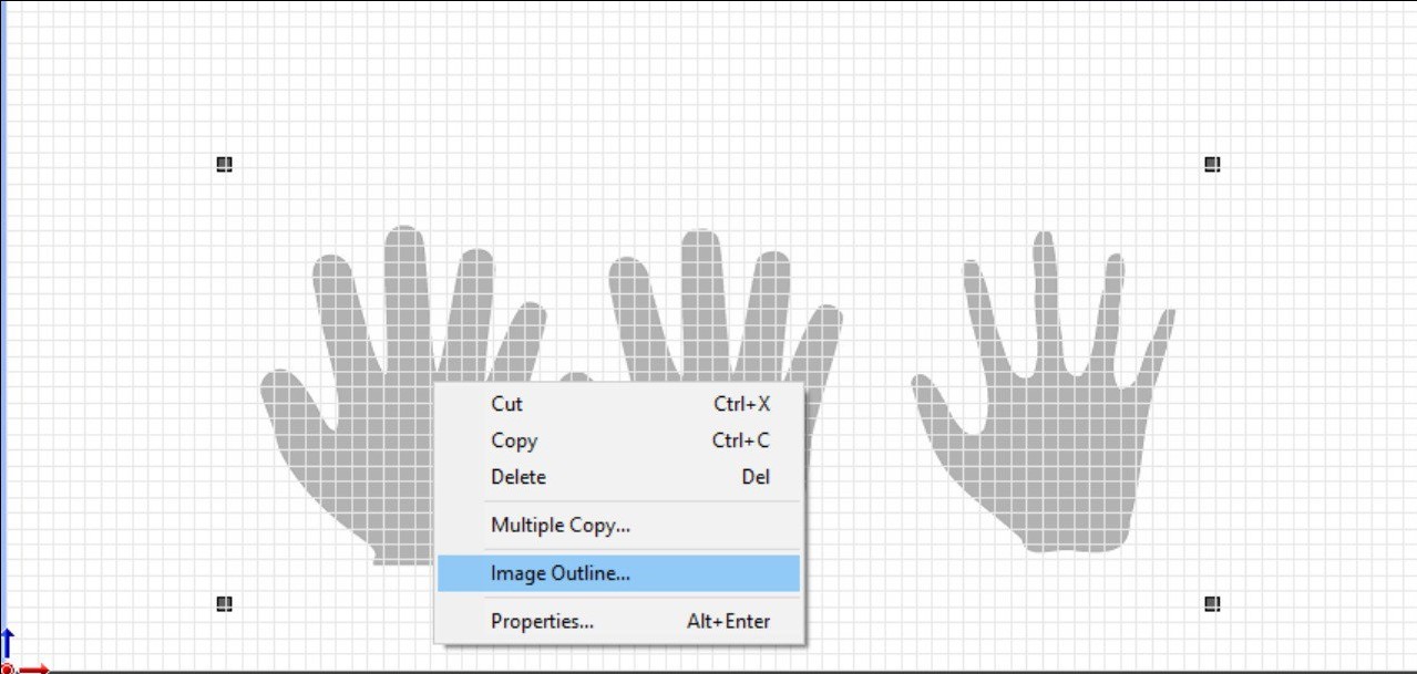
2-Right click on the image and select Image outline.
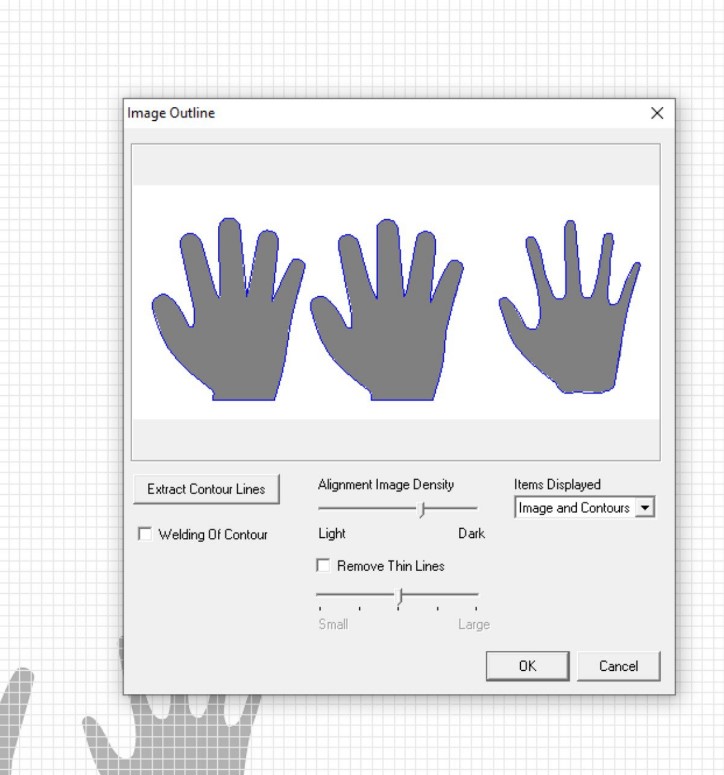
3-Click on extract contour line.
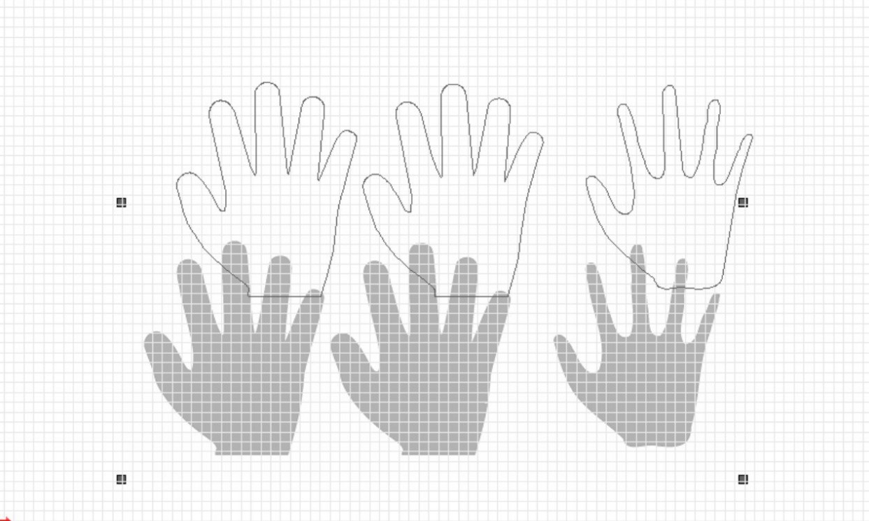
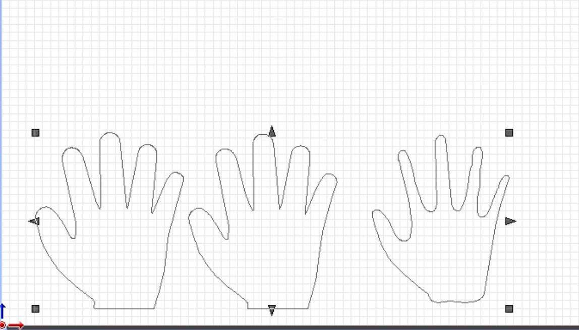
4-Delete the image and move the outline to origin.
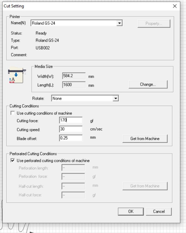
6- From file list select cutting setup. Change the speed and force to 5 and 40 then click ok.
8- Select the two part in the left and press "control+p" then change the material and cut the last part.
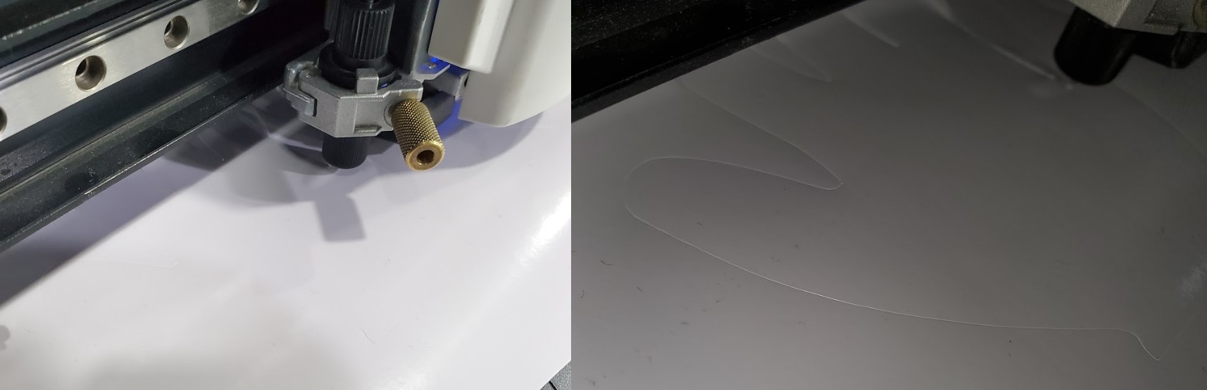
2.2.2 Vinyl cutting
You should make the first, second drawing in thermal vinyl and the third on paper. After cuting Put the parts on top of each other and align them, maket the paper in the middle, Make a place to inflate, Put them under the heat press for 30 seconds at 60C degrees.
3. Hero Shoot !


