3D scanning and printing
1.Group Assignment
-Test the design rules for your 3D printer(s)
-Document your work and explain what are the limits of your printer(s) (in a group or individually)
-Document your work to the group work page and reflect on your individual page what you learned
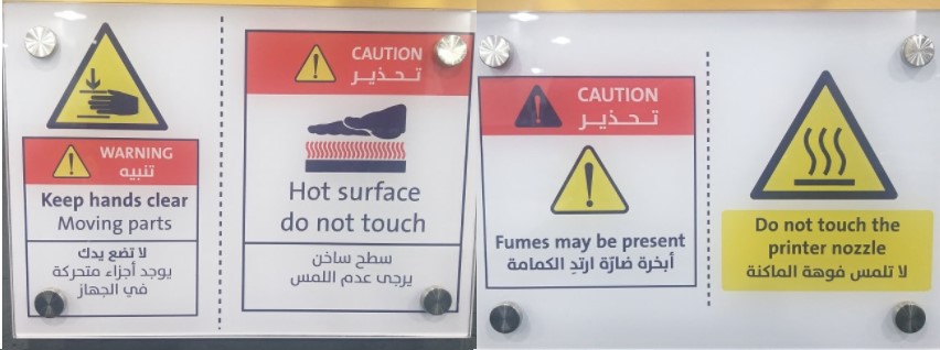
1.1. Safety First!
When dealing with 3D printers, safety precautions and procedures must be taken into account. All caution signals should be read, understood, and followed.
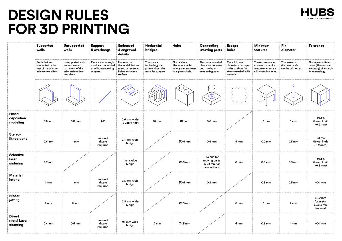
1.2. Design Rules
When working on a model for 3D printing, there are specific guidelines that should be followed. To get the best printing. Rules should be considered when creating the 3D model.
1.3. Clearance in different direction "FDM"
The air gap or clearance between the shaft and the holes is known as clearance fit. These clearance fits result in sloppy joints.
1.3.1. Download file
1.3.2. Design
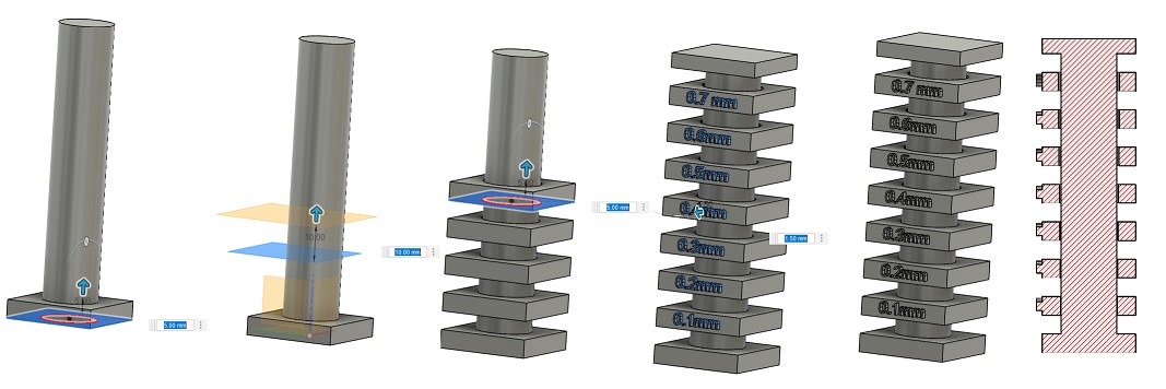
Shaft and rings were drawn around it with different gap to find the least clearance between the shaft and the ring allowing it to move freely
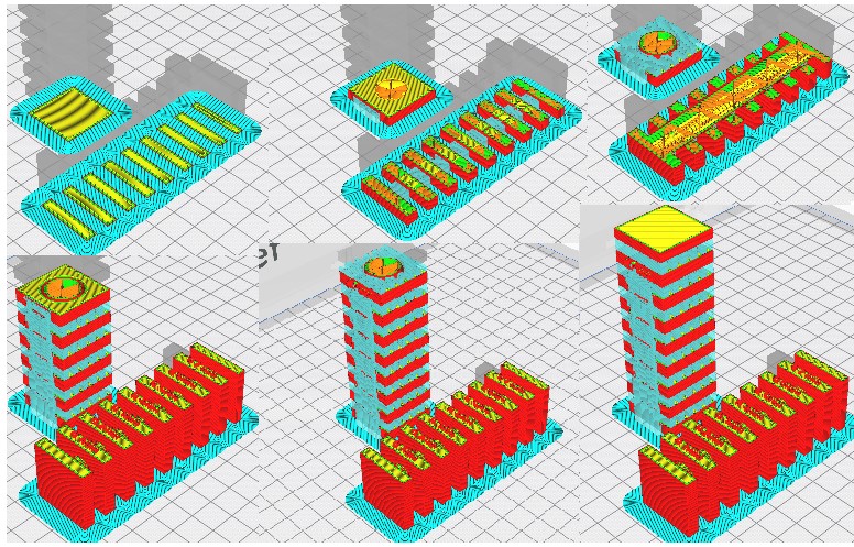
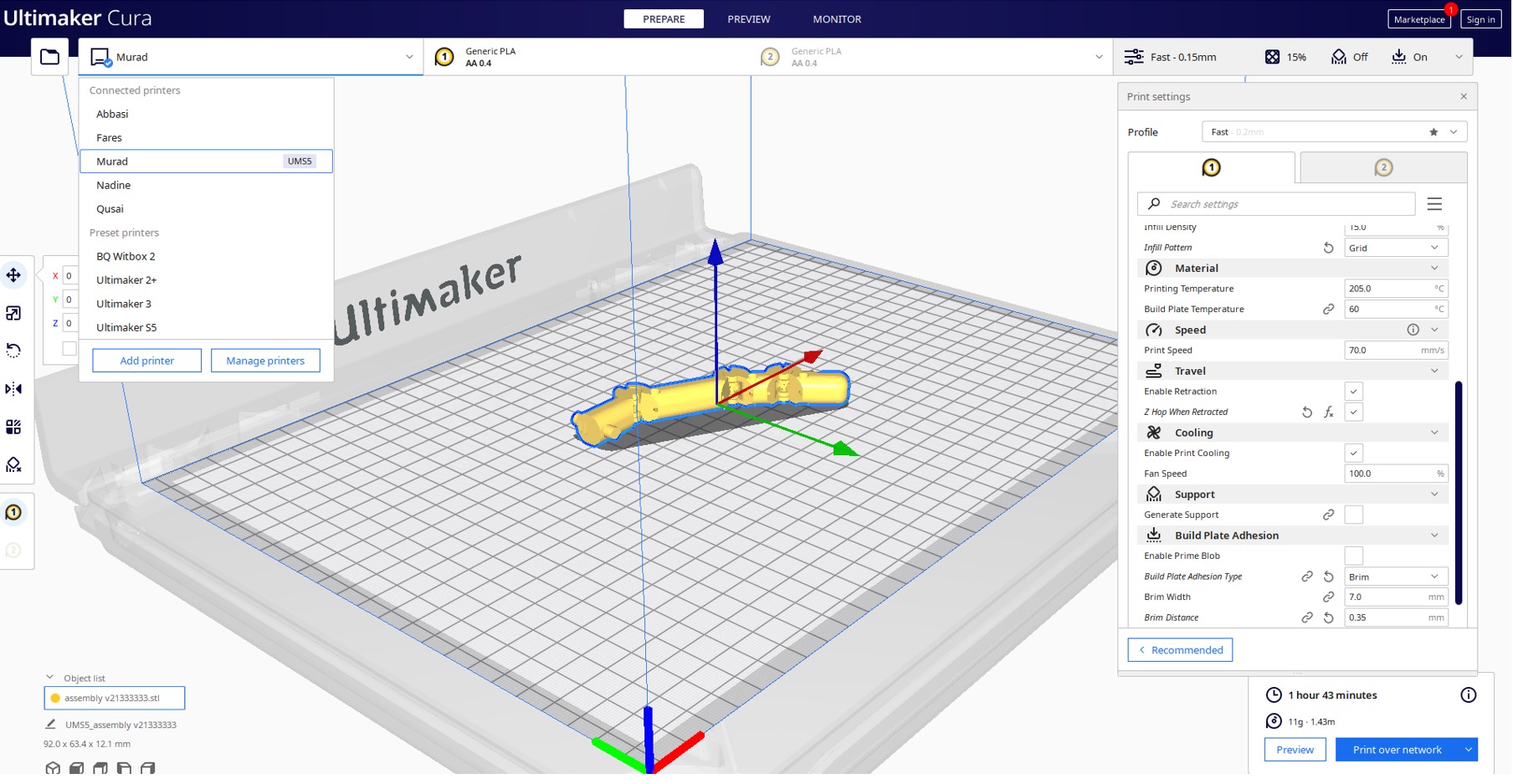
1.3.3 Slicing
The test will be printed in both vertical and horizontal directions in order to discover the effect of direction over Clearance
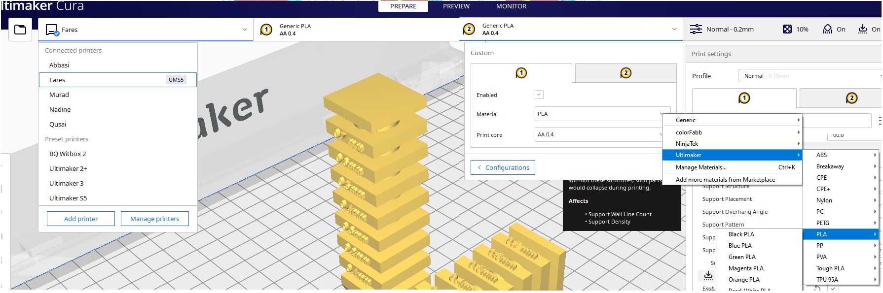
This test was carried out using the settings shown in the images below.
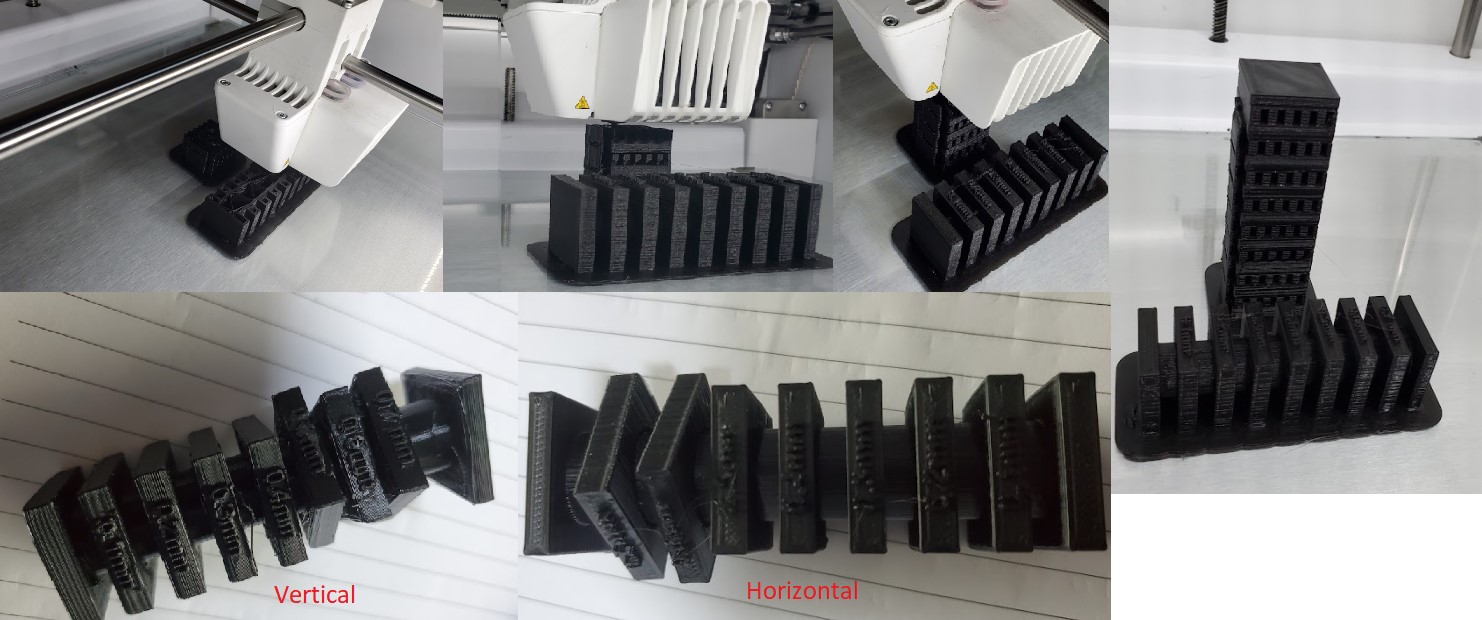
1.3.4 Results
The influence of the direction on the Clearance became obvious. When printing in vertical direction, the clearance required to move a ring on the shaft was 0. 5 mm, whereas it was 6 mm in horizontal direction.
1.4. Unsupported Overhangs, Bridging and Angle, Tolerance.
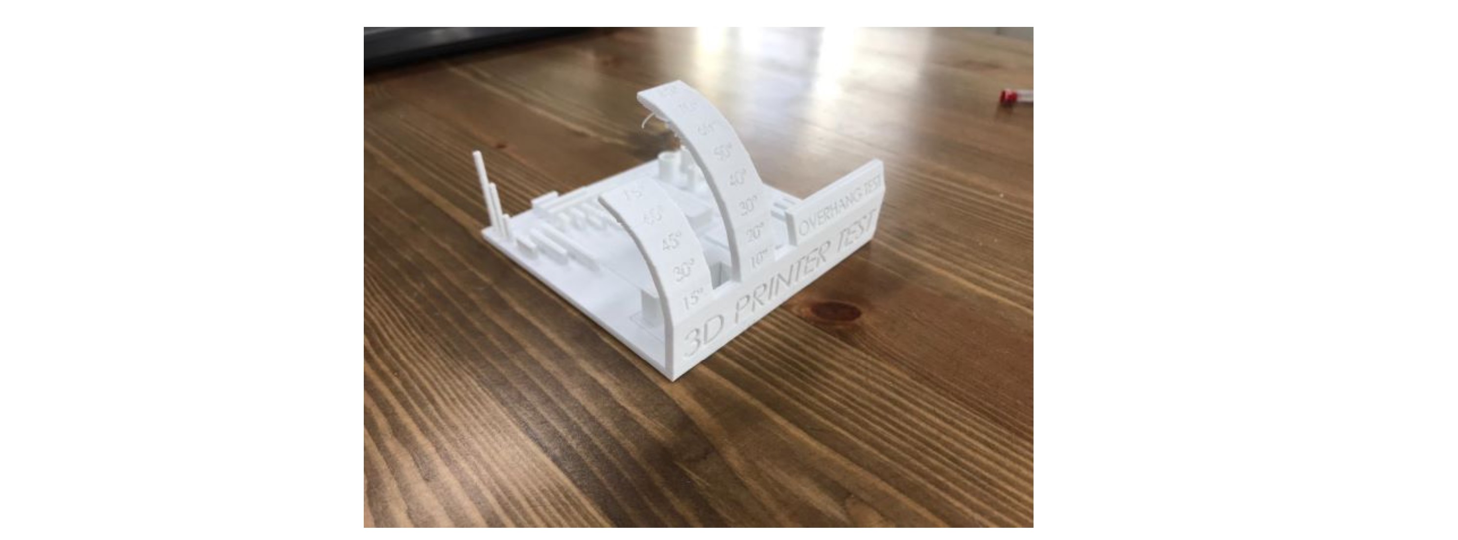
Unsupported Sculpting, Overhangs, Bridging, Angle, and Tolerance are all part of this popular 3D printer test. It's available on the Thingiverse website.
1.4.1. Download file
Unsupported Overhangs, Bridging and Angle, Tolerance test.stl
1.4.2. Design
You can view the tests mentioned in the figure below
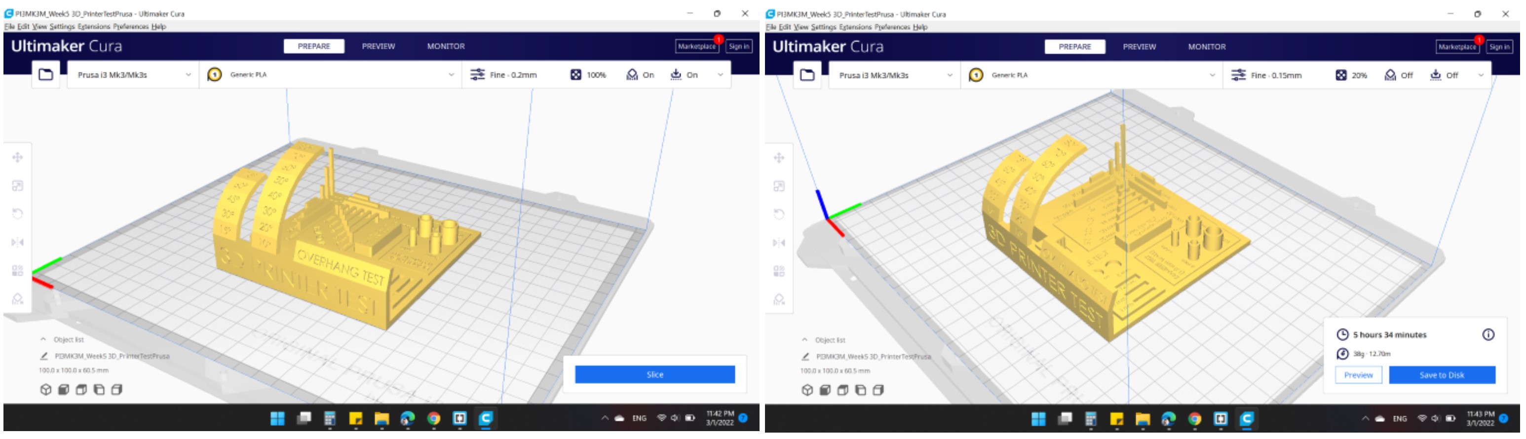
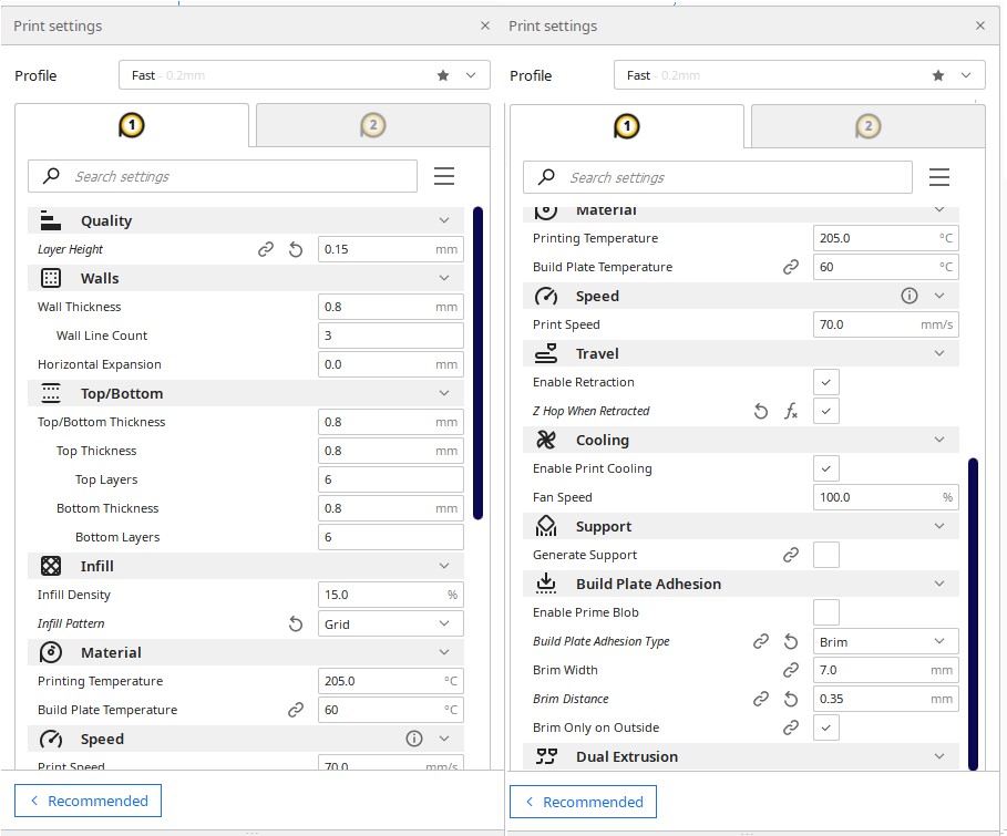
1.4.3 Slicing
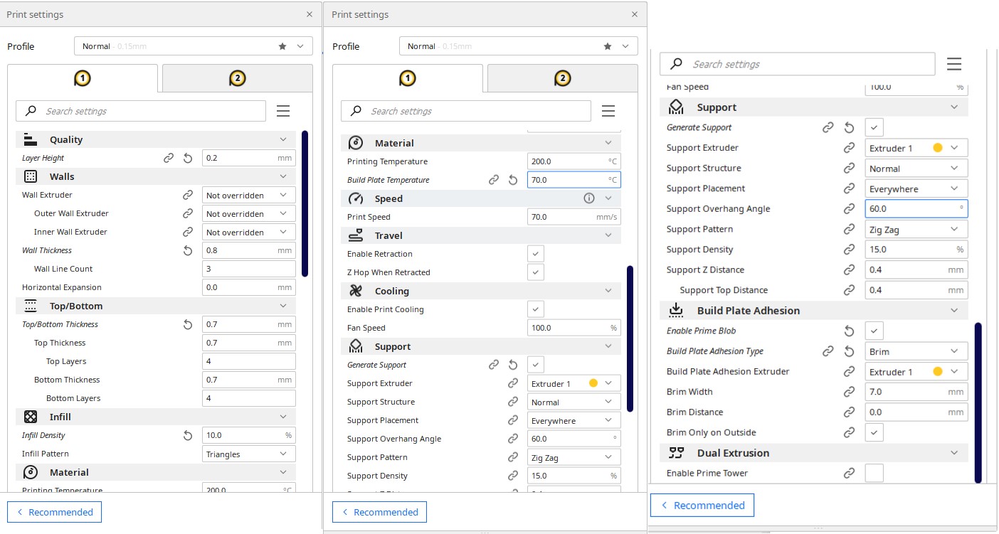
All settings have been made as defaults:
Quality
Layer Height: 0.15 mm. (The height of each layer in mm)
Walls
Wall Thickness: 0.8 mm. (The thickness of the walls in the horizontal direction)
Infill
Infill Density: 20 %. (Adjusts the density of infill of the print)
Infill Pattren: Grid. (The pattern of the infill material of the print)
Travel
Enable Retraction: "YES". (Retract the filament when the nozzle is moving over a non-printer area)
Z Hop When Retracted: "NO". (The build plate is lowered to create clearance between the nozzle and the print)
Support
Generate Support: "NO". (Generate structures to support parts of the model which have overhangs)
Build Plate Adhesion
Build Plate Adhesion Type: Skirt. (Different options that help to improve both priming your extrusion and adhesion to the build plate. Brim adds a single layer flat area around the base of your model to prevent warping)
The model needs:
5 hours 34 minutes
38g
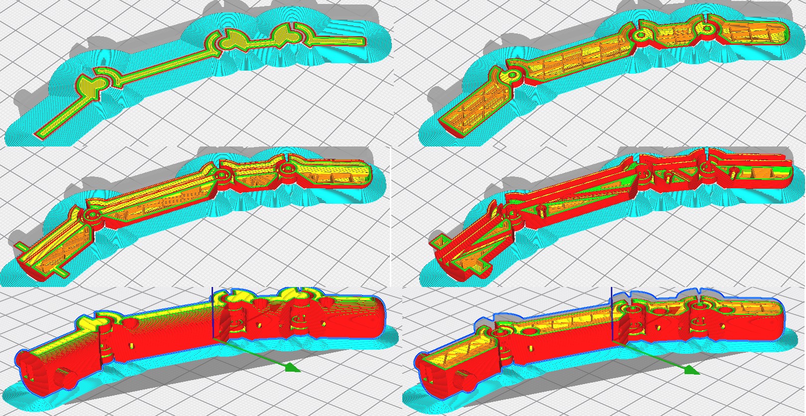
1.4.4 Results
All print settings are within the acceptable range, and some strings may be seen after the angle of 60 degrees.That's normal because we require support to carry the item over an angle of 60 degrees.
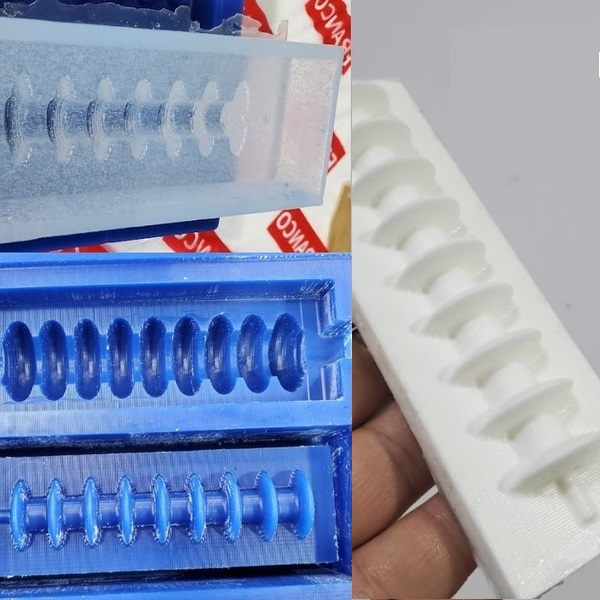
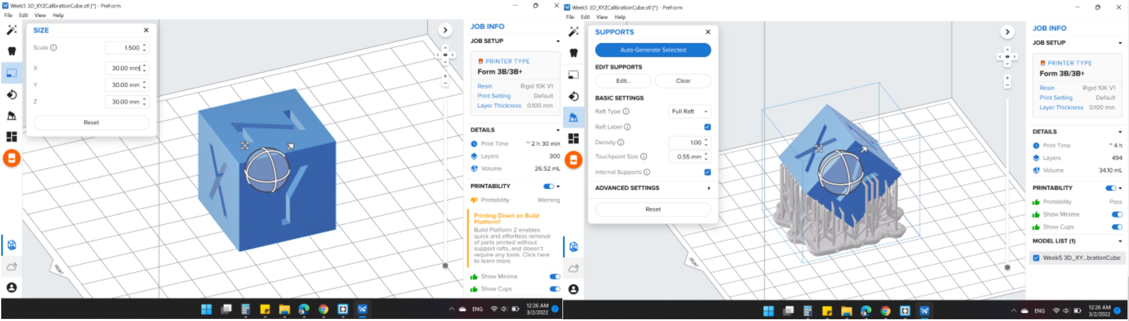
1.5. Tolerance test in SlA
To determine the tolerance, we used an XYZ Calibration Cube. We also increased the scale to 1.5 in order to achieve a 30 mm scale.
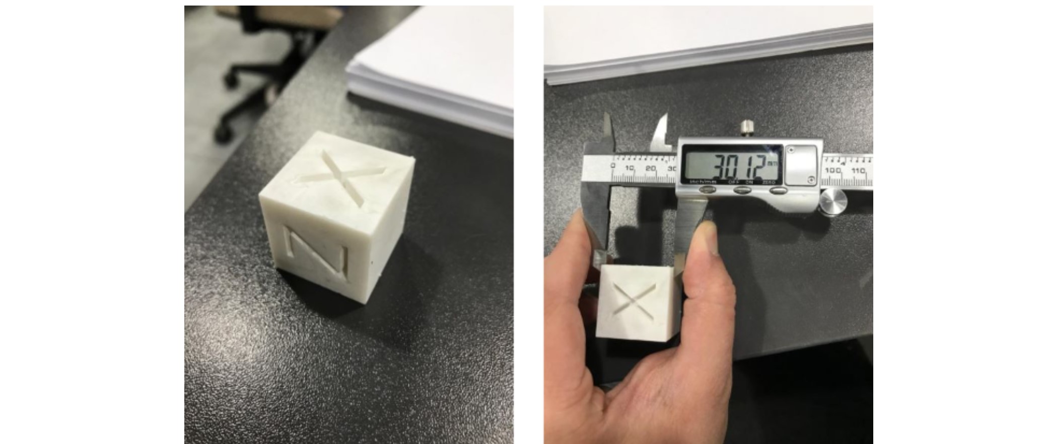 The cube is 30 mm in size, and we measured it with a caliper and obtained 30.12 mm. As a result, the tolerances are 0.12.
2. Individual assignmentt
-Design and 3D print an object (small, few cm3, limited by printer time) that could not be easily made subtractively
-3D scan an object, try to prepare it for printing (and optionally print it)
2.1 3D Scanning
3D Laser Scanning is a non-contact, non-destructive technology that uses a line of laser light to digitally capture the geometry of physical items. From the surface of an object, 3D laser scanners create "point clouds" of data. In other words, 3D laser scanning is a method of capturing a real object's exact size and shape into a digital 3-dimensional representation in the computer world.
2.1.1. Download file
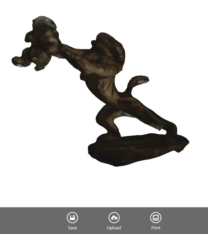
Scan Results
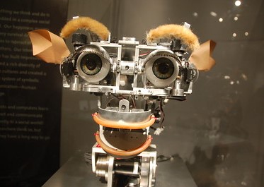
In this section, I used the Sense 3D scanner and the Sense program to scan a medium object. The scanner and the thing I scanned are seen in the image below.
Step 1: Open the Sense software for the Sense 3D scanner . Choose the scan type (Person or Object), then the size of the object to be scanned.
Step 2: If possible, mount your object on a spinning base. Placing the scanner in front of the object is a good idea. Move forward and backward until you get a clear view of the object and a green rectangle around it. Ascertain that the object is centered on the software screen's circle. Maintain your position while holding the scanner. Request that your colleague tap the "Start Scan" button.
Step 3: Have your colleague slowly spin the base until it has completed a complete turn. When it's finished, click "Next" to complete the scan and go to the next stage. The scan is now hollow and has to be cemented. To fill in the scan, click "Solidify." "Next" should be selected.
Step 4: Draw a straight line at the bottom of your scanned object with the "Trim" tool to ensure it has a flat basis for 3D printing. "Next" should be selected.
Step 5: Select a file type and click "Save." My scan was saved as an STL file.

2.1.2. Results
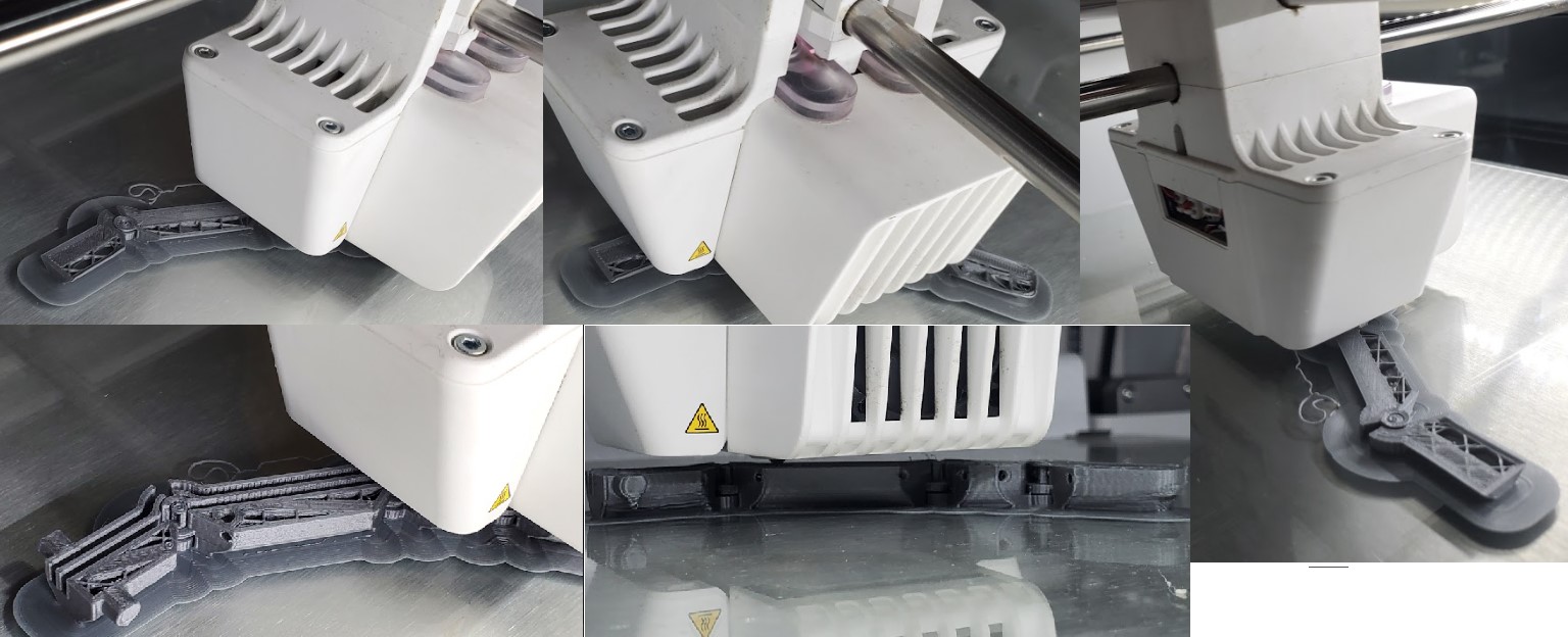
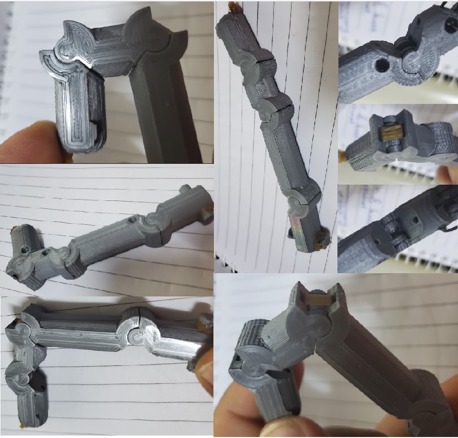
2.2. Print finger in one stage use FDM.
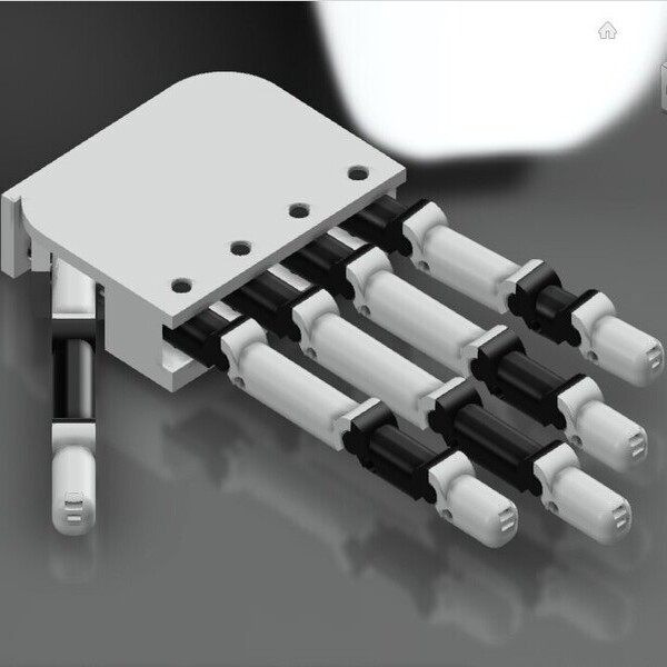
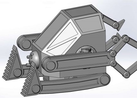
The finger is the main part of my final project as it is designed to be printed in one stage. The finger was designed and drawn in the CAD week. The possibility of printing the finger in this way is an important stage as it gives an indication of the possibility of printing the entire hand in one stage.
2.2.1. Download file
2.2.2 Design
You can see the modeling steps in the CAD week, the main thing that was adopted by drawing that the amount of tolerance is .5 mm to get a smooth movement of the joint.
2.2.3 Slicing
The printing was done with the same settings that the Tolerance test was performed on to get a similar result, because the amount of Tolerance depends on the printing settings, especially the layer height and the nozzle diameter.
2.2.4 Results
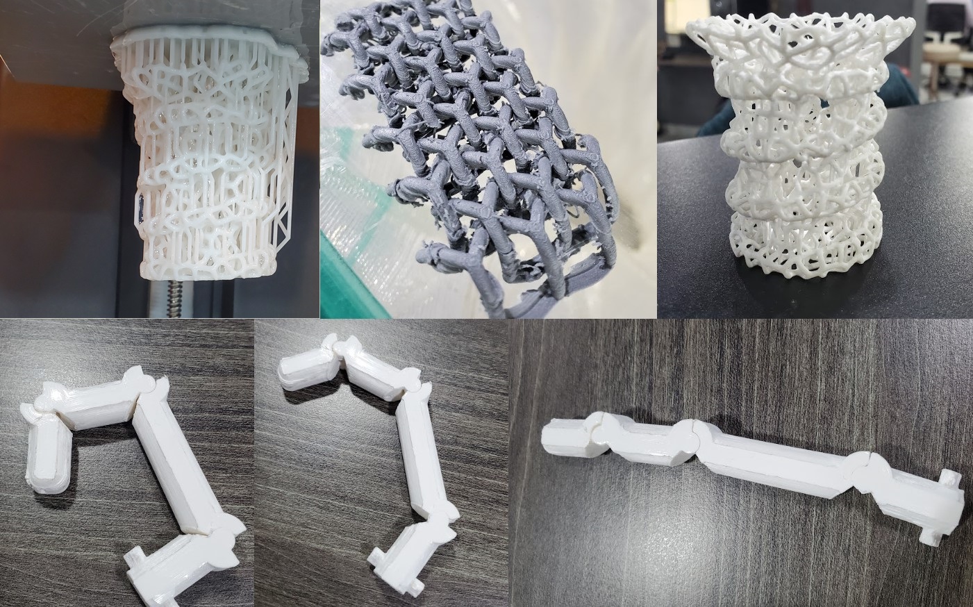
The result was great, the joint movement was good and the internal channels were open. This means that we can move on to the second stage, which is to start designing the hand.
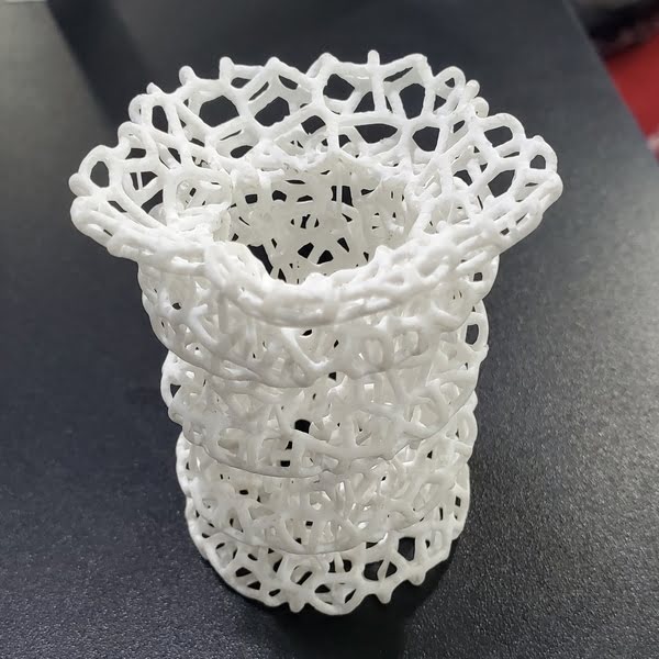
2.3. Print Pencil Container use SLA.
In addition to the finger, I wanted to use the 3D printer to print an aesthetic shape that contains a lot of details, so I started designing a pen container. One of the easiest ways to get a beautiful Voronoi shape is to draw a solid body and save it in stl file, then make it in voronator website.
2.3.1. Download file
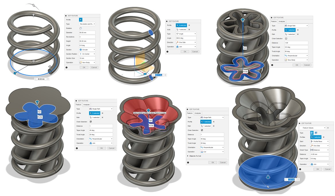
2.3.2 Design
Step one : open Fusion 360, then go to Create, then to Coil.
Step Two: Draw a circle at the beginning and end of the circle and make revolve to close the beginning and end of the coil.
Step Three : draw a rose at the bottom and make an extrode twice once with twist angle and once with a taper angle.
Step Four : After obtaining the solid shape, export the file in stl format and upload it to the voronator website.
Step Five: Click on start and then download the file.

2.3.3 Slicing
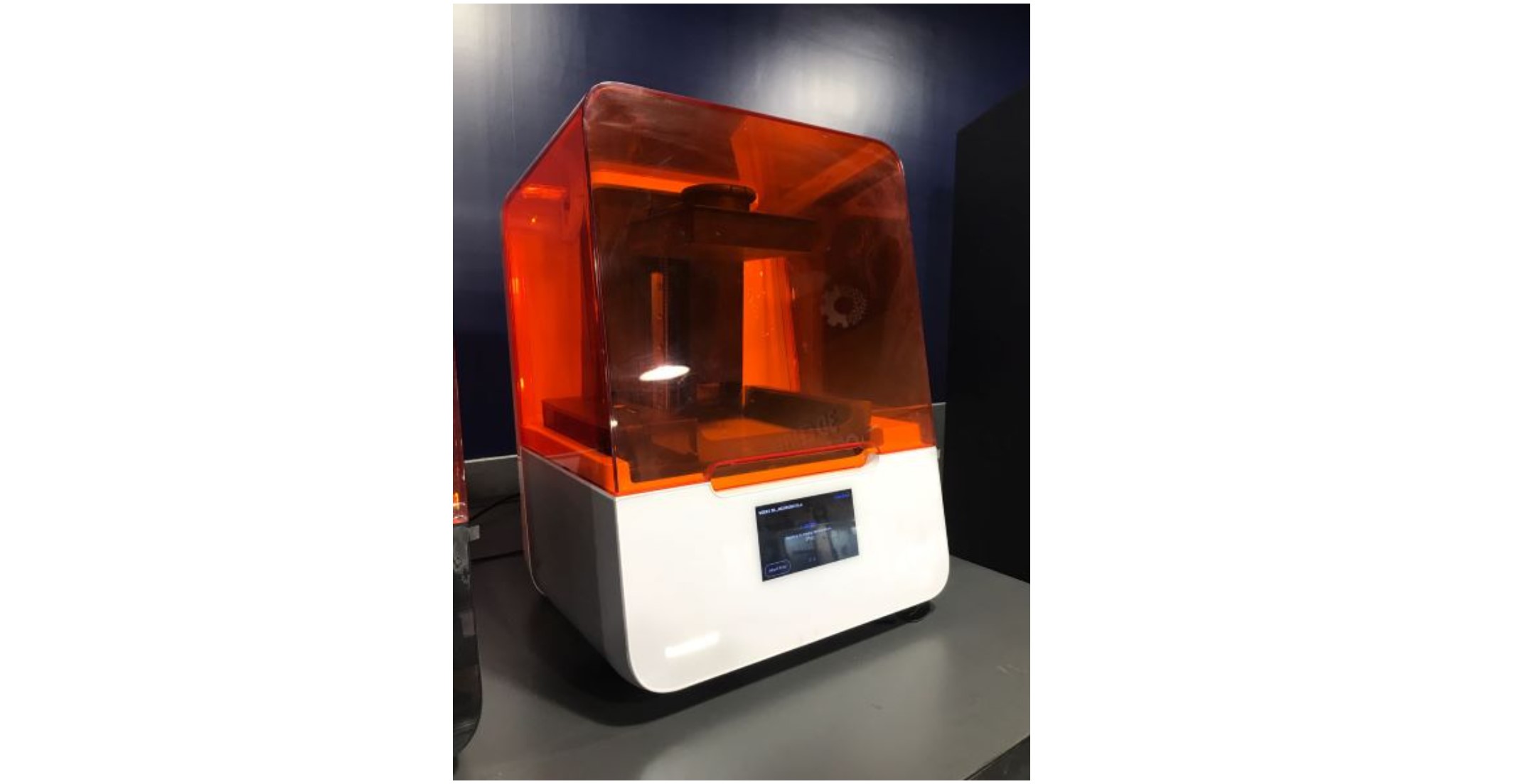
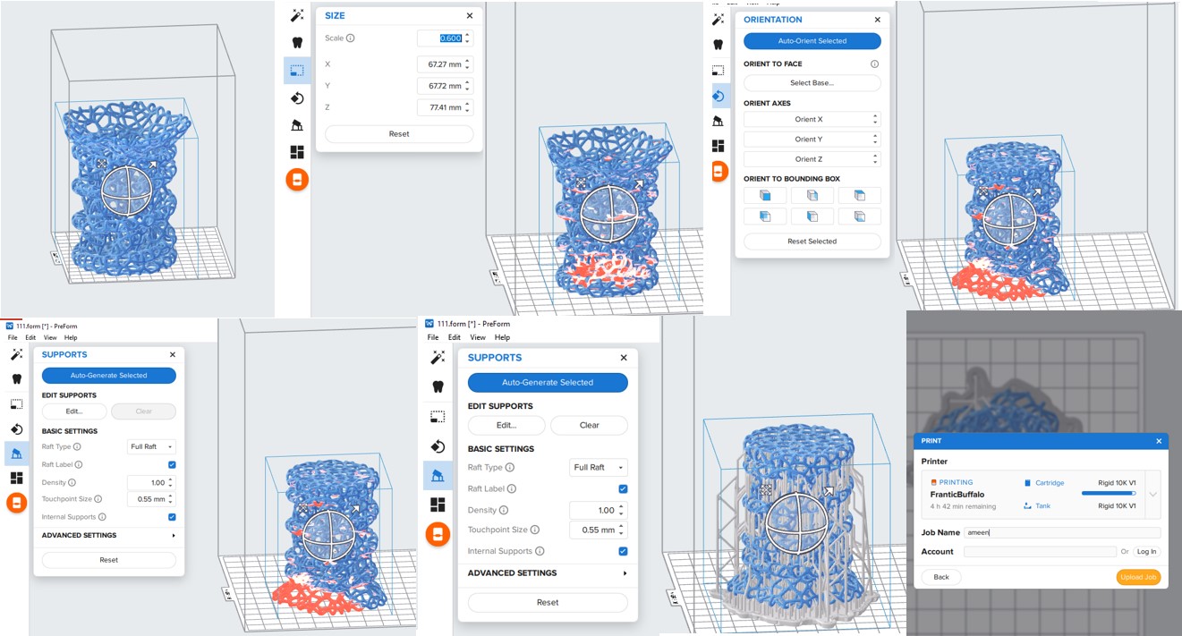
Stereolithography (SLA) is the technology that was used. SLA is a 3D printing technique that uses a light source to solidify a liquid (photopolymer) resin to produce 3D printed structures.To print an object, the print bed is dipped into a resin-filled tank, after which a laser plots each layer of the object and passes through the tank's bottom, soldering it. The construction platform moves a bit to the top after each layer, allowing more resin to flow into the following layer.
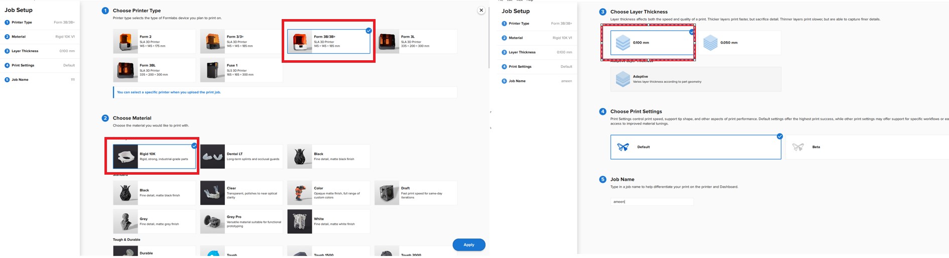
Open the stl file and began putting the settings in place. The first step is to reduce the size of the model. Then, to auto-generate support, press the magic wand.
Note: After a while, the print bed should be replaced; the program flips the model to take up the least amount of space on the bed possible, preventing the bed from dying.
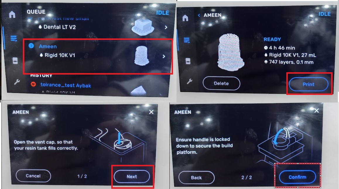
The material was then changed to Rigid 10K, and the layer thickness was reduced to 0.1mm.
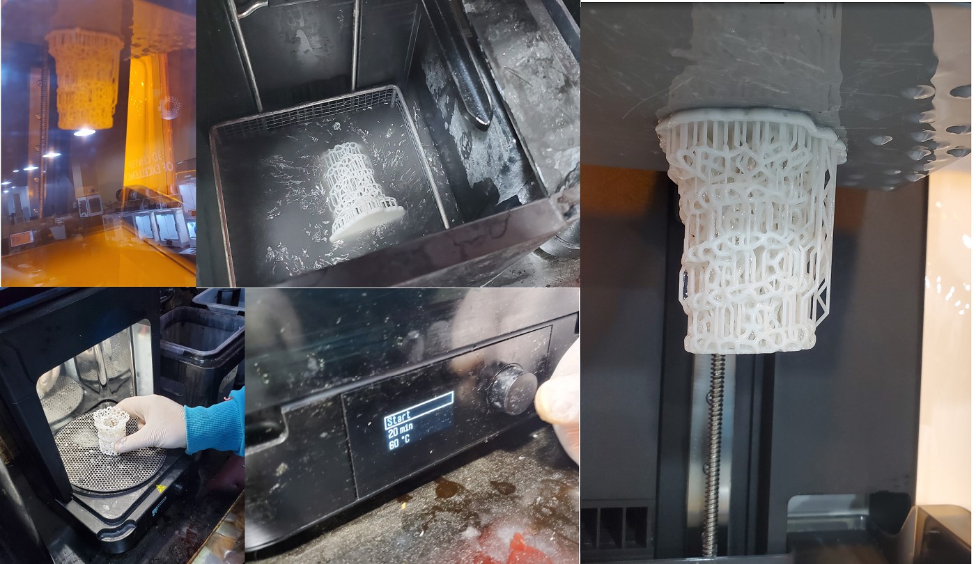
After the printer has finished printing, soak the model in ethanol for 15 minutes to remove any remaining resin.After that, leave it to cure for 30 minutes.
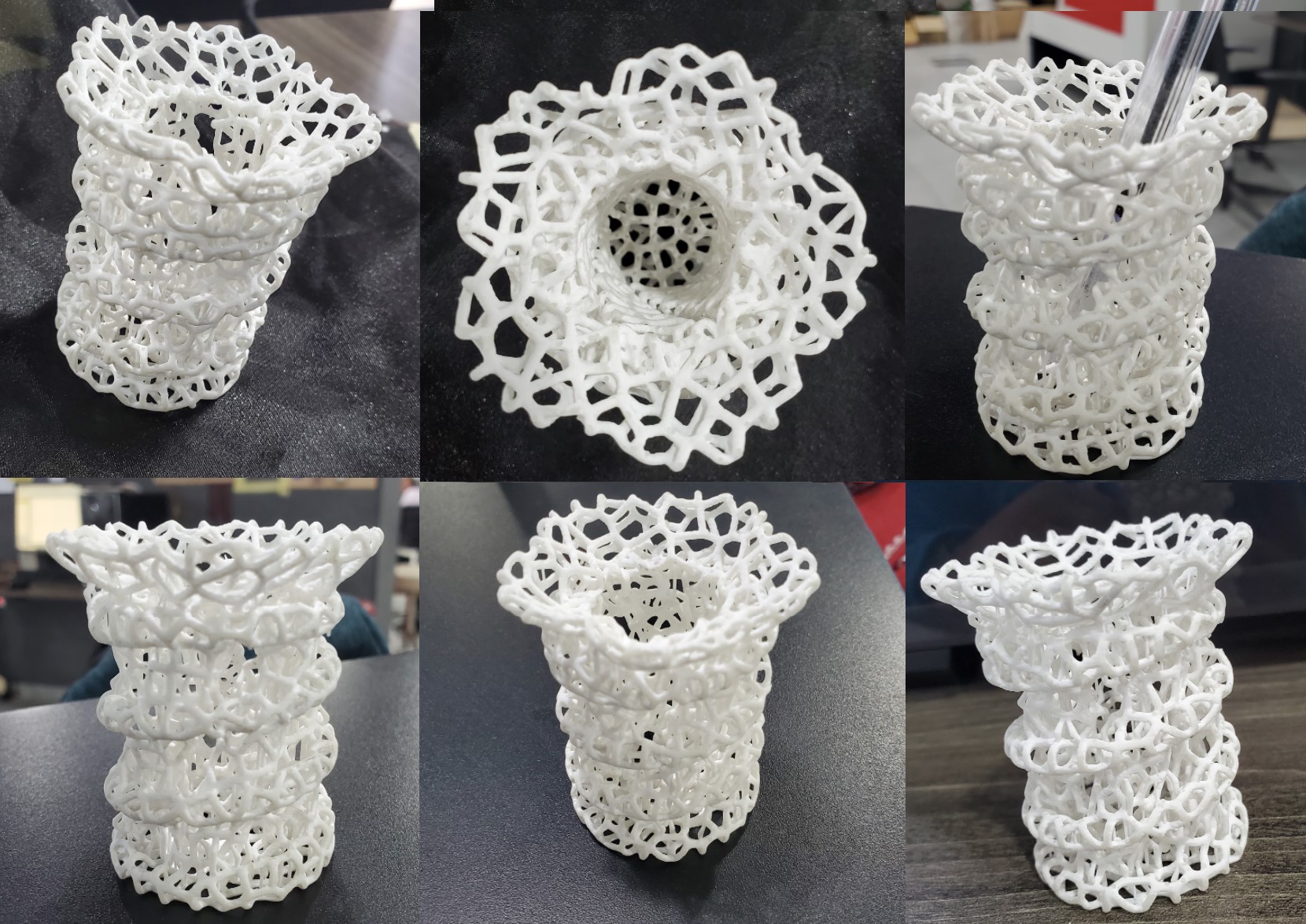
2.3.4 Results
It was a challenge to remove the support because it interferes with the model, but if we look at it positively, the remnants of the support have merged with the model so that it is difficult to notice. This added to the piece's attractiveness.
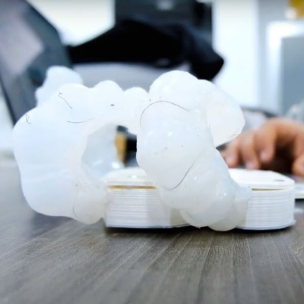
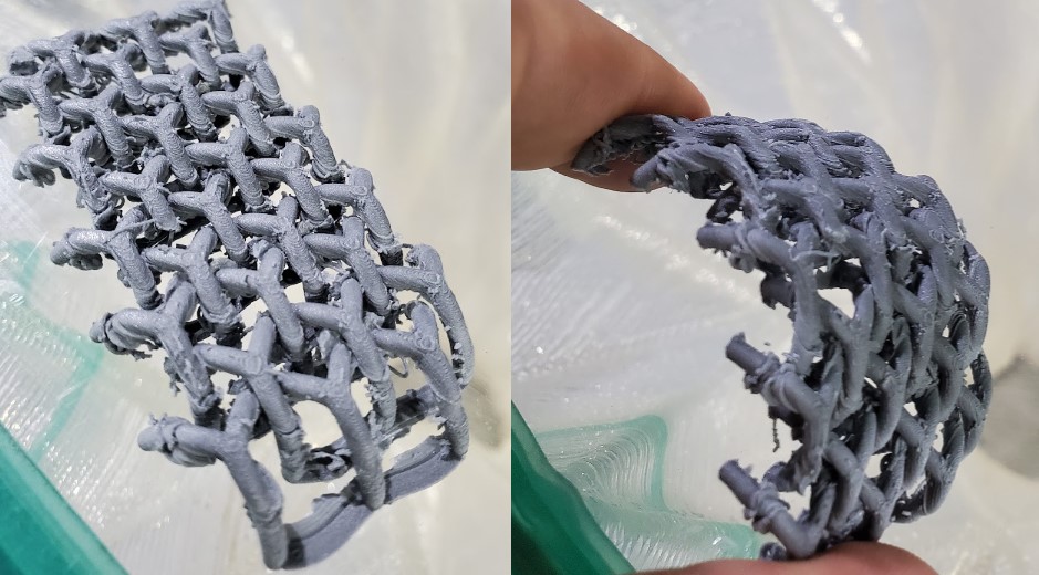
2.4. Print chainmail use FDM.
Chainmail is a type of armor constructed of small rings that are linked together to resemble fabric.It is now possible to make it with 3D printers, as long as the connecting rings are designed to be printed together and the design does not require support.
2.4.1. Download file
2.4.2. Design
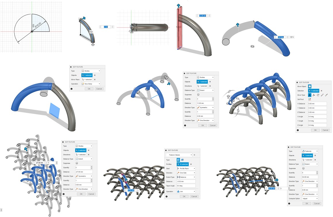
This design depends on one of design rules for 3d printing that the arcs derived from a circle do not need a support, so that these arcs overlap each other, forming a chainmail.
The pictures below show the steps for modeling Chainmail, where you start by drawing a quarter circle, then sweep, then cut one end at an angle of 120, then make a pattern to get three pieces, then start repeating the piece to get Chainmail
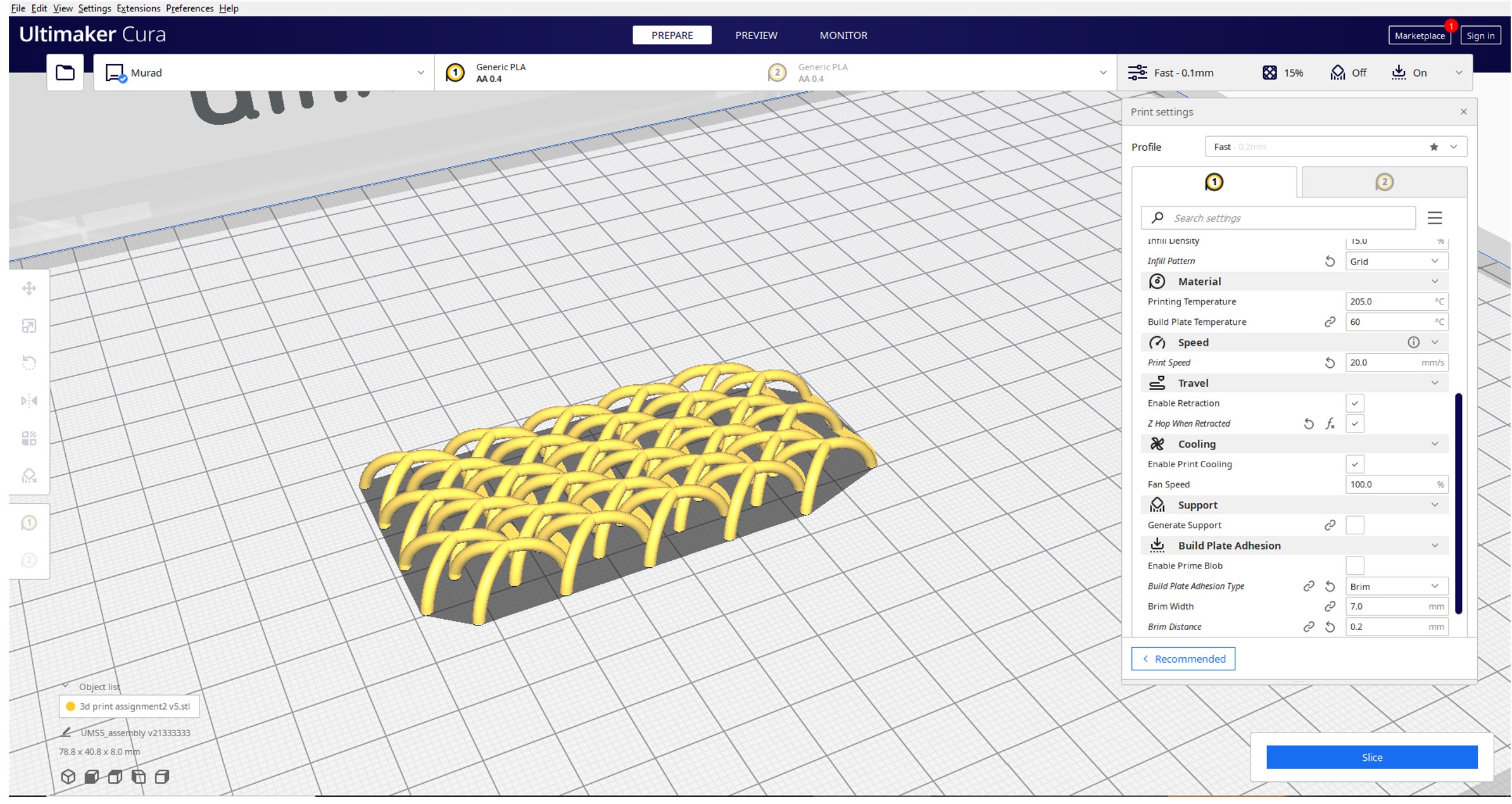
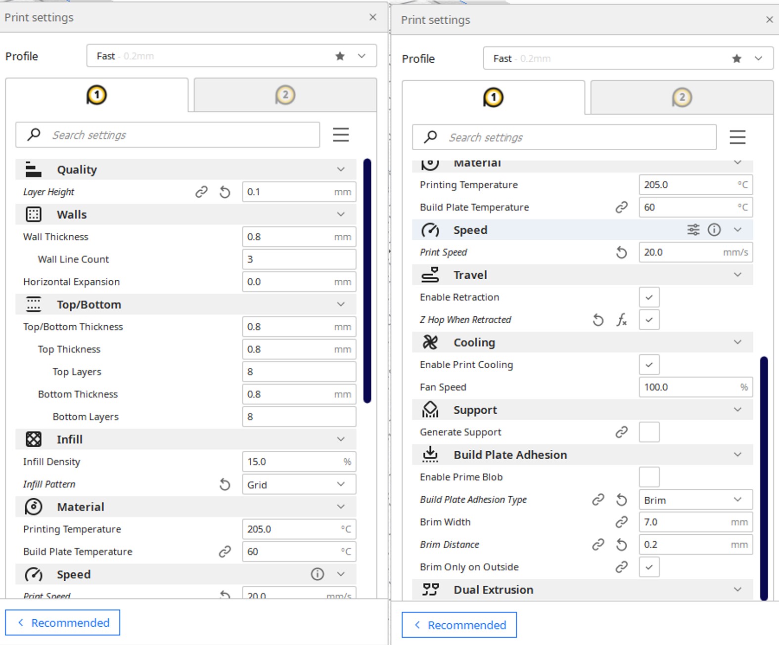
2.4.3 Slicing
This chinmail printing is considered one of the critical things, Because the area of adhesion between the piece and the bed is small, the first brim should be activated to hold the piece on the bed, and the printing speed should be reduced to 20 mm/s because the printing is intermittent greatly (when the 3d printer builds a layer, it needs to make a lot of separate circle), resulting in significant vibration and instability.
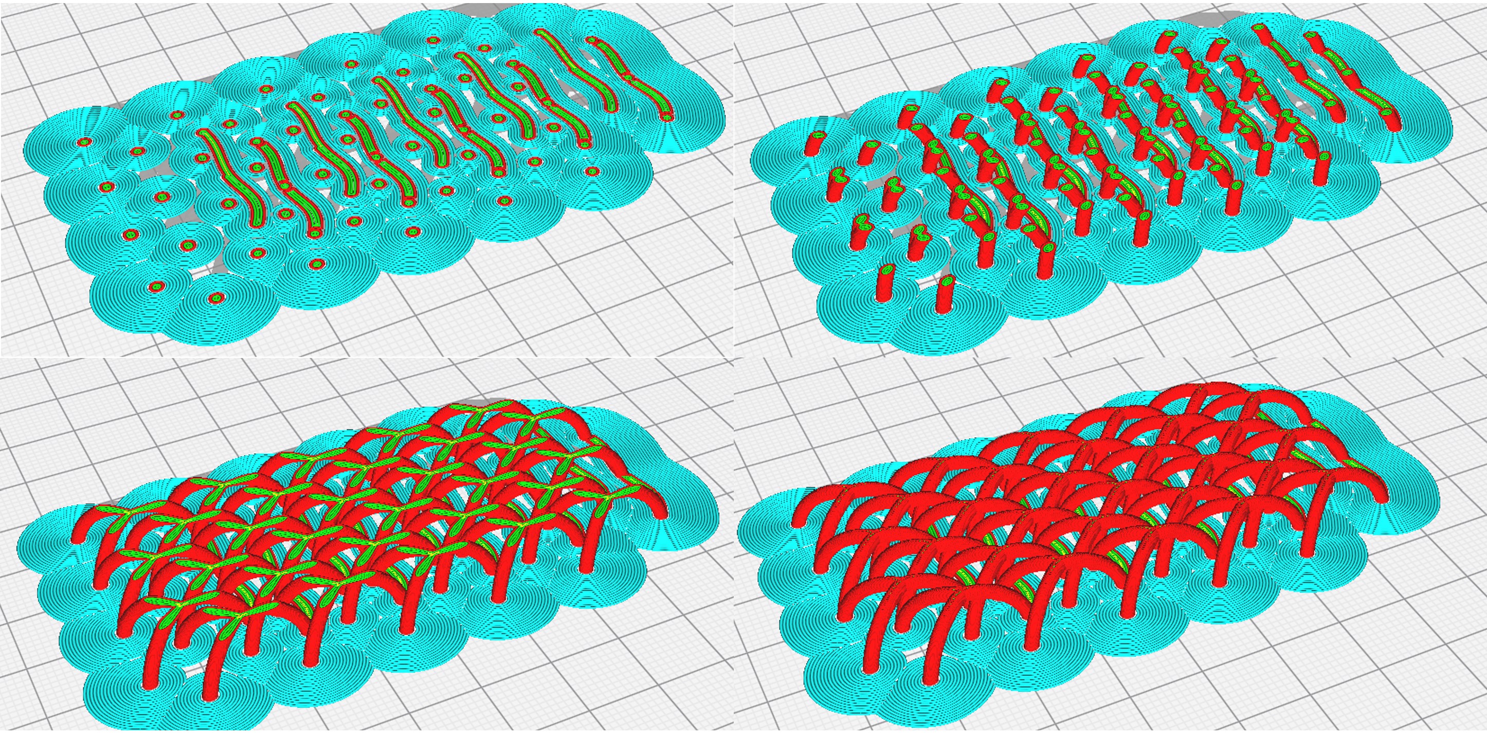
2.4.4 Results
Although the surface finish is not perfect put the pieces have good flexibility.
3. Hero shoot!