Computer-controlled machining
1. Group assignment
Complete your lab's safety training Test runout, alignment, speeds, feeds, and toolpaths for your machine Document your work to the group work page and reflect on your individual page what you learned
1.1. Machine Overview
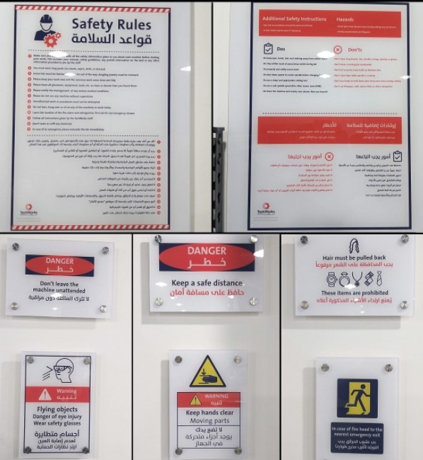
Safety
When dealing with CNC router machines, safety precautions and procedures must be taken into account. All caution signals should be read, understood, and followed.
The ShopBot PRSalpha ATC 96-60-8 is a full-sized gantry tool that can be used to CNC cut, drill, carve, and machine wood, plastic, aluminum, and other materials.
Machine: ShopBot PRSalpha ATC 96-60-8
Software: VCarve Pro
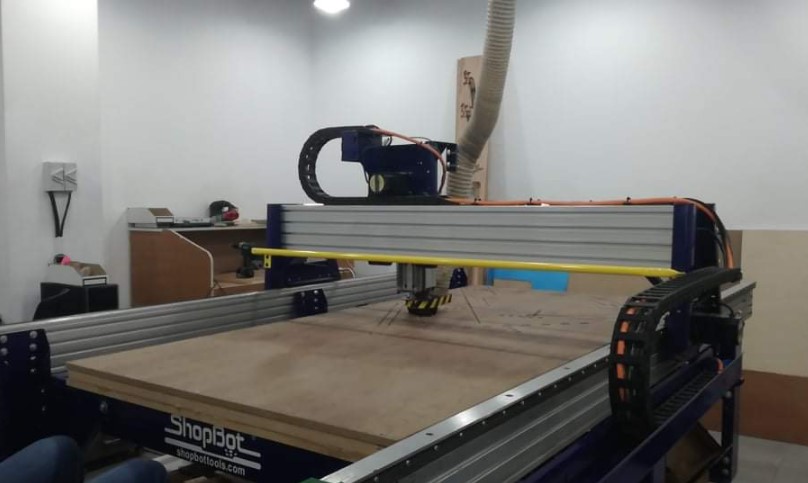
Specs: Working Area (Length x Width x Plunge): 105” x 61” x 8” (2.67m x 1.55m x .2m)
XY Move Speed (with full cutting force): Max 360”/min (9.1m/min)
Z Move Speed (with full cutting force): Max 120”/min (3m/min)
Step Resolution: 0.0004” (0.010mm)
Positional Repeatability: +/- 0.002” (0.051mm)
Spindle RPM: Max 18,000 RPM
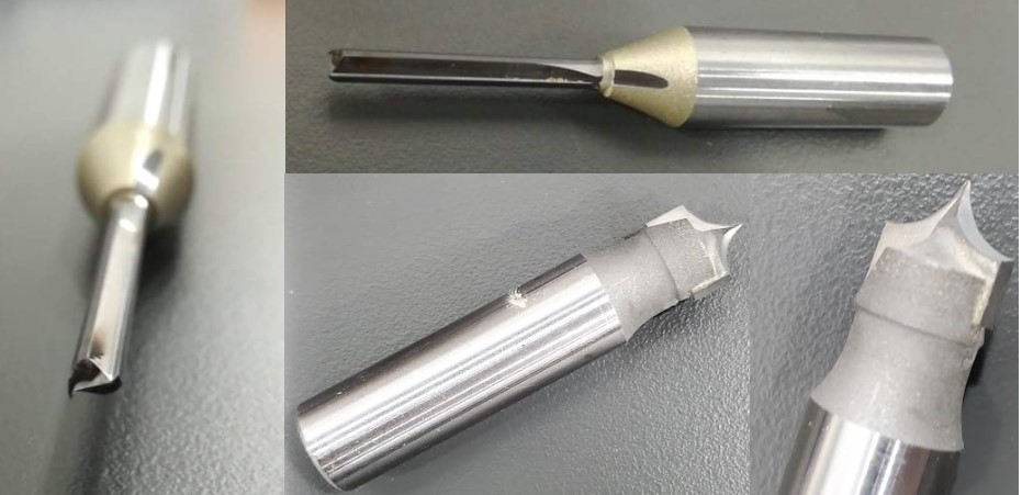
1.2. Tooling
We examined many types of endmills visually before using two of them. Radius Cutting Tool and straight 4mm endmill , ball nose, and tapered ball nose endmills were all examined. Each was created with a unique function in mind, and they can all be utilized in a CNC router.
1.3. Feed Rate & speed
To compute the feed rate and rotation speed, we used the manufacturer's Cutting Data Recommendations ("Feed rate is the speed at which the cutter encounters the component and is commonly defined in units/minute"). The data for MDF, which is equivalent to plywood Recommendations, was used.
2. Individual assignment
Make (design+mill+assemble) something big.
2.1. Design
File to download.
3D Model
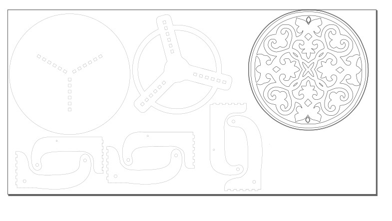
Flouting table.dxf
Flouting table.svg
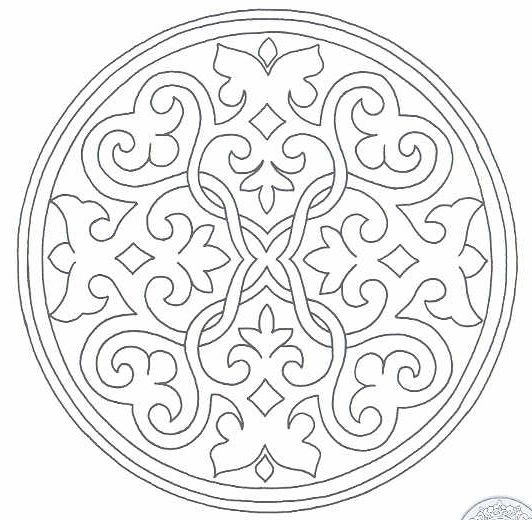
Pattern.jpg
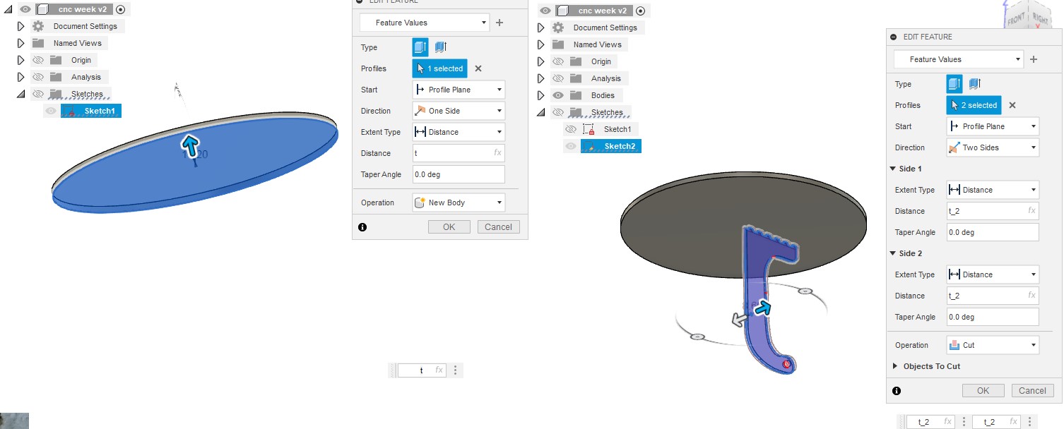
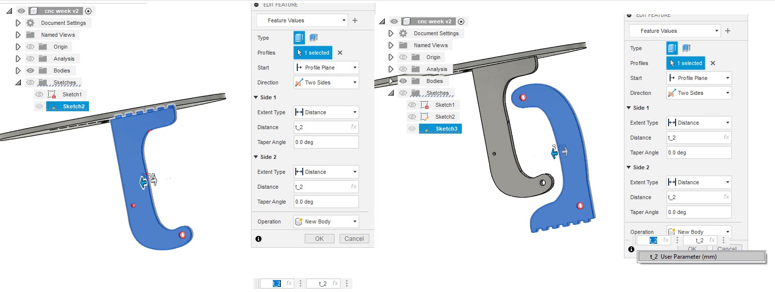
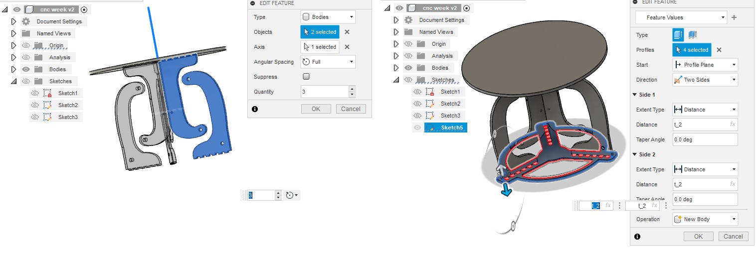
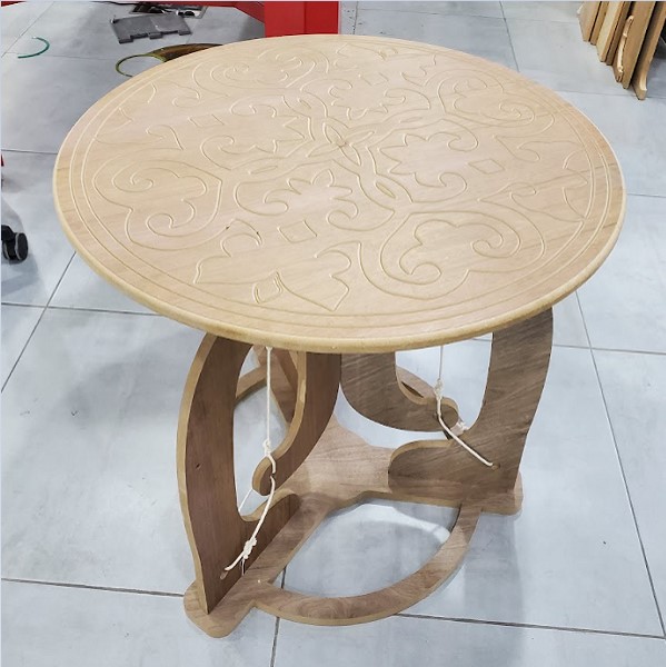
I created a floating table for this assignment. For parametric design, I utilized Fusion 360 and defined the thickness as variables.
To create the tables, I used 17.0 mm MDF wood with a walnut sheet on it. A caliper was used to measure the thickness, which came out to 17.2 mm. In design and machine software, the actual size should be used. There are eight part in this package.
The table is made up of four sketches: one for the top, another for the bottom, and two more for the legs. The variable "t," which determines the thickness of the wood board, controls the extrusion height.
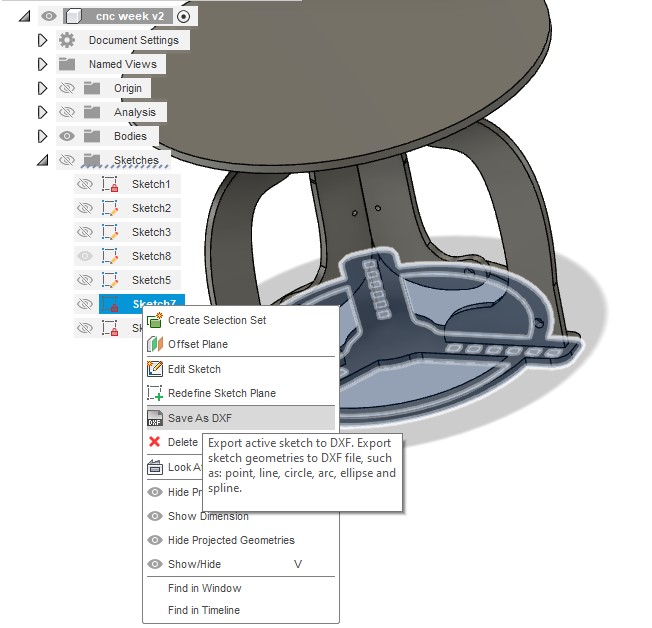
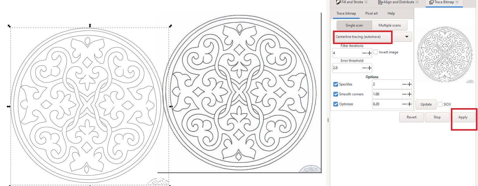
I saved the sketches as dxf files and imported them into Inkscape after finishing the 3D model. I used Inkscape to engrave table tops and figure out how many pieces a single board (2440mm x 1220mm) could hold. I drew a boarder and manually nested it, assuming a 30 mm boarder gap. I saved the file as dxf after finishing my work in Inkscape. note : you can know how to make trace bitmap from CAD week.
2.2. Mill
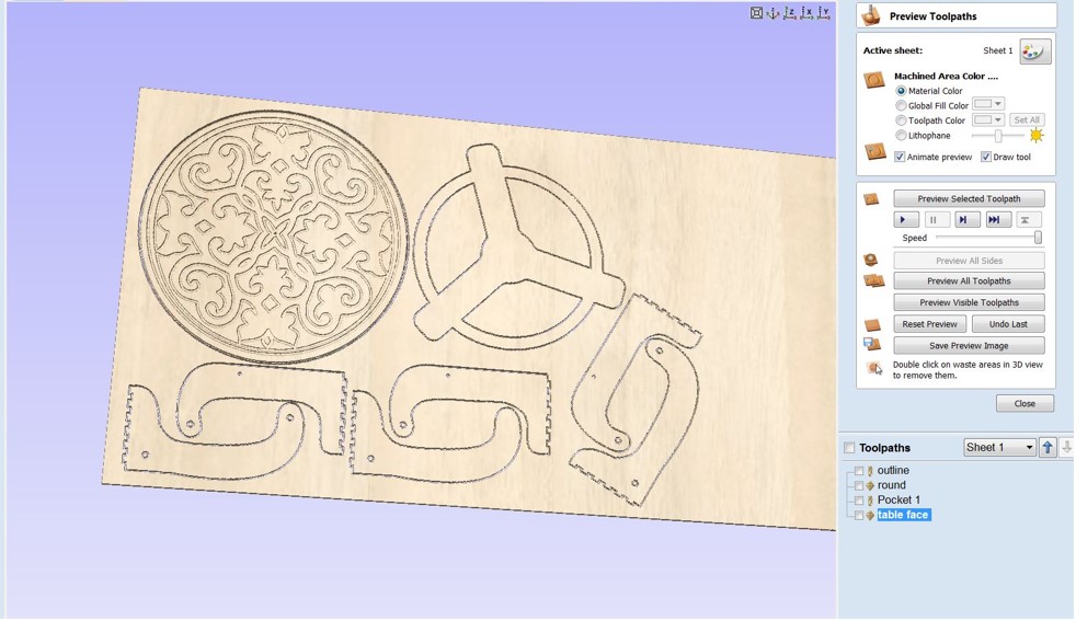
Working on VCarve Pro
File to download.
Floating Table.crv
Pocket 1.sbp
outline.sbp
round.sbp
table face .sbp
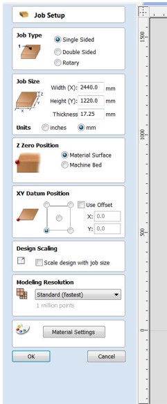
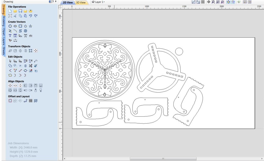
Step 1: Open VCarvePro and select "Open an existing file" from the File menu. Locate and open the floating Table.dxf file. The Dxf file is shown, and the "Job Setup" menu appears. Click "Ok" after you've entered the job settings. The board I used measures 2440mm x 1220mm and is 17.2mm thick.
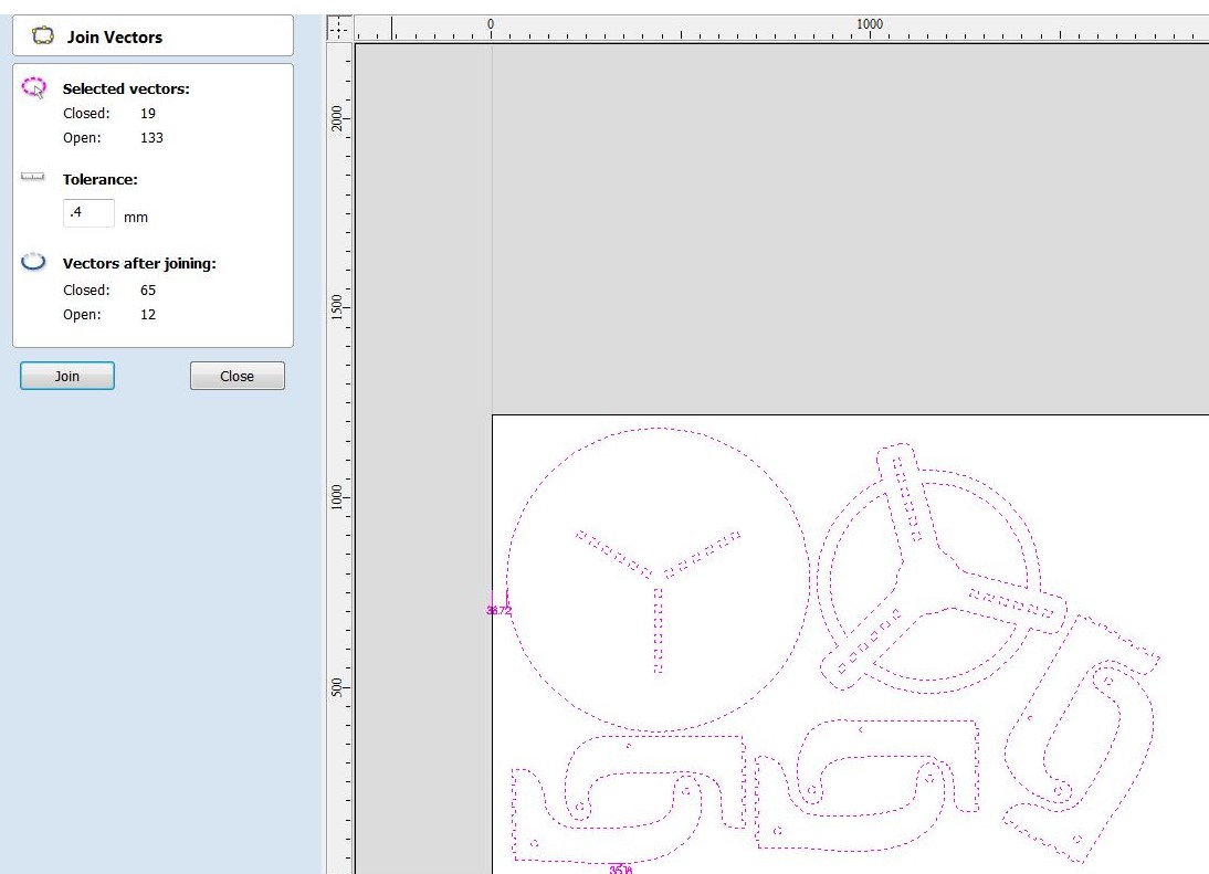
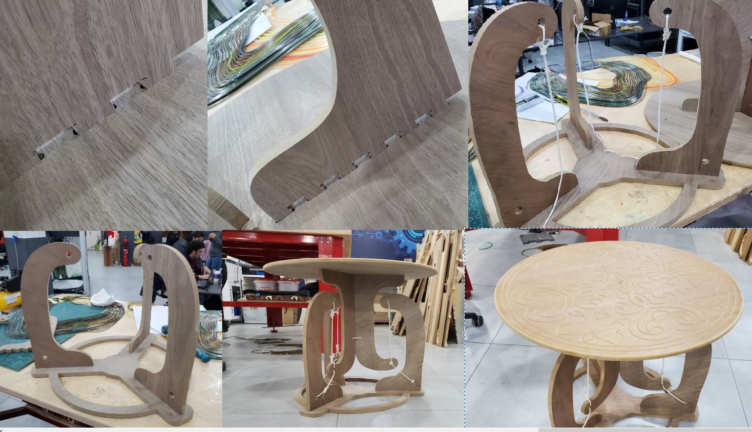
Step 2: Select all of the objects and then choose "Link - join open vectors." This will join the lines and curves in each item, allowing it to be regarded as a single toolpath. Because there are greater gaps between things and it is easier to add tabs to keep objects in place while cutting, I prefer manual nesting in this case.
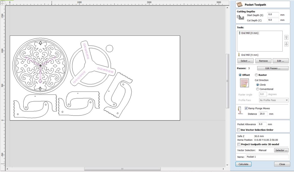
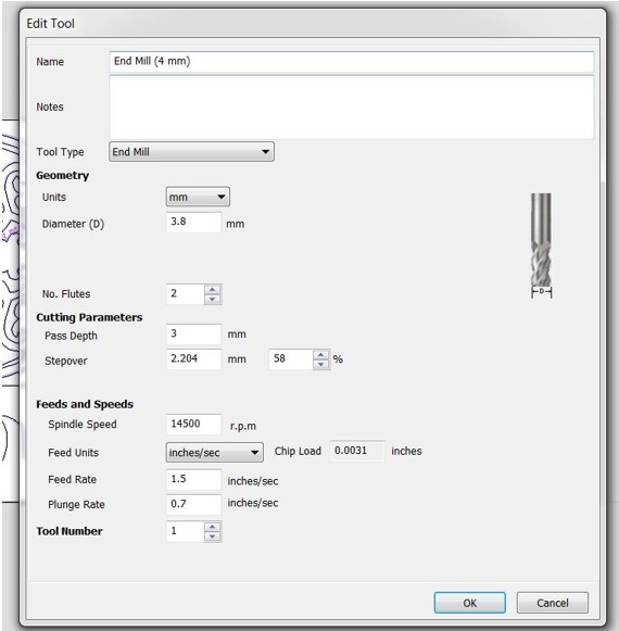
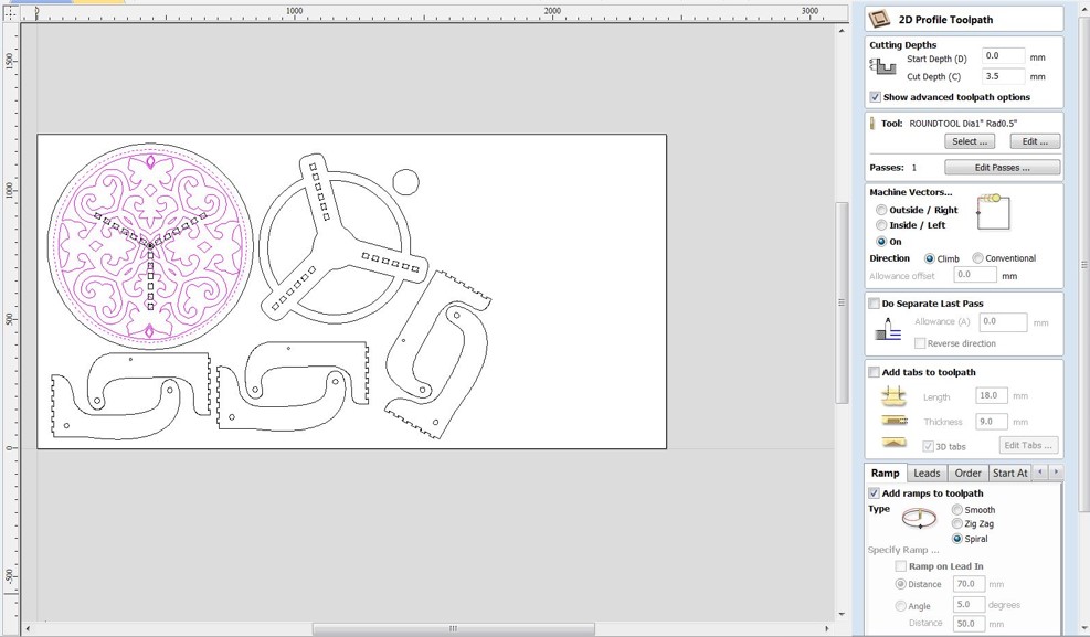
Step 3: Click "Pocket Toolpath" from the "Toolpath Operations" menu. If the endmill is defined in the database, select "Select" in the "Tool" menu and look for "57-287" in the list. Otherwise, you can select "Edit" and set the endmill for this job locally. It's important to remember that you must compute the "Feed Rate" as mentioned in the group assignment. Set the "Plunge Rate" to about 1/3 of the feed rate.
Step 4: Now it's time to work on the joints. Select "Pocket Toolpath" from the "Toolpath Operations" menu. Make sure you're using the 4mm endmill. Set the depth to 9mm in the "Cutting Depths" option. Rename the toolpath after you've completed the other settings. Select all joints using the shift key and then click "Calculate" on the "Table" tab. Click "OK" to dismiss the warning notice.
Note : I put the tool diameter on the software 3.8 for this job to make clearance = 0.1mm
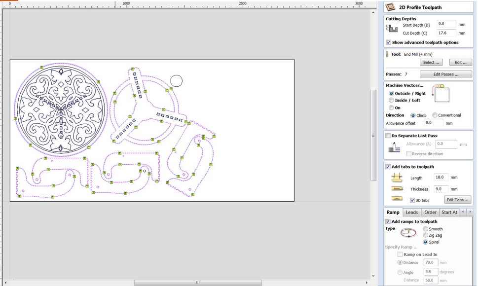
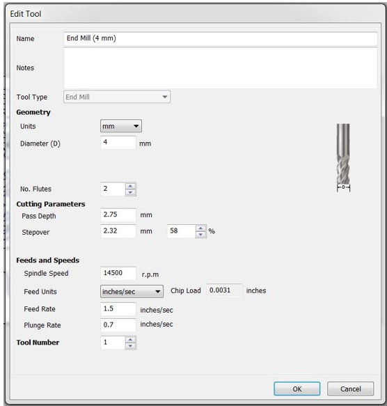
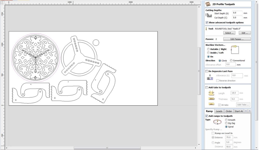
Step 5: Select "Profile Toolpath" from the "Toolpath Operations" menu. Make sure you're using the 4mm endmill. Set the depth to 17.5mm in the "Cutting Depths" option. Select "Out" from the "Machine Vectors" option. Outside the lines, the endmill will cut. Complete the remaining parameters.
To keep each element in place during cutting, we'll need to add tabs between the objects and the board. Shift choose the paths where cuts should be made first. "Add tabs to toolpath" should be enabled, and then "Edit tabs..." should be selected. Select "Constant space between tabs" from the tabs menu and adjust as needed. Select "Add tabs" from the drop-down menu. Using the mouse, review tabs and move away from curves. If necessary, you can also eliminate tabs. Click the "Close" button. Change the tabs' "Length" and "Thickness" and then "Calculate."For the warning notice, select "Yes."
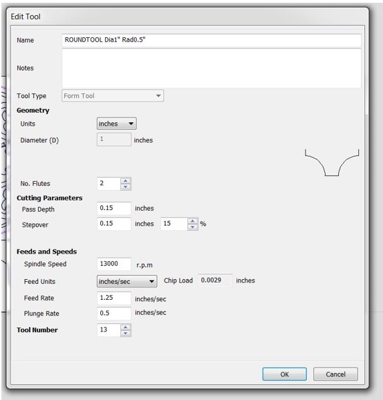
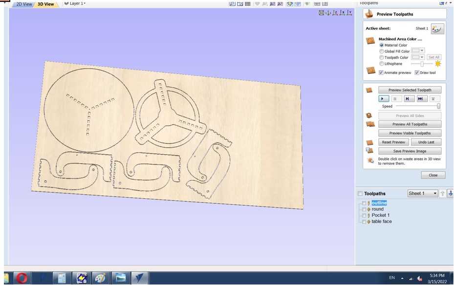
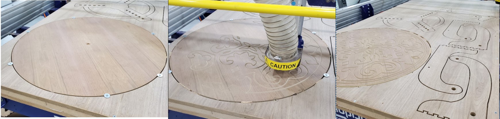
Step 6: In “Toolpath Operations” click on “Profile Toolpath”. In “Tool” menu use the radius tool to engrave trails and round the corners of table tops. Set the depth to 4.0mm in the "Cutting Depths" option. This will be the engraving's depth. Select "On" from the "Machine Vectors" menu. The endmill will travel along the drawn line's center. Click "Calculate" while holding down Shift and selecting engraving paths. A preview toolpaths window appears, allowing you to practice the engraving process.
After job previews if everything is good start saving the tool path by select the tool path and click on save tool path.
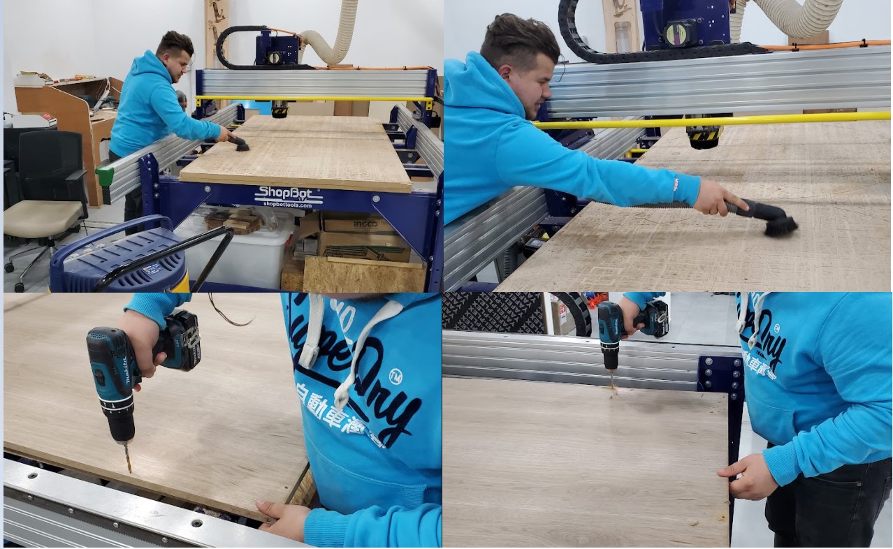
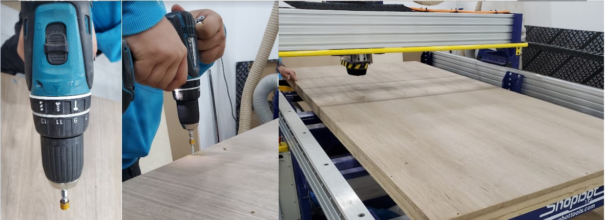
Step 7: Fixing The board
On the bed of the machine is an MDF sacrificial board. If the endmill penetrates the work piece, the sacrifice sheet will be cut twice. This ensures that the machine's body and tool are not damaged. Before installing the board, the sacrificial board must be clean. To fix the work piece on the sacrifice board, holes were drilled in it and wood screws were utilized. When we work on software, we use a 30mm "Boarder Gap" definition. Because this area will not be cut, we can use it to install the screws. If the work piece is misaligned with the machine axes, the boarder gap compensates for the misalignment, and cuts are made inside the work piece.
Change the tool
We used the supplied wrenches to increase safety. One of the wrenches is attached to the "INTERLOCK DISENGAGED - ENGAGED" key by a string as a simple safety precaution in the machine. As a result, whenever you need to use the wrench, you must remove the key, and the spindle will not start. The dust extractor must be removed before the collet can be attached to the spindle.
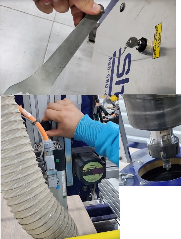
To begin, remove the cover from around the tool, then use the wrenches to loosen the nut and collet a bit, then pull out the old tool. Next, unscrew the collet and nut, clean them, and then reinstall them, tightening them a little. Finally, place the new tool appropriately and tighten it well.
Note:The maximum part of the endmill shank should be put into the collet to ensure good adhesion and minimize tool bending. The end tip of the endmill shank may be flush with the collet, or it may extend beyond the collet end if possible. A safe gap between the cutting edges and the collet face should be maintained at all times.
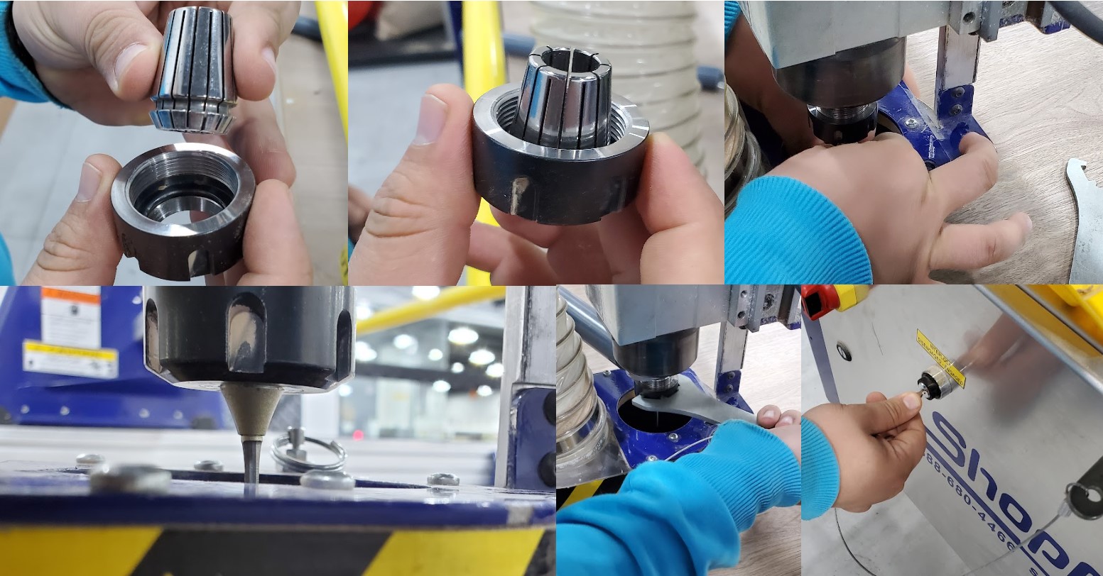
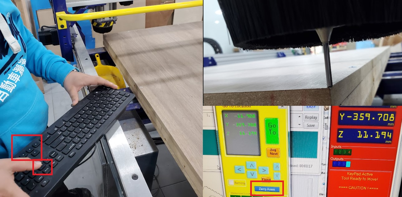
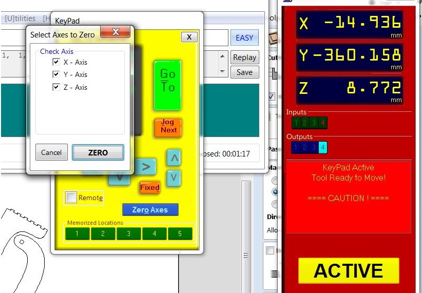
The X-Y-Z axis should be zeroed after the board has been fixed. Move X and Y to the corner of the board and get down in Z-Axis antil touching the board, then click on zero axes, check x-y-z, and select zero.
Note: The Z-Axis should be zeroed again after changing the end mill.
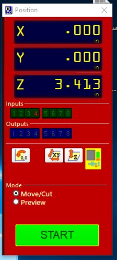
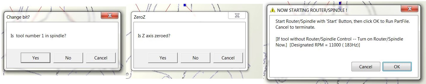
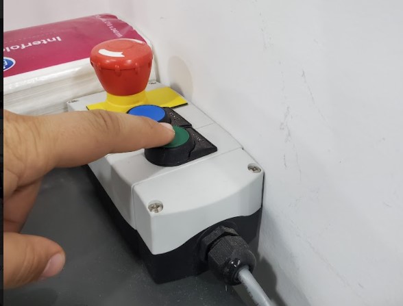
you can use Position software to make Preview to check your toolpath or Move/Cut to begin actual machine cutting . Select toolpaths to preview or cut by clicking on "Cut Part." The machine will ask about tool number, zero for Z- axis and to start the spindle "by click on green push bottom" before it can begin cutting. after pressing "Ok," the machine will begin operating according to the toolpath you set. Start the dust extractor if you haven't done it already.
The mouse pointer cannot be moved away from the "Stop" button once the machine has started working. This is an added layer of protection. The space bar on the keyboard or the machine's emergency button can also be used to halt it.
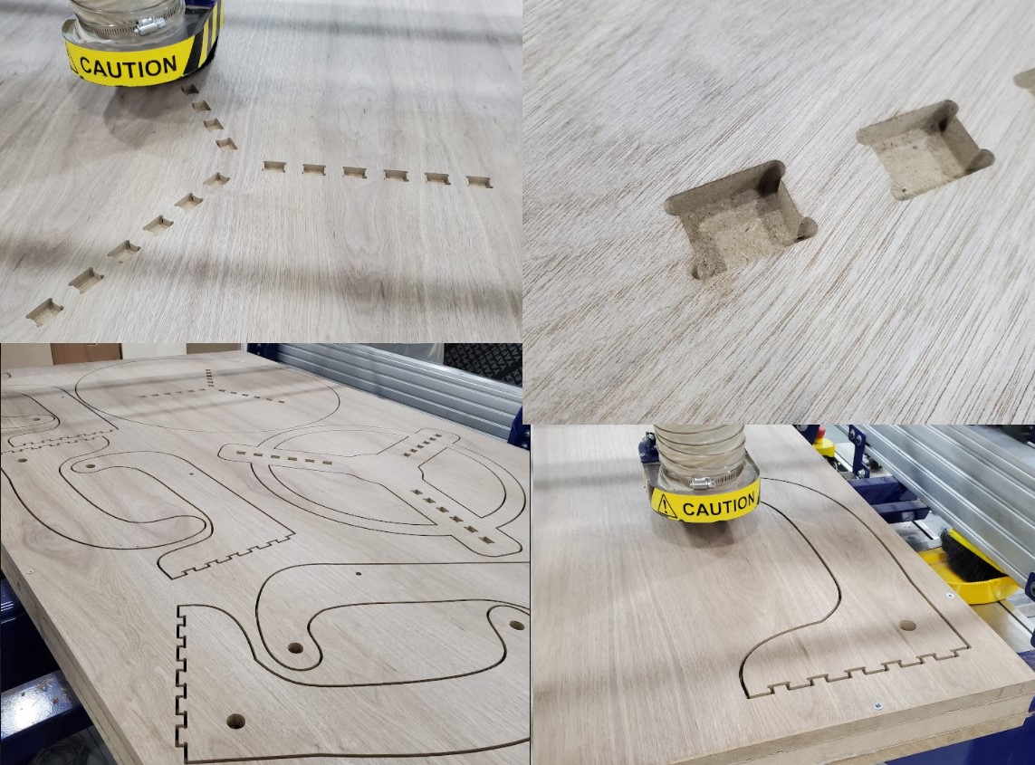
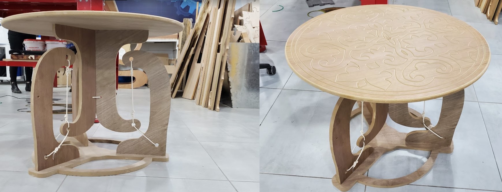
Finally, flip the table over and align the faces using a wooden pin in the middle hole. Then, on the space created by cutting the item, secure it with screws and a washers. Now start engraving on the table's face. When you're finished, secure it from the inside with a large screw and place little pieces of wood between the part and the board, then remove the screws on the ends. now Start filleting the outside edge, which is the last job.
2.3. Assembly
The best way to Assembl the table is to link the upper legs to the top and the lower legs to the bottom before tying the ropes. The pocket's dimensions are ideal for fitting the without the need for screws. I had to rubber hammer the pieces a little, but everything turned out OK. The wood we used wasn't great, and pieces were easily broken, especially sideways, but luckily my table is sturdy.
2.4. Hero shoot !


