Final Project
Electronics Design
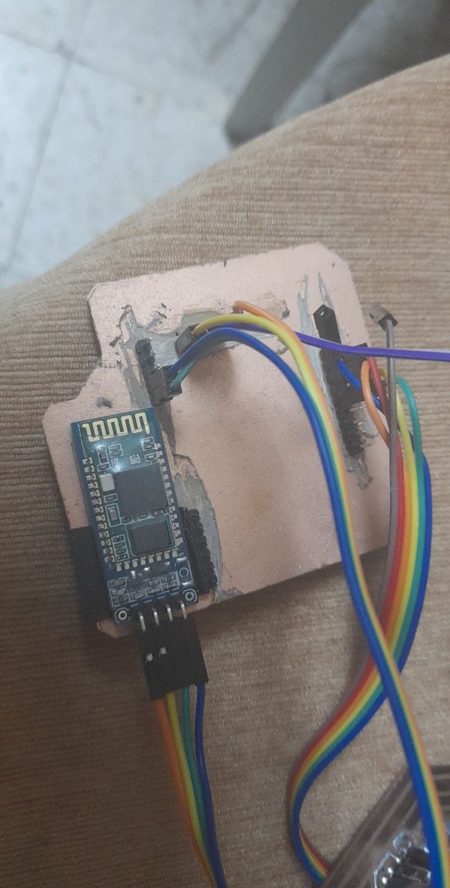
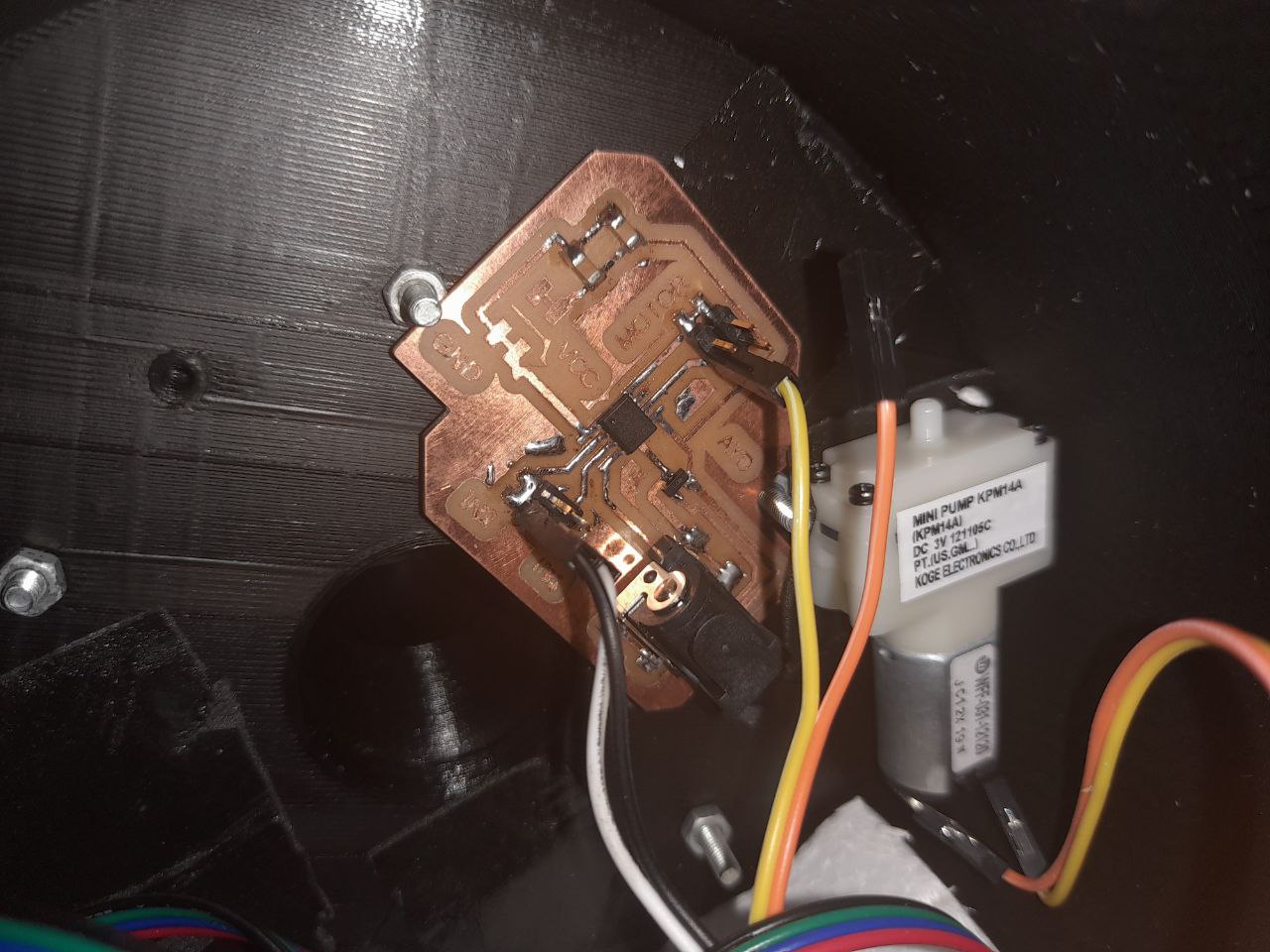
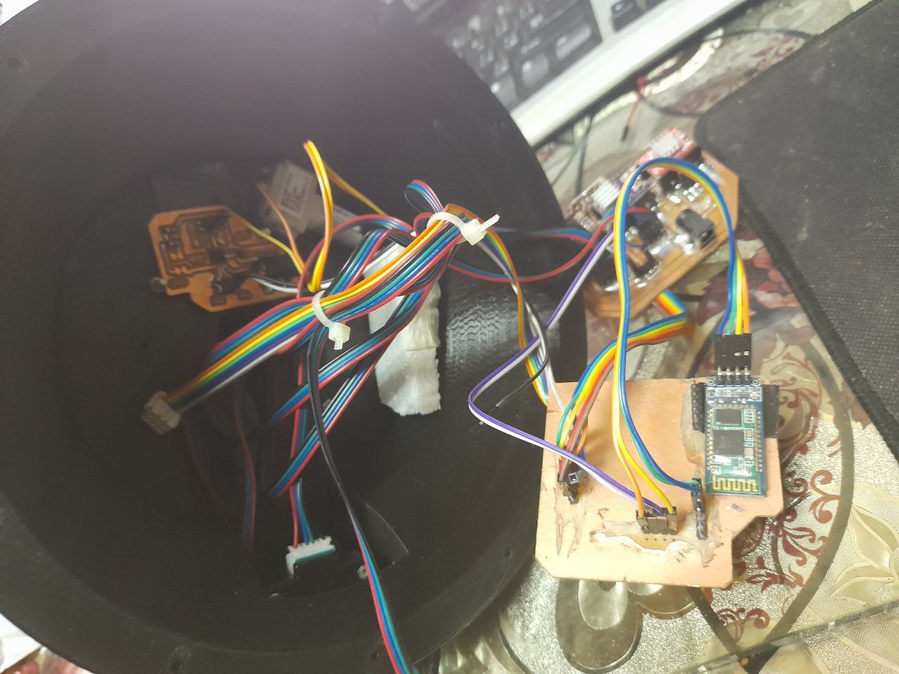
to control this arm I have designed 3 separate boards. The first one has the controller and GPIO's to control the motor drivers in addition to the bump and the valve, this board also has a connection with the Bluetooth which will receive the commands from the smartphone. the second board has sockets for the stepper drivers and 12V power to control the NEMA17 stepper motors. the third and last one has a DC motor driver to control the valve and the pump.
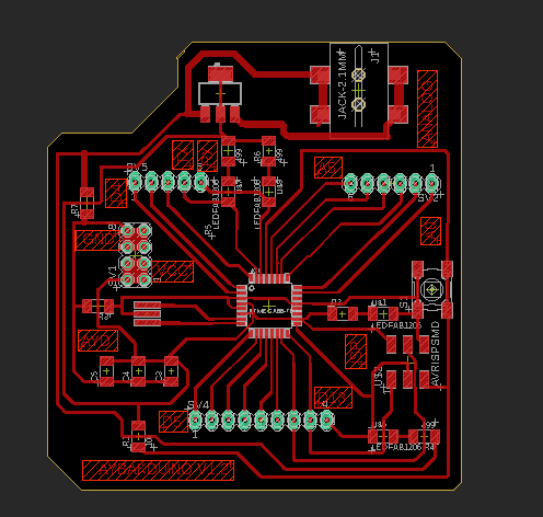
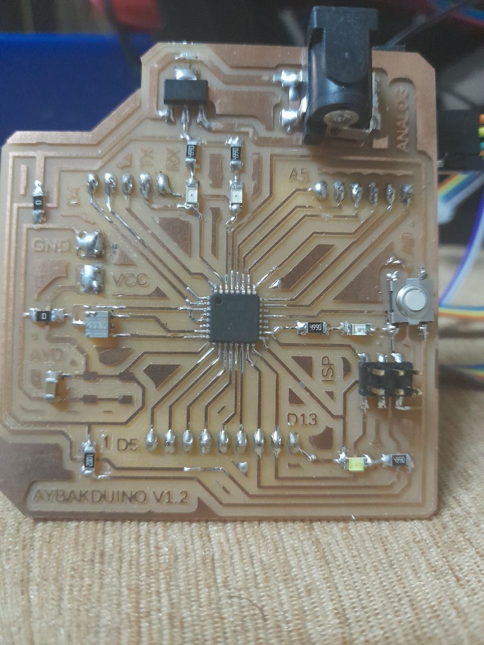
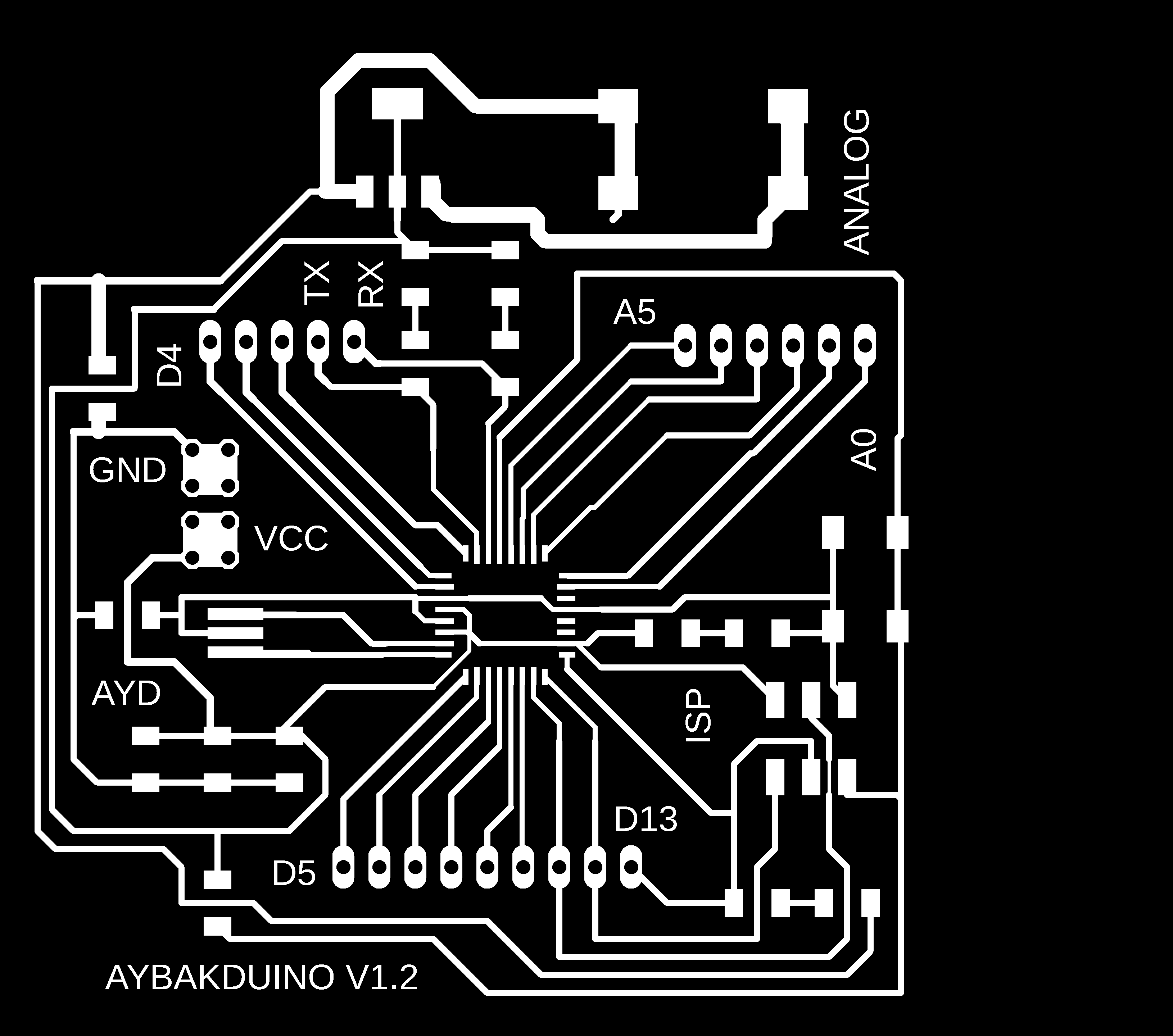
so let's start with the main control board I used ATMEGA328p as a microcontroller with 20MHz crystal .
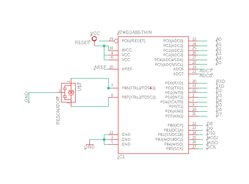
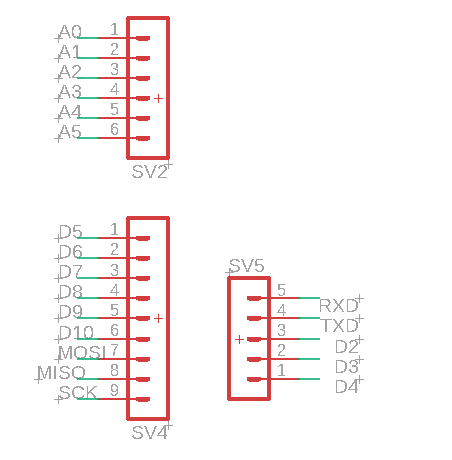
here is the pinout for the analog and digital pins including serial connection pins to connect the control board with the Bluetooth module .
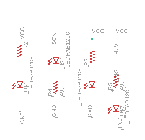
I used also 4 LEDs as indicators (TX, RX, D13, power ).
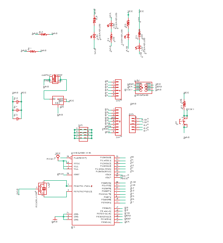
here is the schematic for the controller board .
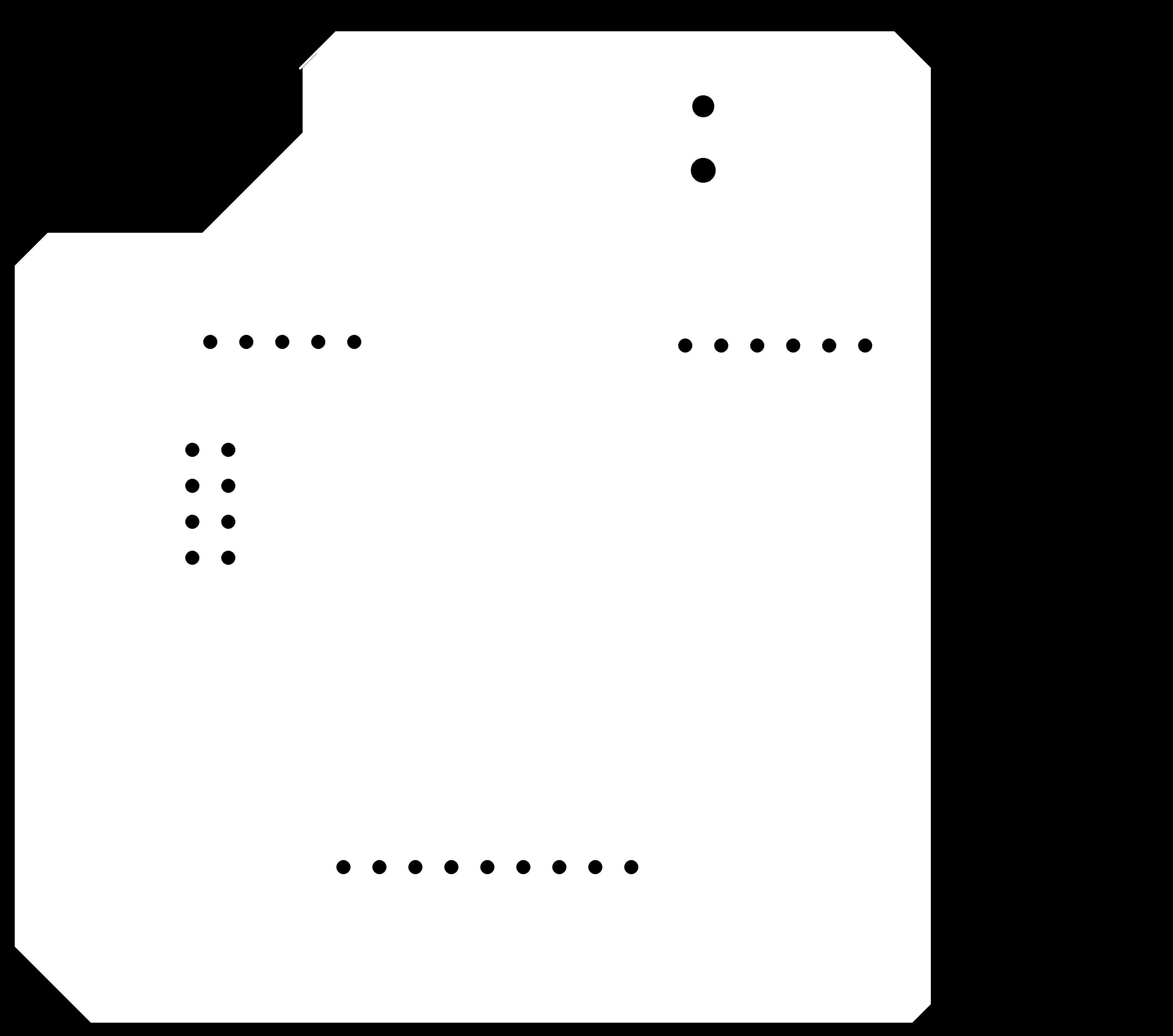
here is the layout (board) for the controller board .
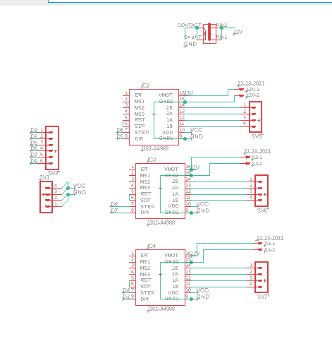
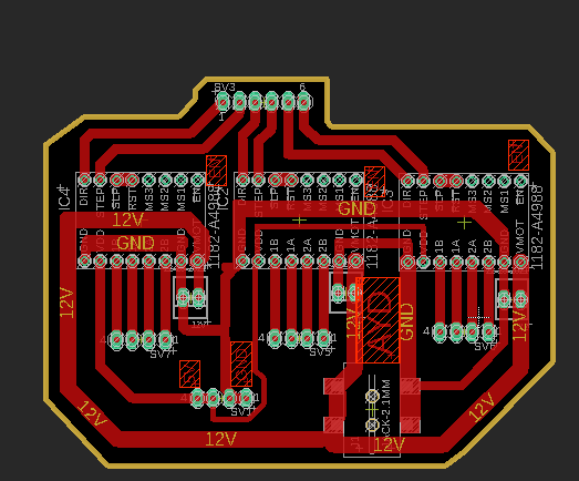
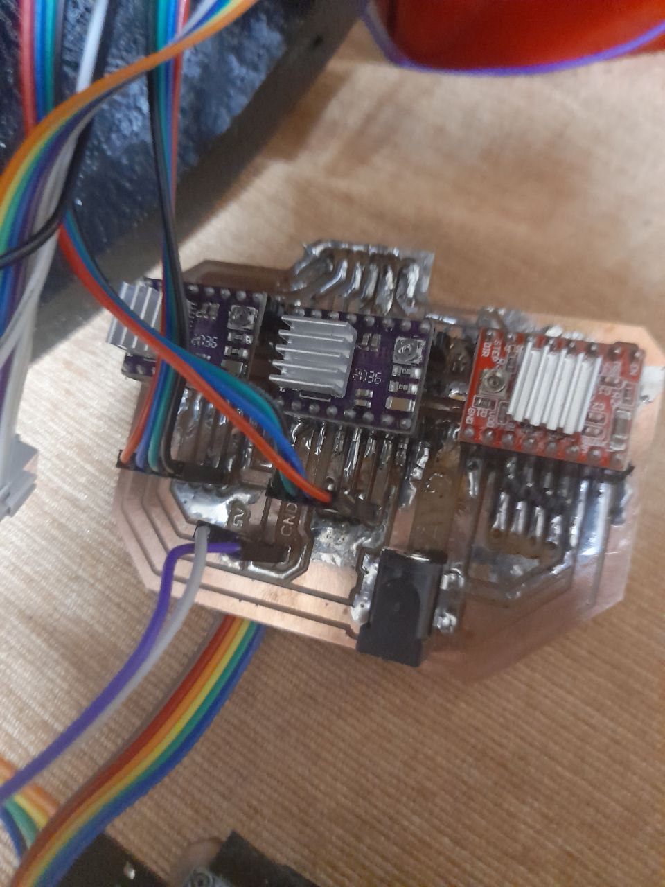
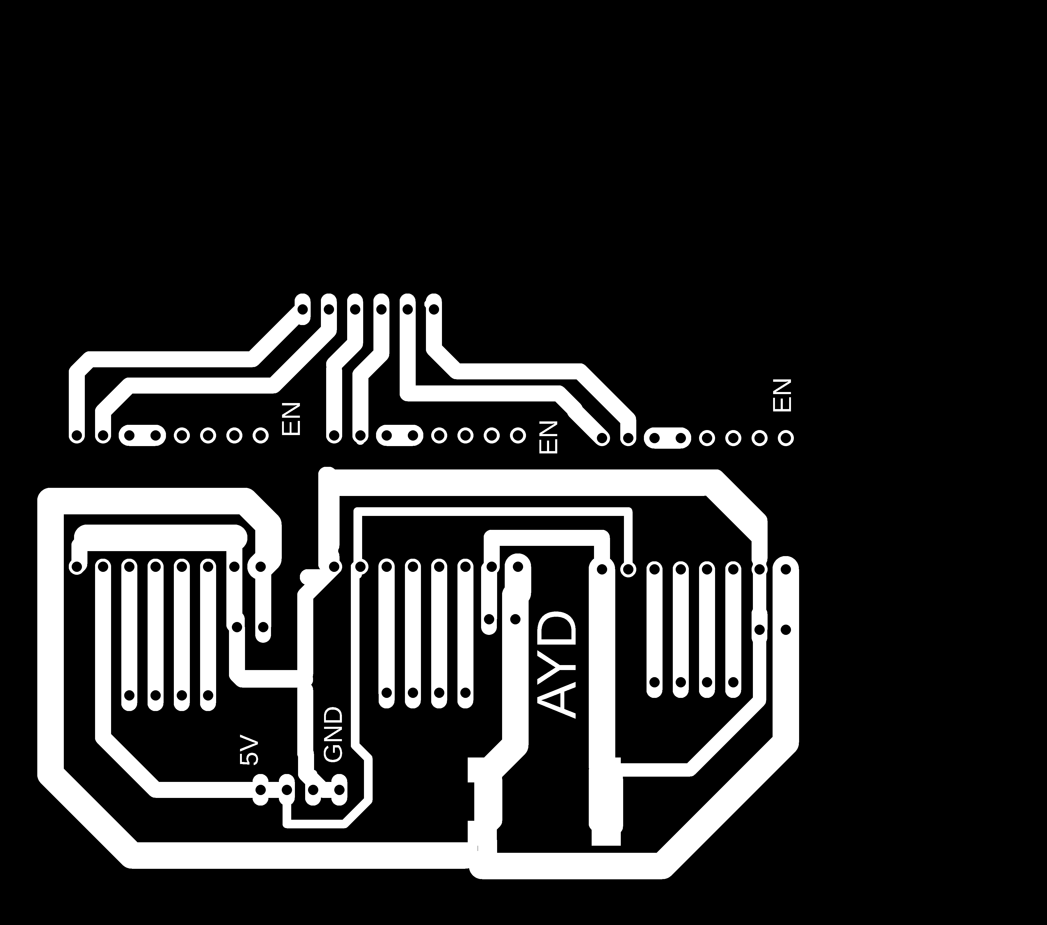
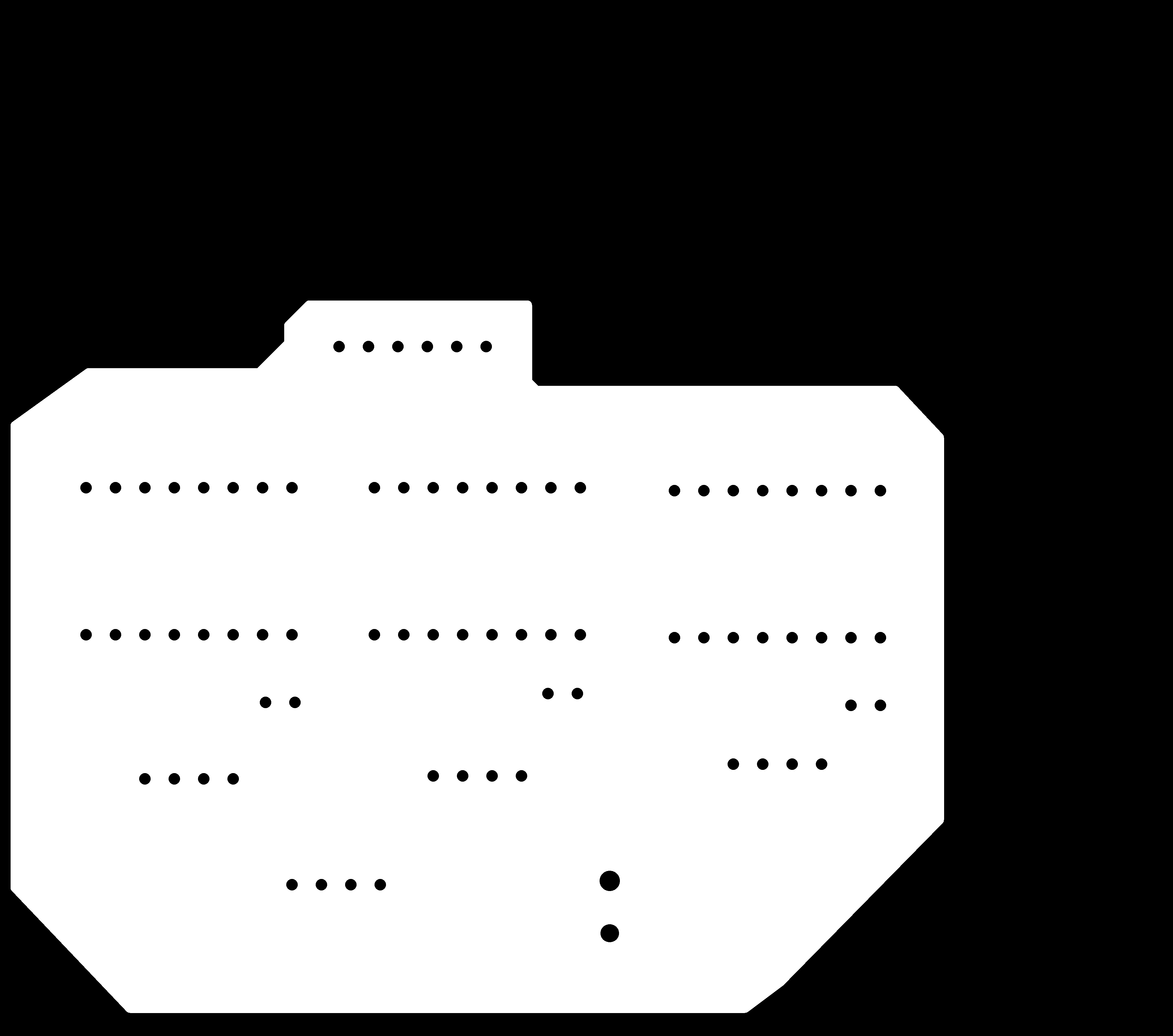
this board has stepper motor drivers sockets and 12V power supply jack
you will notice that the traces in this board is too thick and that because these traces has to deal with a large amount of current (2A - 3.5 A).
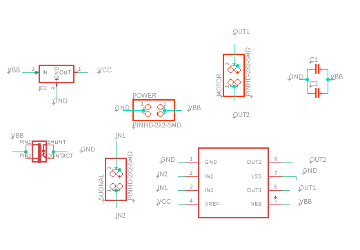
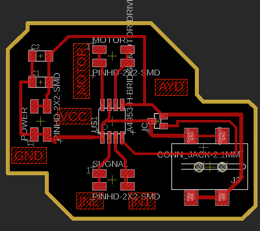
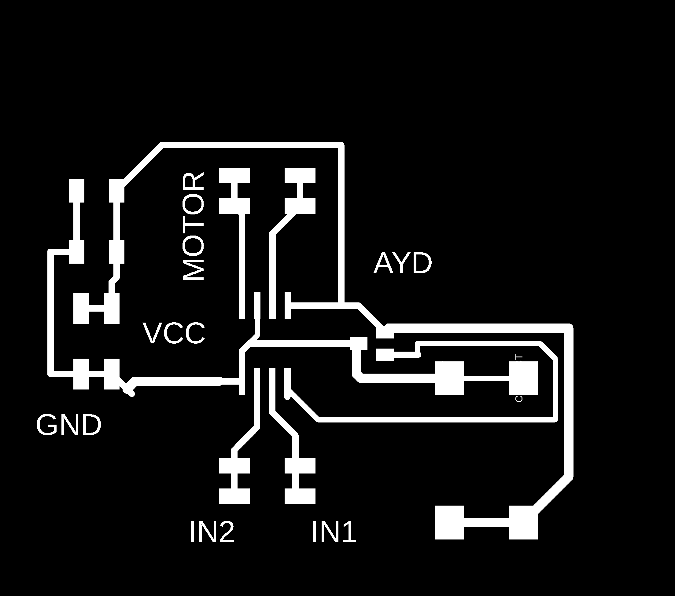
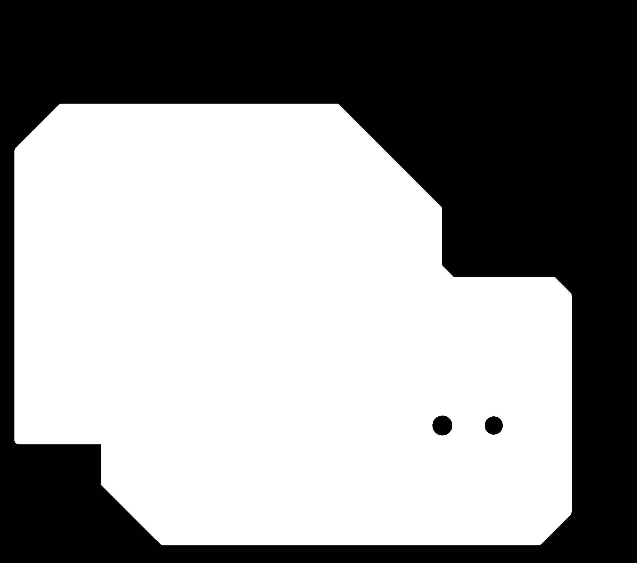
and the last board is the DC motor driver which consists of a 5V voltage regulator and the Bridge and 12V power jack
Files to Download
Eagle files
- Controller Board
- Controller schematic
- stepper driver Board
- stepper driver schematic
- DC driver Board
- DC driver schematic
PNG files
- Controller traces
- Controller outline
- stepper driver traces
- stepper driver outline
- DC driver traces
- DC driver outline