(Input & Output) Devices
1. MYO (electromyography) and MyoWare sensor
For the final project the input device was a Myoware Muscle Sensor. I had to study the sensor's datasheet in order to understand how it worked. Electromyography is a technique for measuring muscle activity using electric potential (EMG). I could also move servo motors that controlled the fingers of my prosthetic arm using electromyography.
Three elecrodes on the myoware sensor should be attached to the muscle group selected. Two electrodes should be attached in the muscle's midsection, and the third electrode should be connected at the muscle's end. The reference electrode is the one that is linked to the muscle's end. I had to clean the region with Isopropyl Alcohol before applying the sensor to the muscle. The readings will be skewed or non-existent if the sensor is not set appropriately. As a result, the sensor's positioning on the muscle is critical.


After gaining a thorough grasp of the sensor's operation, it was time to wire it up and program it. The sensor's wiring was inspired by the example below.
Wire Connection
The sensor operates between 3 and 5 volts, so you'll need a GND and VCC connection. Connection of analog pins This sensor functions as an analog Pin PMW pin, which is similar to how a potentiometer works.

It was planned to use three muscle sensors, each sensor responsible for a specific movement and to use the overlap between them for other movements, but for time constraints, only one sensor was installed responsible for closing the hand
For more information about muscle sensors go to Input Week
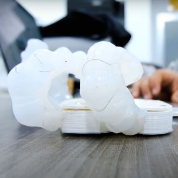
Output (Servo Motor)
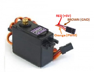
An Overview of Servo Motors
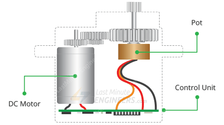
A servomotor is a rotary or linear actuator that can regulate angular or linear position, velocity, and acceleration with precision. [1] It is made comprised of an appropriate motor and a position feedback sensor. It also necessitates a complex controller, which is frequently a separate module created exclusively for servomotors. Although the word servomotor is typically used to refer to a motor appropriate for use in a closed-loop control system, it is not a specific type of motor. Servomotors are utilized in robotics, CNC machines, and automated manufacturing, among other uses.
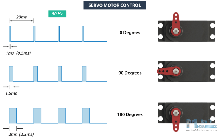
How does servo motor works:
Servos are controlled by transmitting a variable-width electrical pulse across the control line, often known as pulse width modulation (PWM). There are three types of pulses: minimum, maximal, and repetition rate. A servo motor can only rotate 90 degrees in either direction for a total of 180 degrees.Source
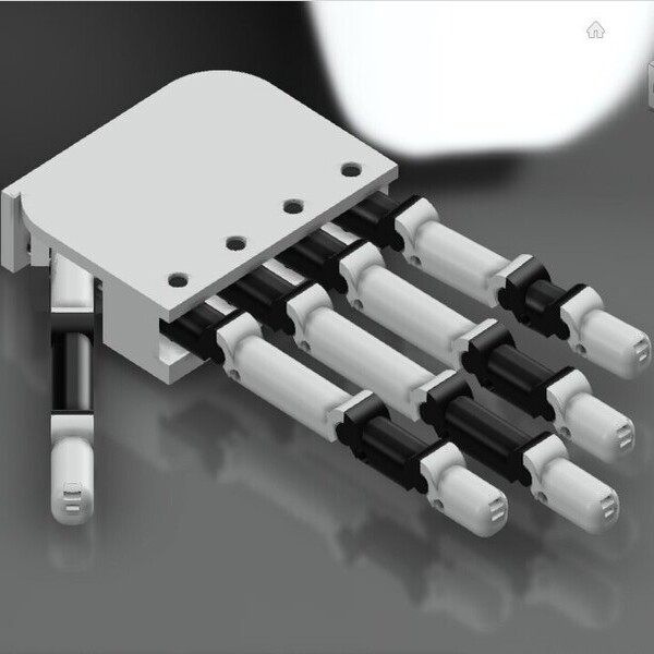
Twelve servo motors have been used, the micro servo for the upper joints because it does not require a great force on them, and the servo for the last joint, which has the greatest force when holding. Also, a servo was used to control the angles between the fingers, and two micro servos were used, in addition to a servo to control the thumbs.
For more information Input Week
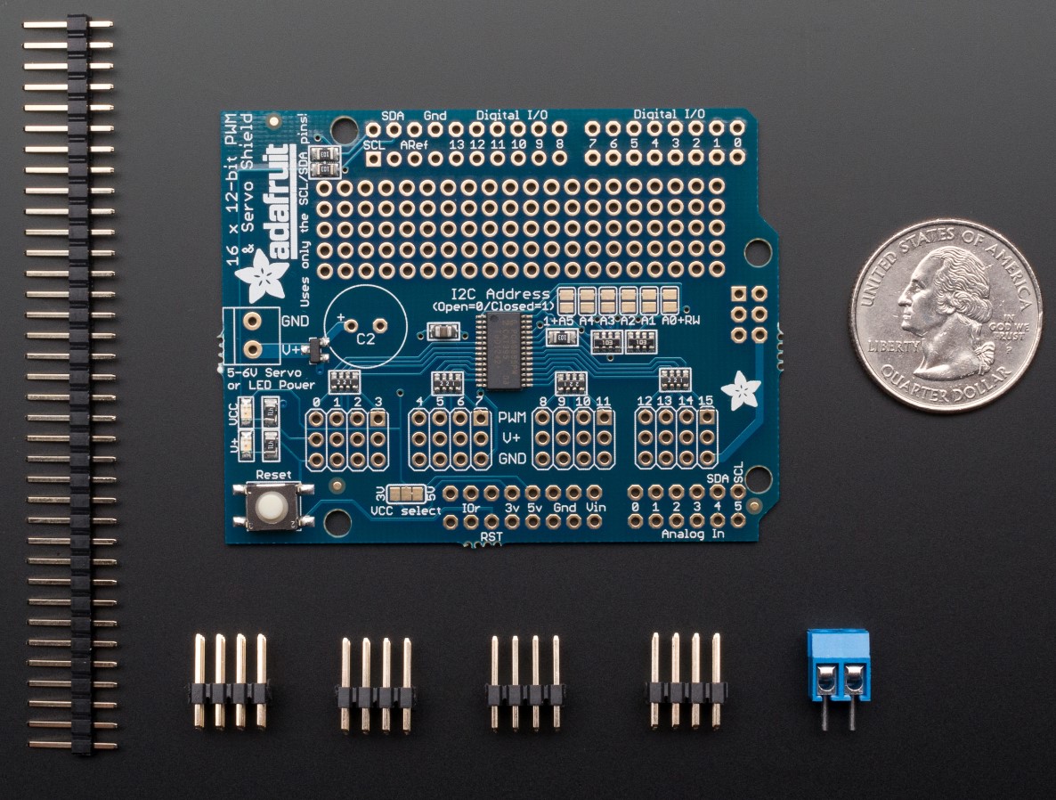
Adafruit 16-Channel 12-bit PWM/Servo Shield
The Arduino Servo library makes it simple to drive servo motors, but each one uses a valuable pin and uses some of the processor power of the Arduino. Up to 16 servos can be driven over I2C with just 2 pins with the Adafruit 16-Channel 12-bit PWM/Servo Driver Shield. All 16 channels will be driven simultaneously by the on-board PWM controller without the need for further Arduino processing. Additionally, with just 2 pins, you can stack up to 62 of them to control even more servos!
Any project requiring a number of servos can benefit greatly from the Adafruit PWM/Servo Driver!
For more information Adafruit website
Datasheet
Wire Connection
In this section, we will assemble the board with the shield , the sensor and finally the servo motors. In the beginning,Put the shield on the arduino then connect all servo motors to servo motors pins on the shield. The shield works on IC pins, so the rest of the pins can be used normally, except to IC pins ( A4 , A5 , SDA, and SCL).