13. Embedded Networking and Communications
This week we learned about creating a network. Unfortunately, once again. This is something I have zero experience in. Luckily, I have some help.
Reduce, Reuse, Recycle
I have a board that I’ve been working with for most of the projects. It’s worked out fairly well for me, but it doesn’t have any way to network with something else.
After talking with Garrett, with a few tweaks, I can shuffle my components around and add the connectors for I2C.
Networking: Not Just for LinkedIn
I’ve heard I2C mentioned multiple times throughout the course, but never really understood what it was referencing.
ATTiny412 Chip
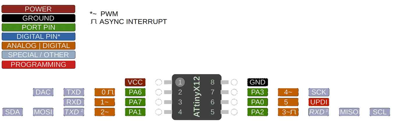
In order to use I2C, there are certain pins on an ATTiny412 that need to be used. In this case, they are the bottom two pins, or pins 4 and 5.
Pin 5 is called SCL, which stands for the clock, and pin 4 is for SDA, or sending data. Something to note, when connecting these pins to another board, the wires have to go from SDA to SDA and SCL to SCL.
As I have my board right now, one of those pins is being used for my Neopixel. I need to move it to a different pin so I can add the networking. I also want to change the pin style so they’re not sticking straight up, but instead connect from the sides. This will be more in line with how my boards will be in my final project. I also need to add a pull up resistor to each side.
All in all, not too bad of an adjustment to make. I can do this. I got this.
Same Board, New Version
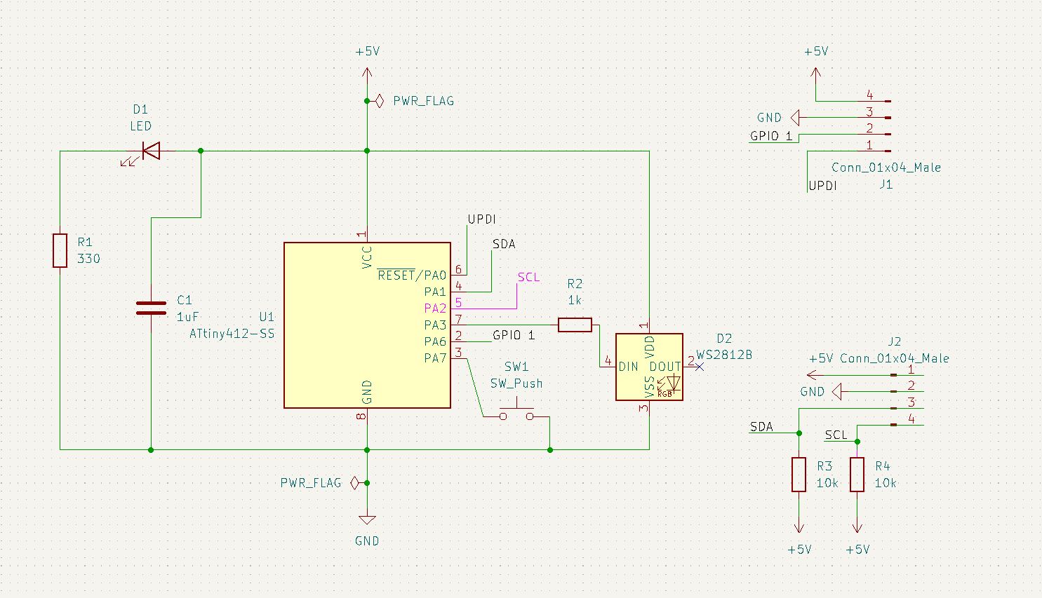
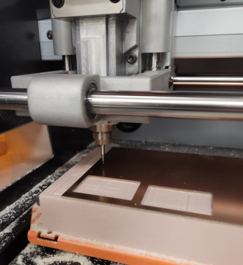
I won’t go into details here about making the board; check Electronics Production and Electronics Design weeks for more information. I used the files from my second board and made adjustments/added components to make this newest version.
I used Garrett’s board as a template of sorts for what I needed for my own.
I had to make a few changes throughout the process, switch some pins around, and eventually add a 0k resistor as a jumper to reach the 5v around the whole board.
The traces game was frustrating as usual, but then I had issues with the background. Instead of filling in the space, it stayed as an outline. While this didn’t affect the overall process too much, it was a bit frustrating. I asked Garrett and David about it, but neither of them could figure out why it didn’t work.
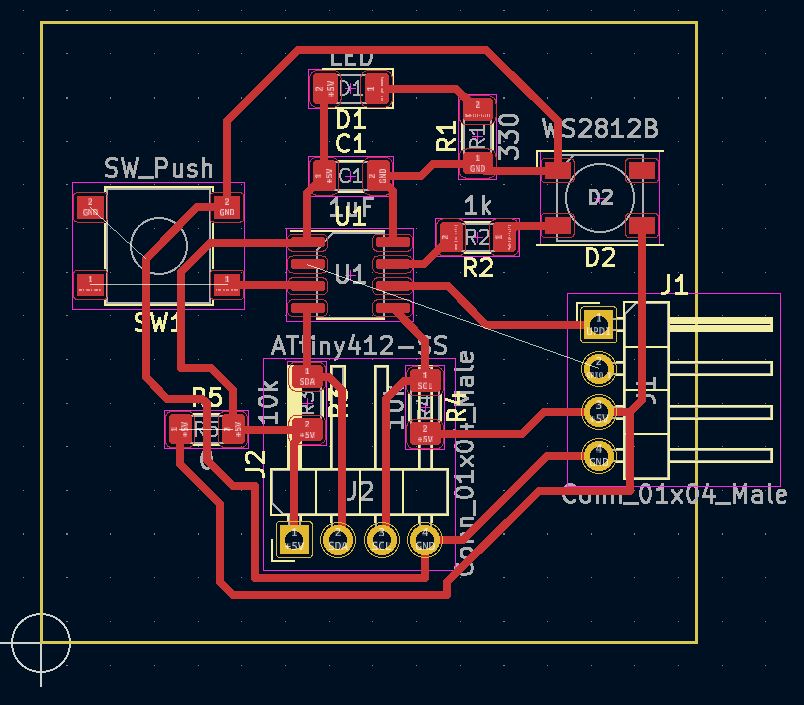
The next fun part was remembering how to take the KiCad and convert it into something usable. But after some false starts, I got the files ready to go and went to mill my board.
The information on this board is found on Week 8, Embedded Programming, since I ended up using this board to work on some older weeks.
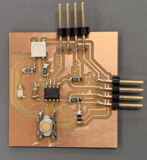
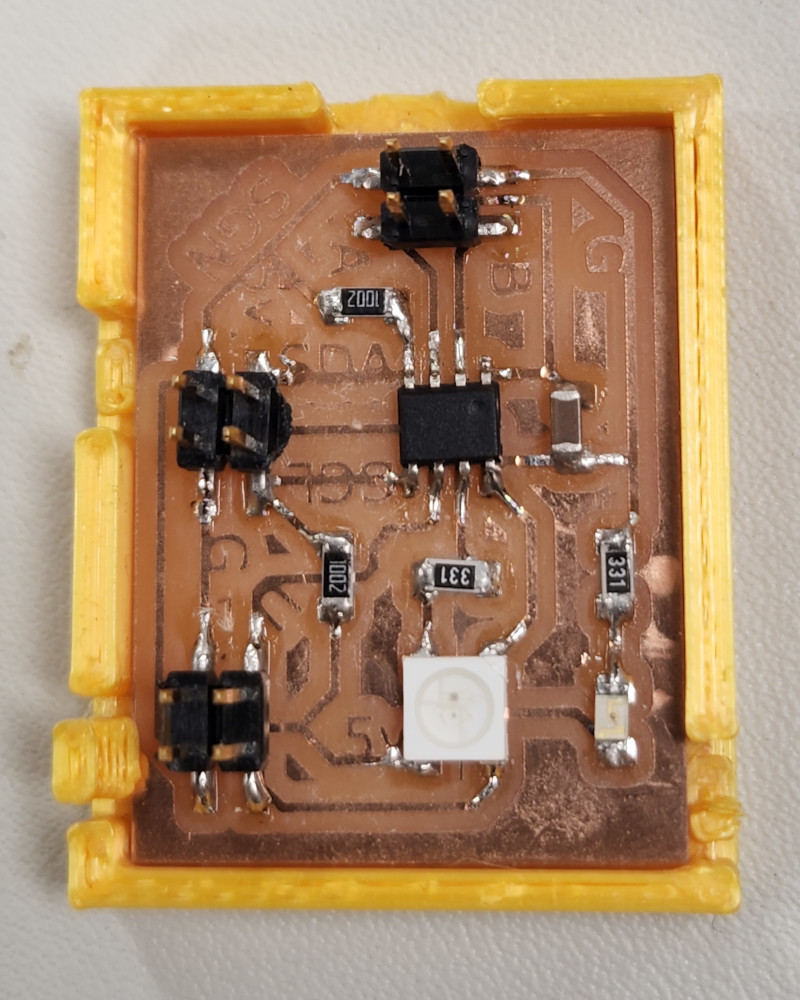
I’m really proud of the fact that I got the whole thing into a square. Progress!
After milling and soldering the board, I plugged it in with my programmer to check that I did everything correctly. The LED power light came on, always a relief, and I tried the following program to check the NeoPixel:
Pixel_Blink Code
// https://github.com/adafruit/Adafruit_NeoPixel/blob/master/examples/strandtest/strandtest.ino
// and
// https://create.arduino.cc/projecthub/robocircuits/neopixel-tutorial-1ccfb9
// NeoPixel Ring simple sketch (c) 2013 Shae Erisson
// Released under the GPLv3 license to match the rest of the
// Adafruit NeoPixel library

#include <tinyNeoPixel.h>
// NeoPixel Ring simple sketch (c) 2013 Shae Erisson
// Released under the GPLv3 license to match the rest of the
// Adafruit NeoPixel library

// Which pin on the Arduino is connected to the NeoPixels?
#define PIN        4 // Garrett Attiny Neopixel Board

// How many NeoPixels are attached to the Arduino?
#define NUMPIXELS 1 // only 1 on og board

// When setting up the NeoPixel library, we tell it how many pixels,
// and which pin to use to send signals. Note that for older NeoPixel
// strips you might need to change the third parameter -- see the
// strandtest example for more information on possible values.
tinyNeoPixel pixels(NUMPIXELS, PIN, NEO_GRB + NEO_KHZ800);

#define DELAYVAL 500 // Time (in milliseconds) to pause between pixels

void setup() {

  pixels.begin(); // INITIALIZE NeoPixel strip object (REQUIRED)
  pixels.setBrightness(85); // about 1/3 brightness
}

void loop() {
  pixels.clear(); // Set all pixel colors to 'off'
  delay(DELAYVAL);
  // pixels.Color() takes RGB values, from 0,0,0 up to 255,255,255
  // Here we're using a moderately bright green color:
  pixels.setPixelColor(0, pixels.Color(0, 150, 0));
  pixels.show();   // Send the updated pixel colors to the hardware.
  delay(DELAYVAL); // Pause before next pass through loop
  pixels.clear();
  delay(DELAYVAL);
  pixels.setPixelColor(0, pixels.Color(150, 0, 0));  //red
  pixels.show();
  delay(DELAYVAL);
  pixels.clear();
  delay(DELAYVAL);
  pixels.setPixelColor(0, pixels.Color(0, 0, 150));  //blue
  pixels.show();
  delay(DELAYVAL);


}
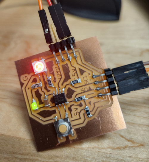
IT WORKED!!! I don’t think you understand how excited I am to be able to program such a simple thing.
Networking For Realz
Now that I had a working board, it was time to try out the networking portion. When I made the board, I made sure to label the header pins, and it made this next part much easier. I highly recommend everyone do this when they make their own boards, but anyway.
Garrett had his boards programmed and ready to network, so we decided to use my board as the master and network to one of his, again as a test.
I used the following code, also found on Garrett’s site:
#include <Wire.h>

byte led_state;                      // a variable, storing the led "on" or "off"

void setup() {
  Wire.begin();                       // initialize i2c system
}

void loop() {
  led_state = 1;                  // value of "1" will be set.
  sendDataWire();                 // call the function to send the data ("1") over I2C
  delay(500);                     // wait half a second
  led_state = 0;                  // change value of data to "0"
  sendDataWire();                 // fall the function to send data.
  delay(500);
}

void sendDataWire() {              // This is where it actually uses the i2c system to send data
  Wire.beginTransmission(0x54);    // prepare transmission to slave with address 0x54
  Wire.write(led_state);           // Write the received data to the bus buffer
  //Wire.write("\r\n");               // add new line and carriage return for the Serial monitor
  Wire.endTransmission();           // finish transmission
}

Aw yeah, a network!! Look at it go!
There are a couple things to note in this code. First of all, the library for I2C is called “Wire.h”, referenced at the beginning of the code. The library is found here, once again thanks to Spence Konde and MX682X. There is also a lot of great information about I2C in general.
The second thing we had to tweak was the address. Since Garrett had multiple boards, they each had their own address, so it was a matter of trial and error to find which address went with the board we had hooked up. In this case, the address was “0x54”, which is a hexadecimal address.
This was a quick and dirty way to network, but for me, I’m glad it was rather simple and easy to understand.
Files
Here are the files for the networking board. The program I used to make it the master in the network is found here.
Group Project
The link to the group project is found here.
As mentioned above, I used my board as the master and networked to Garrett’s secondary board. I’m really happy that it worked, not matter how simple!