15. Wildcard Week - 5 Axis Machining
I’m so glad that 5 axis machining is on this list. That makes this week much easier to handle and figure out what to do.
The Machine
I program, set up, and operate a DMU 75 monoBlock 5 axis by DMG Mori. I’ve been using her since she was installed just over a year and change ago. The part that I’m going to highlight here was one that we used to have to send out to a vendor, but now I’m able to program and run this part in house.
I’m not able to show too much of this part because it is an actual piece used in our machines, but I’ll give as much information as I can.
Designing and Programming the Part
This is an existing part, but in order to make it machinable, I had to make some modifications to it. At the start of the operations, I removed certain features that weren’t necessary for that part of the process, and added them back in later. Often when trying to program, details can be more of a hinderance than a help, especially in the beginning when the goal is simply to get the shape and size correct.
I’ve run many different star wheels in the past, and have access to all the programs for them. This makes it easy to program a new part that may have features from many different wheels; I can pick and choose which toolpaths work. If I have trouble or am not sure how to machine a feature, I have a reference to check.
The only thing I have to consider before running this is how long it will take. Usually a part this size will take me all day to do. I have to consider what other parts are due, how often I have to change the setup, and if I have to remove or add a vise, what other parts could I do at the same time to minimize workhold shifting.
Design
With all those things in mind, it’s time to design. I use a special kind of model called manufacturing models. These do not change the original base model itself, but instead allow me to remove features in order to create optimal toolpaths for that particular operation.
I can also add features if I need to. For example, if I had to hold a part down with bolts or toe clamps, I could add features in those locations and create a toolpath the cuts around them. I could also add features to improve surface finishes and support delicate features. I had another part that had a long, thin feature that tapered at the end, so I couldn’t hold onto it with the vise jaws. Since it was unsupported, it would have vibrated, or chattered, if I had tried to machine it. Instead, I added material to this section so it wouldn’t be machined during the operation, then created a fixture to hold it and finished the part. It took a couple extra steps, but I got a finished part that would pass inspection the first time instead of a bunch of scrap parts.
Programming
I use Fusion 360 to program my parts. We also have access to Esprit, but I haven’t been trained on it yet. We recently hired a programmer who has over 16 years experience with it, so I hope to learn a good bit from him. Esprit is a CAM program that is designed specifically for 5x machining, but because of that, it has a very steep learning curve. For this part though, Fusion is more than capable of getting the job done.
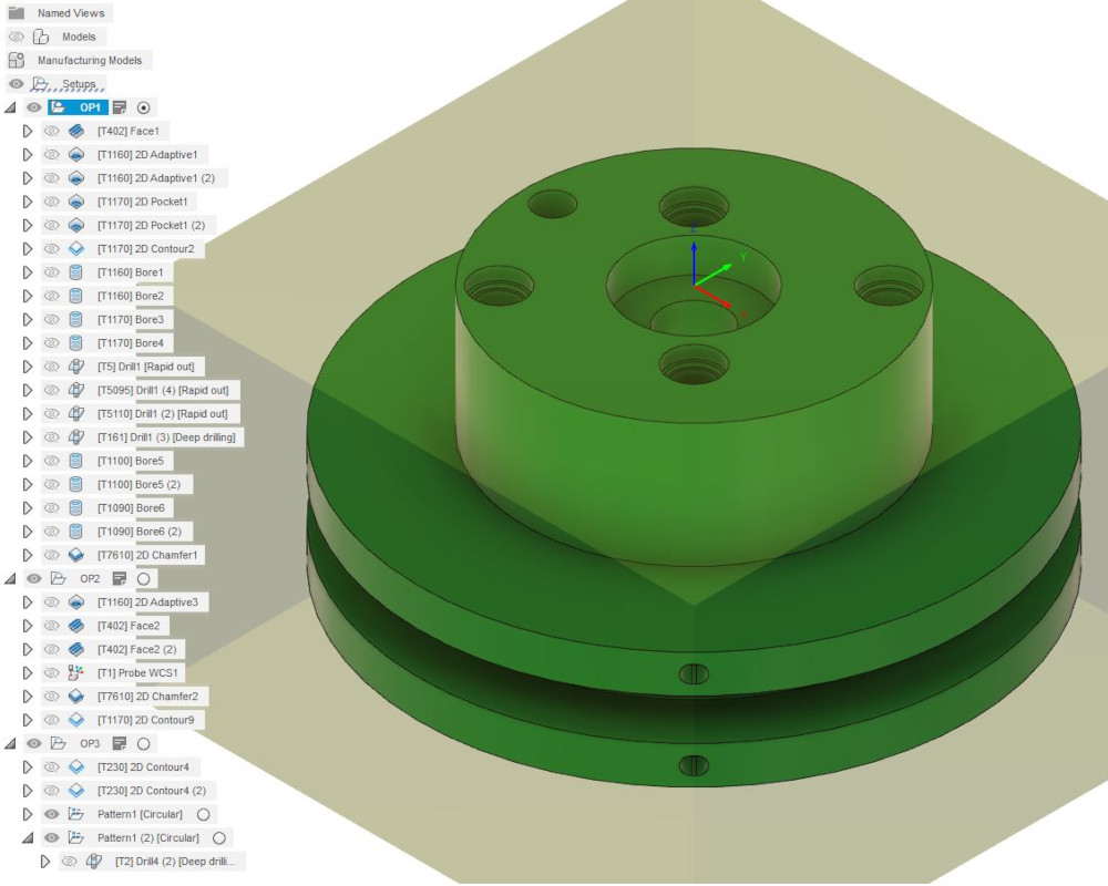
The first operation will create the blank I need to put in the fixture later down the line. This will machine the profile of the part, the step, or boss, and the holes on top. Then I’ll flip the part for the second operation.
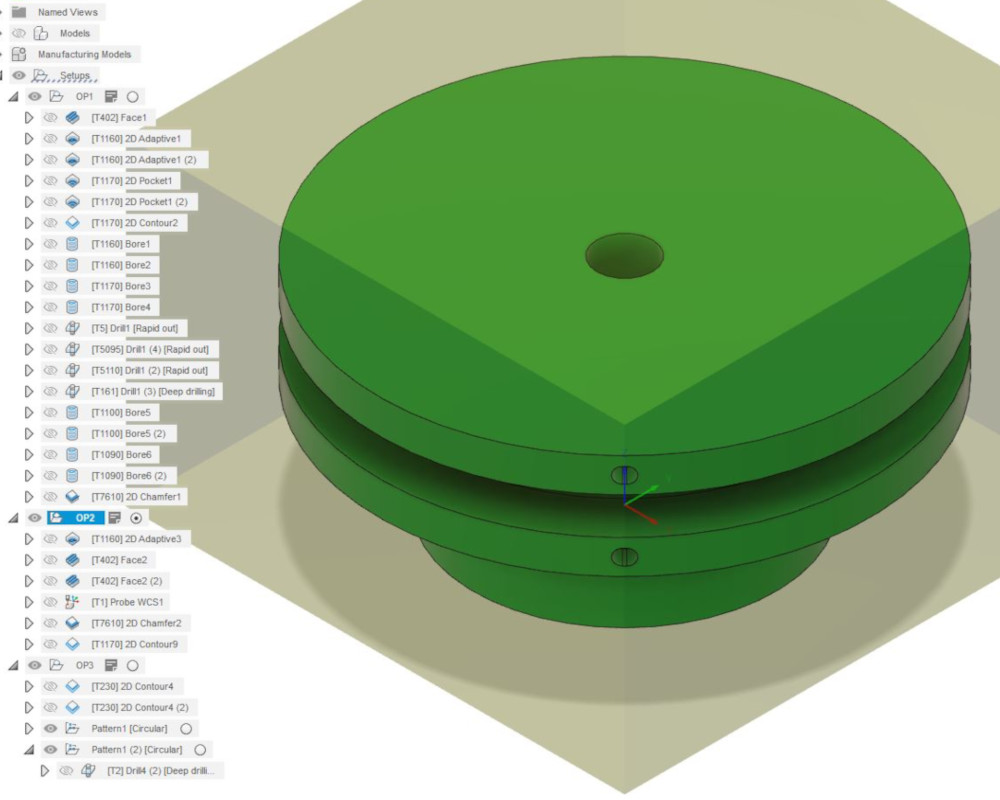
Operation 2 will remove the excess material on top and bring the blank to the final thickness.
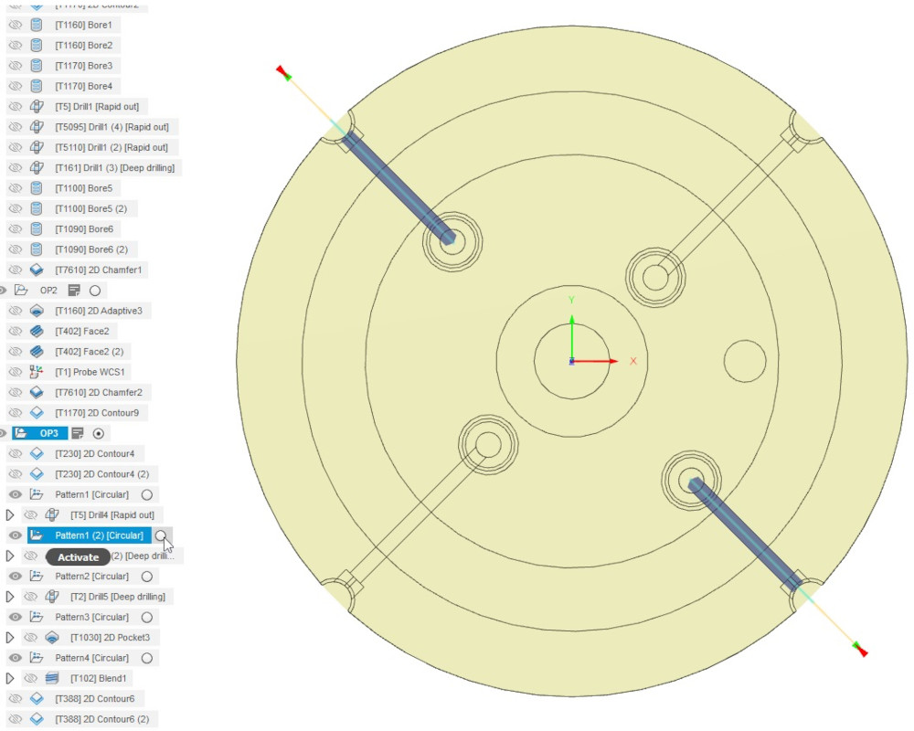
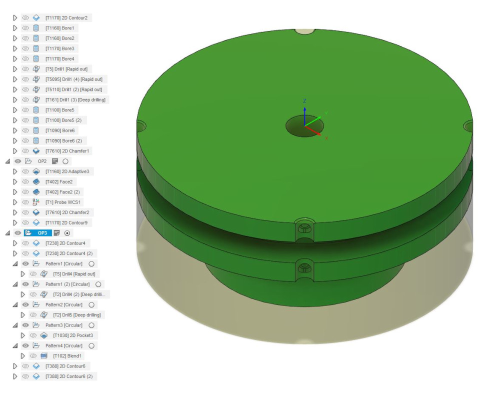
The last operation is to add all the remaining features. This requires a fixture that is then clamped into the workholding so the part can be rotated. Up to this point, the part could have been done with a 3x machine, but the internal features are on certain angles that need to line up exactly with the holes created in OP1.
Last step is with the fixture, but the fixture needs to be prepared first. The part has a locating pin that needs to be machined on the fixture, then the wheel is held in place in the correct orientation so all the vacuum holes line up properly. Each wheel is slightly different, so the fixture needs prepared for each one every time. If the fixture is ever removed for any reason, the hole needs to be put in again. This time, I had a fixture with flats so it could be removed and put back without having to locate again.
Since it’s a simple operation, I programmed this at the controller with the conversation inputs. Once the fixture is prepared, I put the wheel on and did the final operation, which is all the actual 5x toolpaths. Or more like 3+2 since it rotates the table then does the cut/drilling.
5x or 3+2?
What’s the difference between the two?
When people talk about 5 axis machining, most people think of the fancy machining with the table moving at the same time as the spindle. This is simultaneous machining. This is the most entertaining machining to watch (personally I love watching the part dance around), but it is also the most difficult to program and frankly, stressful to run.
The difficulty comes from having to account for multiple degrees of movement at the same time. This also means you have to account for more than just the tool, but also the toolholder, the spindle, and the table and how they all will interact throughout the toolpath. Just because the path starts with enough clearance does not mean it won’t get too close later.
This type of machining usually requires another program to verify the toolpath. These programs have a model of the machine, the workholding, and the part and stock that are all used together to make sure nothing crashes as it runs. Once verified, it’s important the the actual machine be set up exactly as simulated in order to run properly.
Simultaneous machining can create some amazing parts, but in most cases, this level of machining isn’t necessary to create a part.
The second and more common form of 5 axis machining is called 3+2 machining. This refers to the way the machine moves, meanining it machines with the standard 3 axis, then adds another axis as needed.
For example, an operation may include toolpaths that don’t require any movement from the table, then rotate 90 degrees in the C axis to machine the side of the part. The spindle will move out of the way, then the table rotates, then it continues machining.
While this may seem like a waste of potential (and not as much fun to watch), it allows for more accurate and efficient machining because it eliminates multiple setups. Every time the part is removed from the workholding, it allows for mistakes to be introduced, such as setting up on a chip, putting the part in incorrectly (wrong orientation or wrong side), or any other human errors.
It also cuts down on how long it takes to make a a part. Cutting down on setups eliminates the set up time, such as eliminating switching vises, adding/removing fixtures, and changing tools. It also allows for certain toolpaths to be consolidated, reducing tool change times.
The Part
The part I’m making is a star wheel, specifically a vacuum wheel. This piece is part of a large assembly that moves the bottles/vials/syringes through the machine. We have some types that simply move the bottles through mechanically, by having pockets that each bottle sits inside while the wheel rotates to the next station. Others, like the one I’m working on, use a vacuum instead. It uses a series of holes that are drilled through the part and in the pockets to pull a vacuum and hold the bottle in place while it moves instead of depending on a counter guide.
Material and Tooling
The size of the wheel can vary, and are usually made of different plastics. We use either UHMW, or ultra high molecular weight, PET, or POM (what some people refer to as Delryn). This part is made of PET.
Material Types
UHMW is usually very soft and tends to “fuzz” instead of cut cleanly. This means that instead of removing material, it remains attached to the part like stings, or a pompom. This material requires a very sharp tool in order to leave the best finish possible. POM is a harder plastic, so while a sharp tool works best with this as well, a slightly dull tool will leave a decent surface finish too. Lastly, PET is a bit of a mix of the two. It’s not as hard as POM, but doesn’t fuzz as much as UHMW. It also has a tendency to melt if it’s being cut with a tool moving too fast without coolant. For example, we have to cut this material with the band saw that has the coolant option. Our second band saw doesn’t use coolant, so the material melts in place, and it is nearly impossible to cut through the melted material.
This time, the router, or order, for the part calls for PET. I know most of the tools I have will cut this material without issue, but there are a couple I want to double check. These are the drills. One thing I need to check is tool length, since I’ll be drilling relatively deep holes, and the second are the speeds and feeds. Longer tools need slower speeds so the centrifugal force doesn’t bend them, and because this will be a small tool, there’s a chance that the material will melt if it’s not cutting fast enough and if the coolant can’t get down into the hole.
Tooling
The tools I used are specific for plastic. Most endmills have multiple flutes, but due to the nature of plastic, the best cutter to use is a single flute cutter. In addition to the endmills of various sizes, I’ll use a face mill, a spot drill, and different drills.
The tool list will be included in the setup sheet in the files below.
Setup
OP1 - The Blank
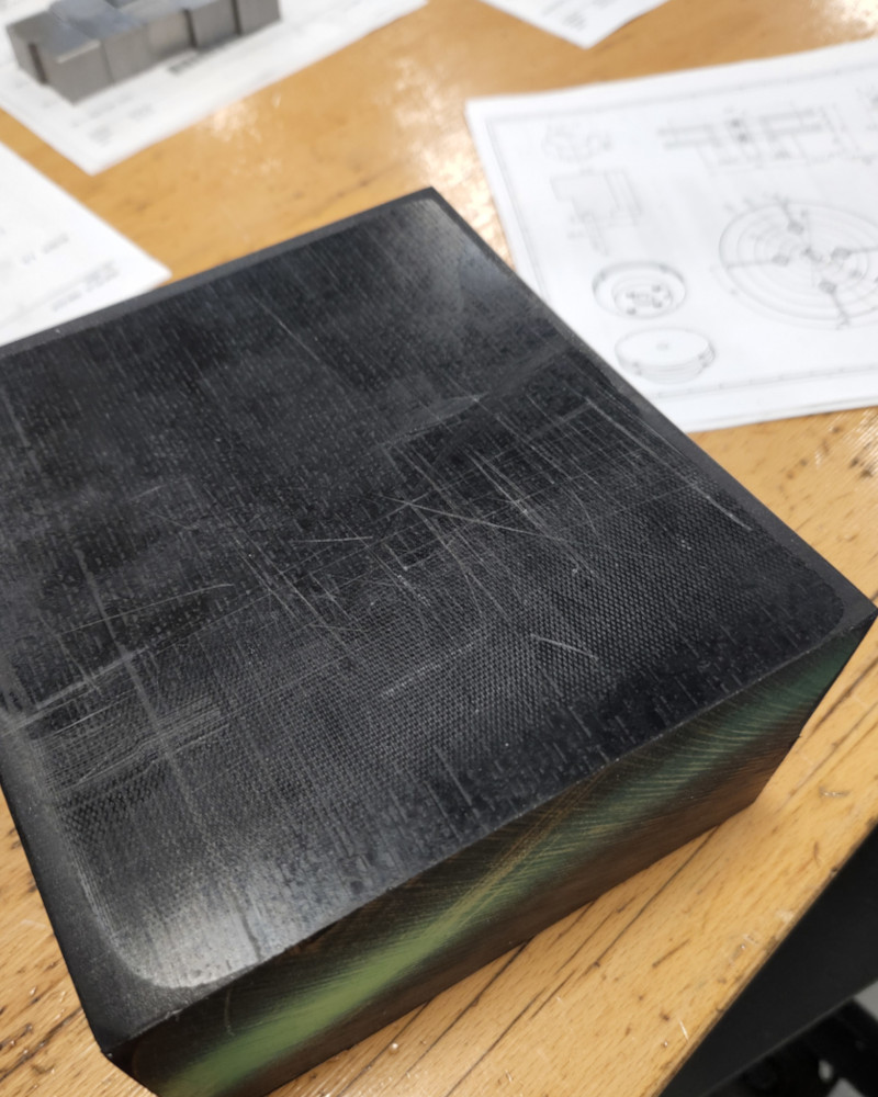
The stock size is determined by the program. I usually add a set amount to each side and extra on the bottom to hold in the vise. Unfortunately, the stock we have that is big enough has a lot of excess material, so the second operation will require a lot of material removal.
The nice thing about my vise is that it’s modular, so I can add or switch out jaws or extensions depending on the size of the part I’m working on.
For the raw stock, because it’s so wide, I needed to add the extension and remove the stepped jaws. Each operation required a slightly different setup.
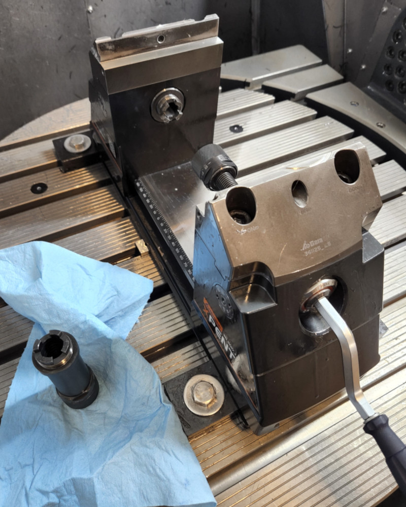
OP2 - Removing Excess Material
For the second operation, I had to remove the extension and add a 3 jaw chuck. I used the vise to hold the chuck in place, then held the part in the jaws of the chuck. I needed the 3 jaw chuck to hold onto the round portion.
For this operation, I needed to remove the excess material. First I used the adaptive toolpath to remove the excess material around the edges so it wouldn’t vibrate during the next toolpath.
Then I used the facing operation to remove all the remaining material.
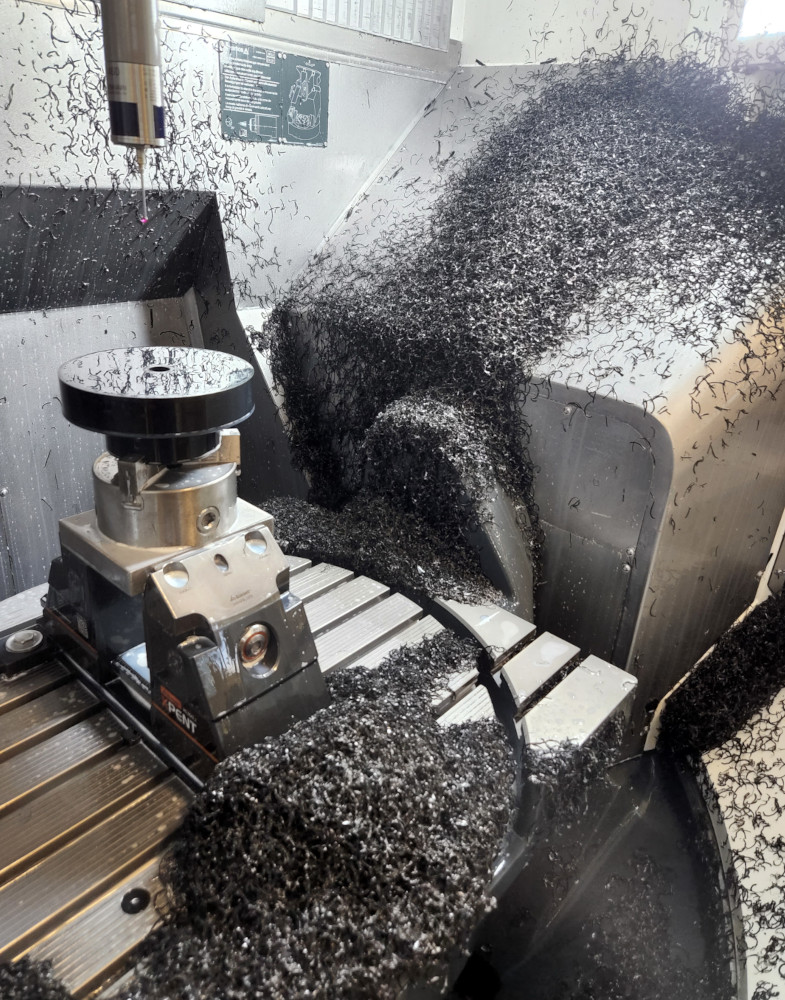
So much material…
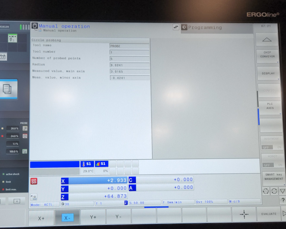
The screen to probe the center bore.
Before moving on to the next operation, I stopped and probed the part again. When I set up this operation, I had to use the raw stock to locate the part. Because this material was cut with a band saw, the sides were uneven and not parallel, so the position is usually slightly off from the machined portion.
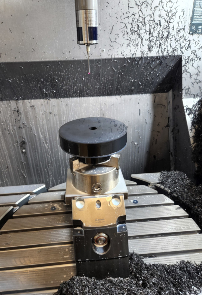
Once the excess material is out of the way, then I could probe the center bore to get the exact location. The last operation is a chamfer, so I needed to be precise so it would be even around the perimeter.
OP - Setting up Fixture
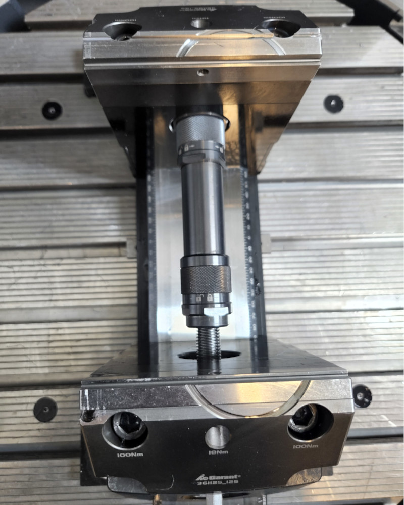
Once the operation was finished, I removed the 3 jaw chuck and put in the stepped jaws and the extension again. The fixture needed a locator pin to line up all the holes.
Instead of creating a whole program, it was easier to create a program at the controller to bore a hole in the correct location. From there, it was a matter of making minor adjustments to meet the tolerance so the pin would fit snuggly.
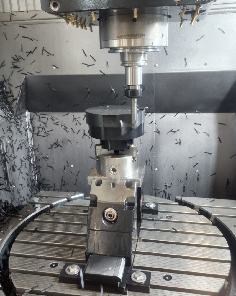
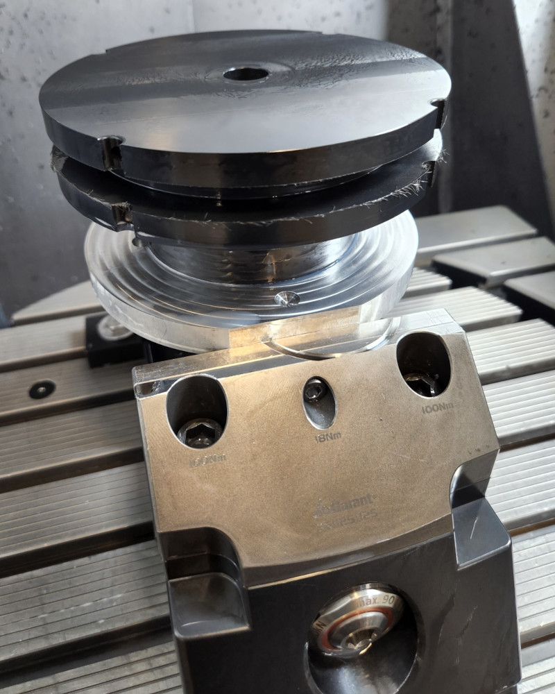
OP3 - Final Machining
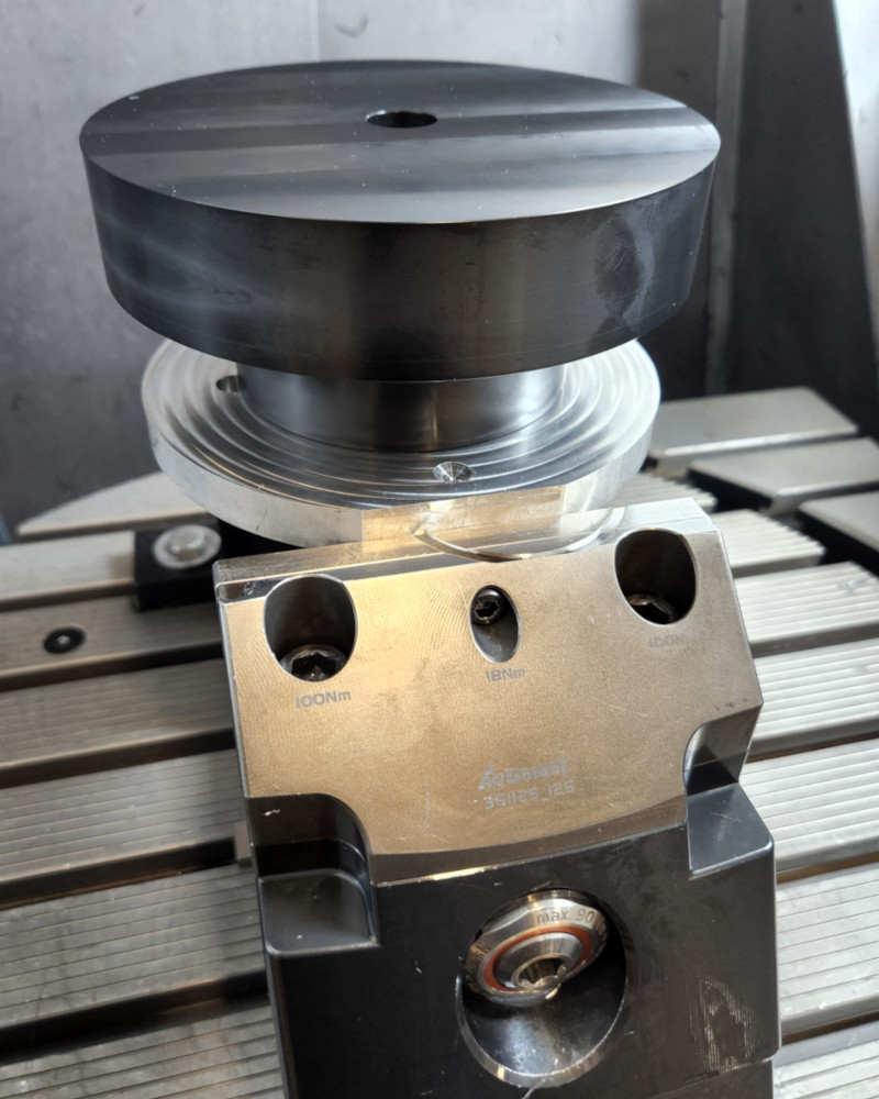
Stacked like a cake, ready to go!
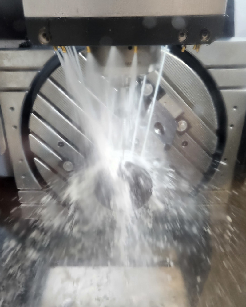
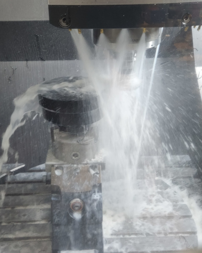
This part was a little stressful. Like I said before, the drill I had to use was longer than a standard drill and had a small diameter. After confirming the drill would run without issue, I let the rest of the operation run at full speed.
After about an hour, the part is finished! I’m not done quite yet. I had to deburr the part.
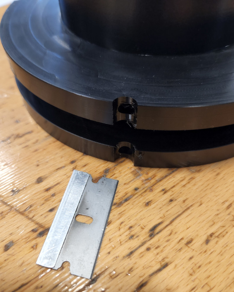
I’ve found the best way to deburr plastic parts is with a sharp razor blade. You just have to be careful!
Files
I can’t link the Fusion files, again, they’re for work, but here are the programs. They are for a Heidenhain controller, so there is a mix of G and M codes as well as conversational programming specific to the controller.