5. 3D Scanning and Printing
This week is all about 3D scanning and printing!
Finally Something Familiar
I love 3D printing. I’ve had an Ender3 Pro for a few years now, and am in the process of getting an Ender3 v2 from a friend. I’ve had few problems with them, and, considering the price point, have printed beautiful parts that require little post processing. I highly recommend them to anyone who wants to start 3D printing.
I also have a 3D printer at work, a Raise3D E2. It’s quite expensive printer produces very nice prints, when it works. I learned how to completely disassemble and fix extruders thanks to how often something went wrong on it. But as I said, when it works, it works really well.
Designing a Test Piece
I have the advantage of being a machinist, and I see some pretty weird parts every now and then, the kind that have you scratching your head, wondering how someone designed it. A lot of times, we have to get rather creative in how we machine the parts, either by using multiple machines, various workholding, and/or fixtures. But every now and then, a part still comes around that I just don’t have the capability or correct machine to make.
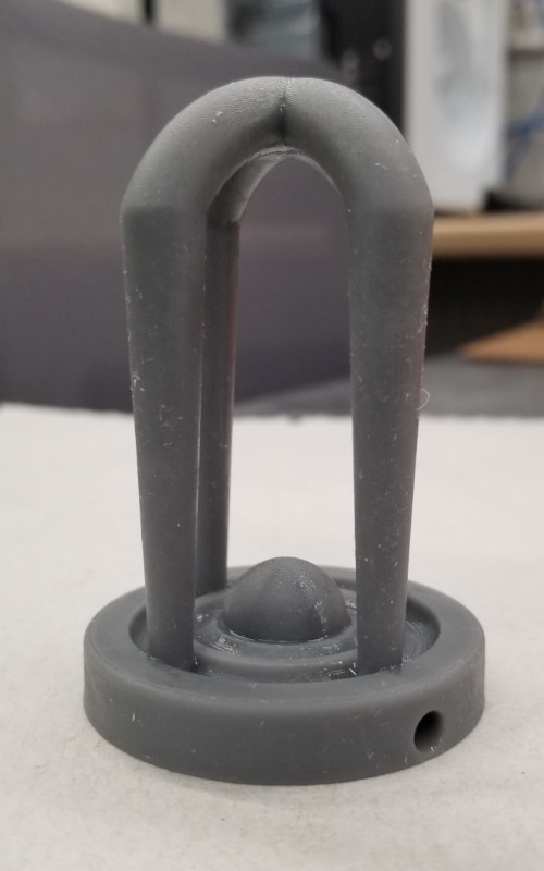
I tried to design something that would be difficult to make with the traditional machining methods, something that I would look at the print for and almost instantly get a headache. I think this should do it.
Hello Fusion, My Old Friend~
I decided to try out a bunch of different build options that I don’t often get to play with. This included using the revolve, loft, and sweep features as well as the sphere option.
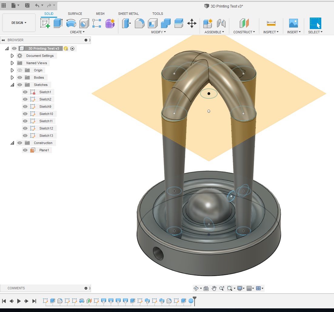
A lot of the features required their own sketches to reference. The top section of the print required an additional plane to be offset from the top plane.
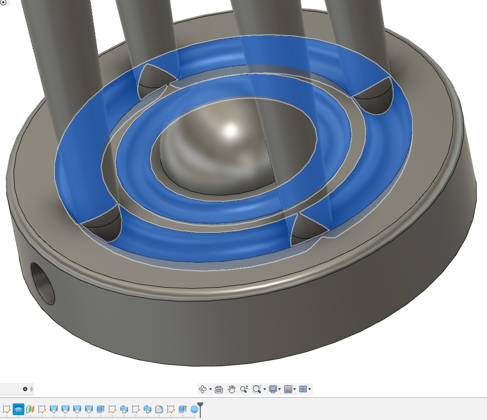
One feature that can be an annoyance is a channel. These usually require a ball endmill, or an endmill with a round tip that is a specific radius, to machine. In addition, I also added a sphere in the center, another feature that requires a ball or bullnose endmill. A bullnose looks almost identical to a standard square endmill, except the corners have a small radius instead of points.
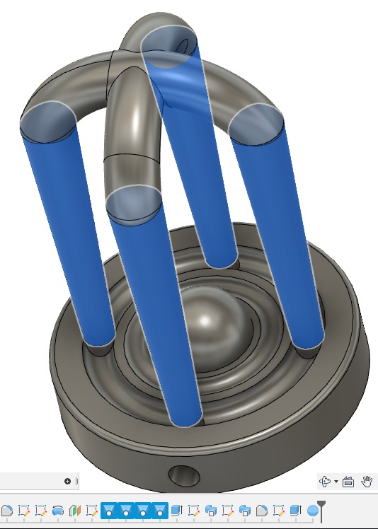
This feature required the offset plane. I used that plane to create another sketch with slightly larger circles directly above the circles on the lower plane. Loft requires a start and end point, and then it creates the feature between, in this case, the pillars.
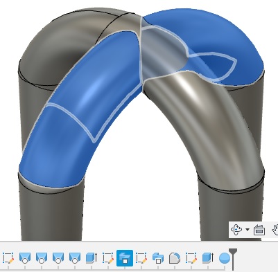
Last, I wanted to create arches connecting the pillars, but I wanted them to cross. I created another sketch with a simple arched line that connected two pillars across from each other. This line became the path required for the sweep feature. It is similar to loft, but it needs a designated path between the two features. In this case, tops of the pillars were the two features, and the arch line was the pathway. I didn’t use any set radius or measurements, so the two arches are slightly different, though it’s not very noticable.
Once I was satisfied with the part, I had to export it as a mesh file that the slicer can recognize. I went to the internal menu inside the design space and expanded the “Bodies” folder. Since there was only one part made, there is a single body in the folder. After right clicking on the body, I selected “Save As Mesh” from the options. In older versions of Fusion, there was an additional option to “Save as STL”, but it looks like this was consolidated under one option.
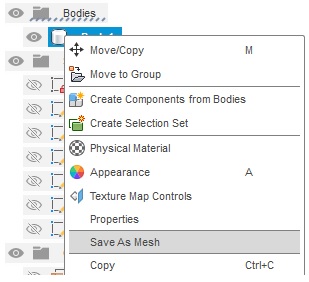
Once selected, I went through the selections on the popup menu. Under format, I selected “STL (Binary)”, made sure the units were correct, and left all other options on default. I hit confirm and saved the file where I could find it again.

Pop it in the Slicer
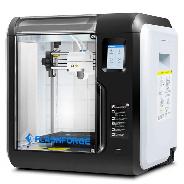
The printers in our lab are FlashForge Adventurer 3. They’re not bad printers in terms of print quality, but there are a LOT of things I do not like about them, but we’ll get to that.
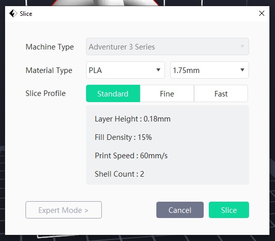
The printers use FlashPrint, their proprietary slicer. It looks similar to Cura and ideaMaker, but a more simplified version of both. I imported the STL file of my part and left all the settings at default. This print doesn’t require any additional supports or adjustments, and sits flat on the print bed.
After slicing the model, I did a quick check through the layers to make sure nothing weird popped up. I started doing this when I had parts that had features that had the potential to fail, or if I needed to adjust supports to account for a new layer that started away from the main print. It’s also fun to scroll through the layers and watch how it builds to the finished product. Then it was time to send it to the printer.
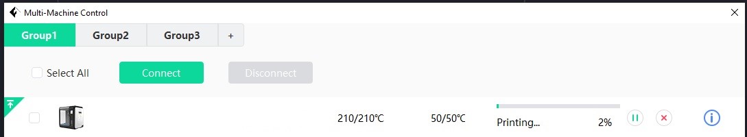
We have 15 printers in the lab, and they’re all assigned an IP address that can be accessed from any computer in the lab. It’s a very convenient feature especially when you’re setting up multiple prints. This way you don’t have to go to each individual printer with either a jump drive or a laptop and set them up.
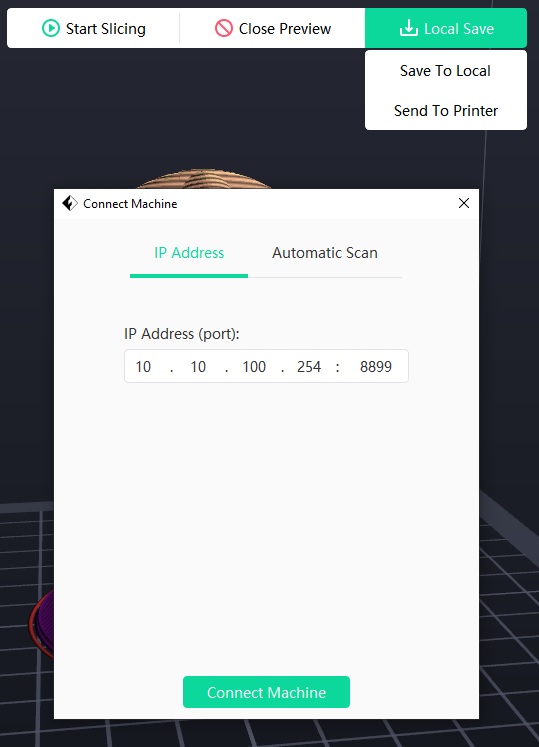
After trying to send it to the printer, it initially failed. I double checked that the printer was connected and didn’t have any errors, and tried it again, and it recognized the printer. I’m not sure what caused the blip.
First Print with FlashForge
Once sent to the printer, I heard it start moving, so I went around to watch. As a habit, and I’d argue good practice, I always watch the first layer at the very least. If the first layer adheres well and there are no other obvious issues, then it’s usually safe to leave alone.
After heating up, the nozzle came completely down on the print bed and started printing. I wasn’t expecting this, and it scared me at first, but it seemed fine. It must have some sort of calibration or probe in the housing for the nozzle itself (it’s actually in the bed, spring loaded), but I can’t imagine it’s good for the end of the nozzle to do that over and over. Unfortunately, it immediately had a filament error, which confused me because it was printing fine.
I checked the roll, and realized the filament broke at the entry point of the extruder. The printer must have a filament sensor as well. I tried to change the filament to get the short piece out, then load the roll again. But that didn’t work. The filament didn’t come out the end, probably because the short piece got caught on the edge inside the extruder, so the filament was ground down at the gears, which means it won’t have material to grip to move it forward or backward.
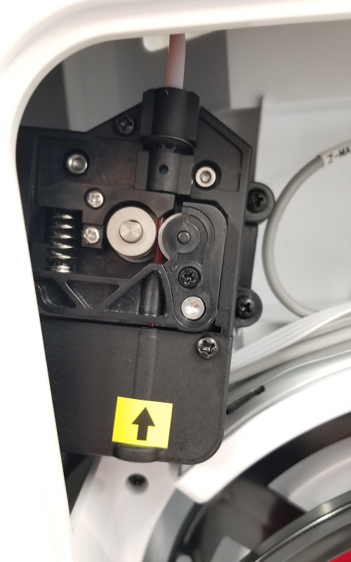
The printer design is absolutely awful. I cannot get to the extruder to actually clear any jams as it’s tucked behind the housing. I have plenty of experience fixing jams and disassembling/reassembling extruders and hot ends, but I didn’t want to start messing with the printer without permission. It probably wouldn’t have taken very long, but I didn’t want to waste time on it either.
Later, one of the professors in charge of the lab came in and I asked him about the extruder and how they fix that issue and others. There are a few ways to work around the problem, but he had tried to take the printer apart to get that particular housing out of the way and found that the only way to get it off was to break it. It sounds like the tabs connecting the panels weren’t made to come apart once assembled, which is a HUGE design flaw, and yet another reason to avoid these printers.
The second issue was the filament itself was cheap and had a tendency to absorb moisture very quickly, which makes it brittle. PLA, the filament that’s loaded in the printers, is easy to dehydrate, usually with a special machine, using desiccants, or with a toaster oven on low heat. However, it’s a hassle to do over and over. It can take hours to get the moisture levels back down, and the rolls are bulky, meaning you can’t dehydrate multiple at a time due to space constraints.
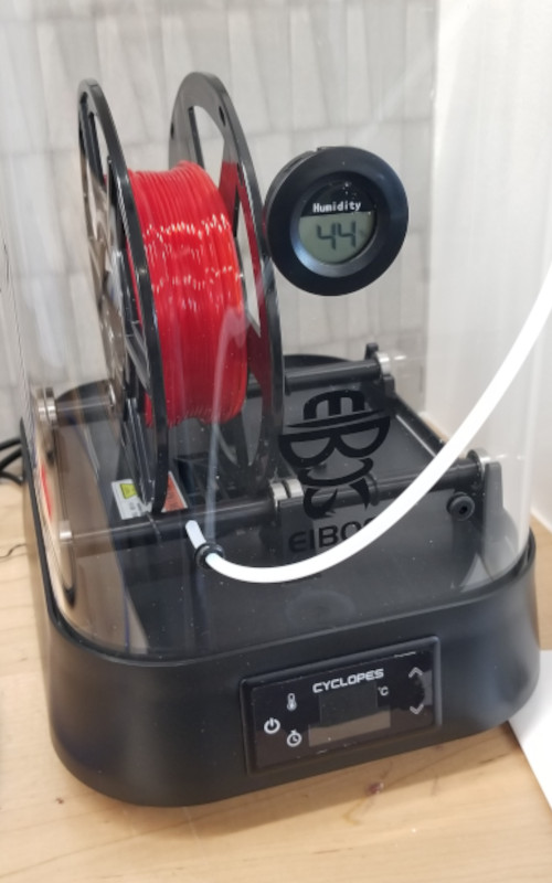
Third issue is with the rolls themselves. They’re more narrow and smaller in diameter than standard rolls, so these printers require their own proprietary filament in order to fit in the housing. It’s annoying at best and a deal breaker at worst. A majority of printers on the market forgo the housing entirely, which lets you use a wide variety of filament types without worry. In order to get better filament, we’ll have to either save the rolls when they’re used and reroll them with the new filament, or 3D print a roll file that screws together and scale it to the odd size, or design a new roll entirely.
Honestly, it’s incredibly frustrating how often printers are ordered without consulting someone who has ACTUALLY used a 3D printer. I would never buy these printers for myself, and would never recommend them to anyone else.
Luckily, the second printer seemed to heat up very quickly.
The initial line was a half circle that started with a thick line that tapered, testing the flow maybe? Then it began printing a raft. I’m not a fan that it doesn’t have an initial wipe pass, where it runs a line along one side to make sure the filament is flowing properly, and to get rid of the filament that has oozed out of the nozzle while heating. Instead, the ooze became an artifact. Granted, it is on the raft, but without a raft or brim, that could be an extra nuisance on the print itself.
After the first layer, the print seemed to be doing well, so I moved on to work on other things in the two hour estimated print time.
Flashforge doesn’t look like it factors in the raft time in its total estimation. While printing it, the time on the display did not change. Other printers factor this in, as it’s part of the total print time. If this was used to produce multiple parts back to back, then the 10 mins it takes to print wouldn’t be factored in, throwing off part estimations by a good bit. I’m also not sure if it factors in the raft when it estimates the amount of filament used. This can be another annoyance and potential headache when trying to estimate how many prints you can get out of a roll, or if you’re close to the end of a roll and need to change out.
After watching it for a little bit, I noticed that the time didn’t seem to tick down very consistently. I watched the timer for a few minutes, but the display only changed by one minute. I should have started my own timer to check the accuracy, but I’ll do that next time.
Results
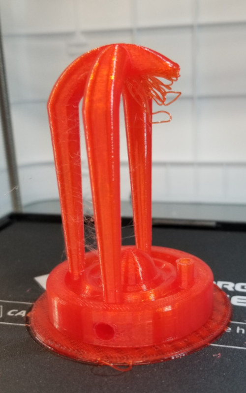
Not great.
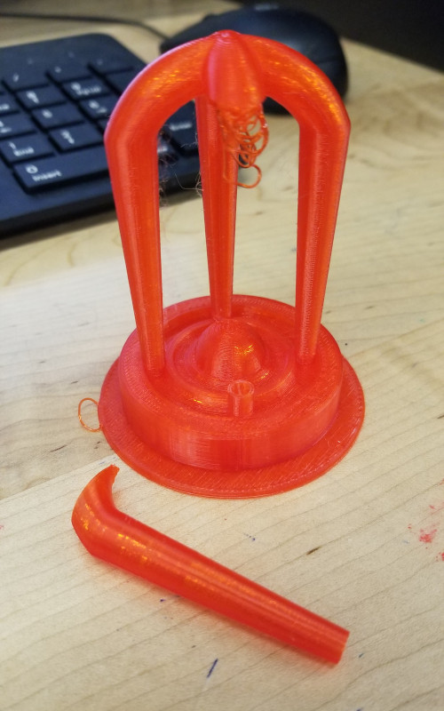
At some point one leg snapped off. I’m not sure what happened, but I think the lip started to warp up with the heat (not an uncommon issue) and either the nozzle or the air duct caught it and snapped it off the part. It does give me a good view of the infill, which is very thin. 15% is fairly average for display prints, so I wasn’t worried about how sturdy it would be, but the infill looks like it’s stretched thin, as though it’s stringing instead of actually extruding.
There are a lot of strings between the legs, but looking at the default settings, I’m not surprised. The extruder is set to 210 C, which is right at the top of the recommended heat level for PLA. This means that filament is more likely to continue oozing while the printhead travels between print locations, creating wispy strings.
The raft is extremely thick, and is completely adhered to the part. I didn’t want to use too much force to try to get them apart; the legs would probably break before I got the base off. The first layer of the raft looks really good though, very even and flat.
Hopefully we can find some good settings with these printers when we do the group portion.
Additional Attempts
I’ve had an Ender3 Pro for a couple years now and love it. Recently though, I had a jam in the extruder, and in the process of changing the nozzle, managed to break it instead (oops). While debating about what upgrades I could buy in the process of fixing the printer, a friend of mine offered to sell me his extra Ender 3 V2, which is the next generation with many of the improvements I was looking at for the Pro. So of course I bought it.
Cura Slicer
I used the same file as before and imported it into Cura, a free slicer from Ultimaker. It’s easy to use and had a very clean and simple layout that’s not overwhelming for first time users, but also allows for a ton of tweaking in the advanced features. It’s not as powerful as the PrusaSlicer, but one advantage is the number of printer profiles that are already available to use, including the Ender 3.
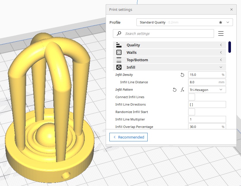
I tried to get the settings as similar as possible, but the infill pattern was slightly different as Cura doesn’t have the same patterns. For the record, FlashPrint has three options, Cura has 14. Prusa has even more.
I saved the file to the microSD that came with the printer and started the print up. The time was roughly the same at just over two hours.
Ender 3 V2
The Ender does not have a self leveling system for the bed. It can be adjusted by hand using four knobs located at each corner of the bed, and requires either a feeler gage or, more commonly, a piece of paper. To level it, I had to slide the paper between the nozzle and the bed, and adjust the height until there was some resistance when I moved the paper back and forth. Then it’s a matter of moving around the bed until each corner has the same amount of resistance. It sometimes takes a few rounds to get it dialed in, and it can be time consuming and frustrating at times, especially after moving the printer. Creality, the makers of the Ender, has since added a touch probe option that attaches to the side of the hot end, the block that holds the nozzle, and connects directly to the motherboard. I haven’t tried it yet as I’ve had really good results with the paper method, but for first time users, the touch probe can save a lot of headache.
There are also multiple test prints that people have developed to help level the bed. The one I use is similar to this Ender 3 Level Test. After printing, you can adjust the knobs in the area where the print has problems. If the filament is too thin, or looks transparent, then the bed is too close and needs to be lowered. It is not allowing enough filament to extrude from the nozzle. If there is no or poor adhesion, or the lines are rounded instead of wide and flat, the bed is too far from the nozzle and needs to be brought closer.
The type of print bed can also be a huge factor in how level it is overall and how easy it is to level. I have a glass bed on both of my Enders. My original Pro had a spring steel bed that was held on with magnets, and it worked great for a while. One of the selling points for this type of bed is the ability to remove the bed and bend it slightly, popping the prints off easily and quickly. However, it is also the first thing to cause problems down the road, as all the flexing and bending can warp the steel. Even a slight bulge can cause a print to fail. The glass bed is nearly perfectly flat, which allows for excellent adhesion, but that same adhesion can make it extremely difficult to remove the print. Luckily, once the bed cools, the prints usually pop right off due to slight contractions in the material.
All of the above is just a long winded way of saying the print turned out really well and popped right off the bed when it finished.
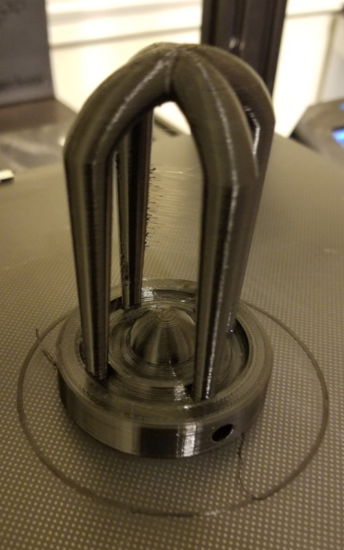
I’m really happy with how it turned out, and was a great test to make sure I set the printer up correctly. Now I can carry on with my print queue.
Resin Printing: PreForm
Last semester, I took one of our old resin printers in order to clean it up. The school bought five new FormLabs 3BL printers, and the older FormLabs Form 2 were set aside. Unfortunately, the printers had been neglected and were filthy, with resin and dust all over them. Resin had been left in the trays for months, and they hadn’t been turned on in just as long. Luckily after a bit of TLC and some new accessories, the printer came back to life and now has its own place in the lab.
Nick hooked it up to its own computer, and I got to be the first one to use it. I was super excited to get to use it; I have a couple friends who have resin printers, but I had never used one myself, for various reasons, but they make absolutely beautiful prints.
Setting up a resin printer is very different from a FDM printer, but the software side is pretty much the same. Physically, the printer must be level, or the liquid resin will all move to one side, leaving little or none in the opposite direction, which is a surefire way to have a print fail. FormLabs has a tool that can reach under the printer to the feet for easy leveling, but it has long been lost. I’ll have to remember to print a replacement later, but in the meantime, I simply lifted the printer to make the adjustments, and allowed it to settle before making another movement. The printer has an option in the menu that shows how level the printer is, so it was a matter of trial and error to get the dot lined up in the acceptable range. The printer does give suggestions for which foot to move, which is very helpful.
FormLabs has its own slicer software called PreForm. Again, the setup looks very similar to Cura. The program is very streamlined and simple to follow. Someone with very little experience can easily set up a print with a high chance of success.
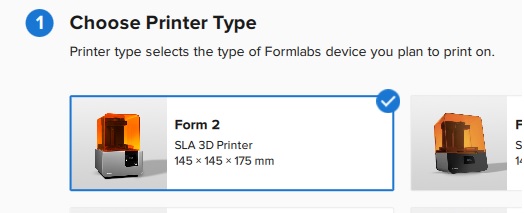
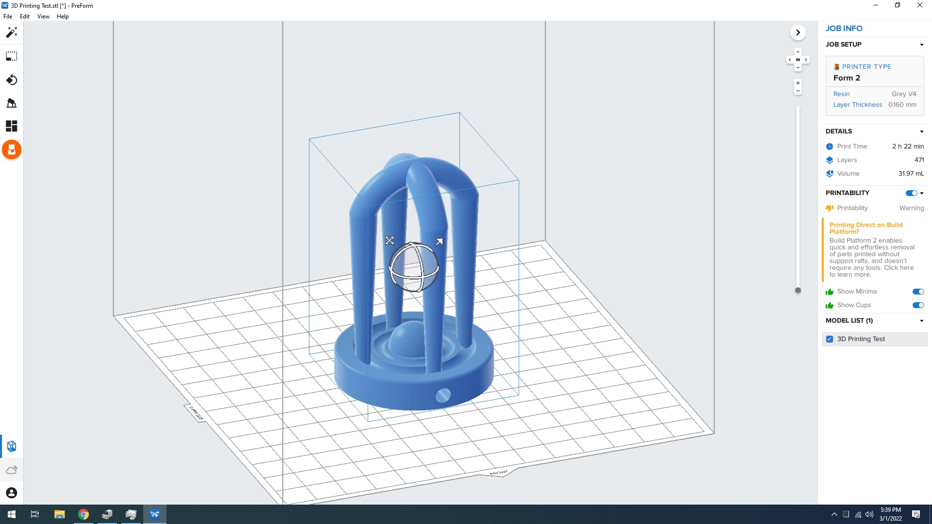
The menu is very clear, and I’m a big fan of the pictures to make it easy to select the correct printer. That way, even if someone doesn’t remember the name, they can still select the right one. A lot of printers have names that aren’t very easy to remember.
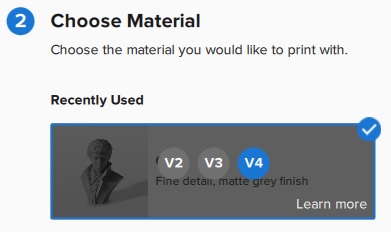
This information is found on the cartridge that is used with the printer. If it’s already inserted in the printer, it’s located on the top as well.
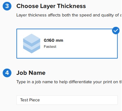
Since I didn’t have a lot of time, I chose the lowest resolution, 0.16mm, which is close to the other two prints as well. With this option, the print time was 2 hours and 20 minutes. The next highest resolution bumped the time to over four hours. Then I added the name and finished.
After setting it up, I sent it to the printer as Nick had set it up directly to the computer. For all my excitement, the next part was a bit boring. The printer had to fill the tray and heat up the bed, and it took longer than I expected. I didn’t have a reference to know how long it would take, so the actual printing started later than I anticipated. After the first couple layers, I was satisfied that it would work, and went to work on other projects.
Just for Funsies: FormLabs Form 2
The part finished with no issues! I was a bit worried, especially since I had been the one to clean it up and this was the first use of it since. The print looks great though, which was a big relief.
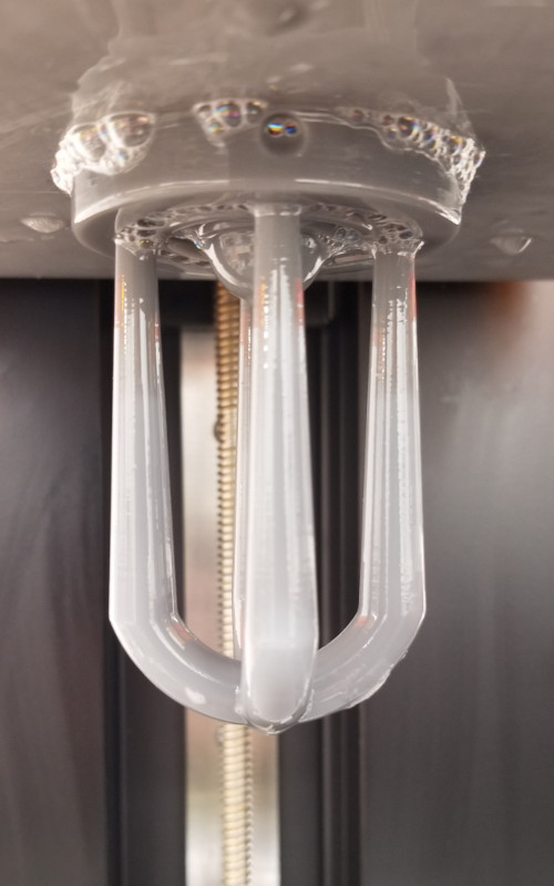
I was a little concerned about the bubbles on the bed and print, but figured it was just excess resin.
The next steps are very different from the more common FDM printers. With the Ender, I can pop the print off the bed, remove any supports, maybe touch it up with some light sanding if needed, and be done. With resin, there are certain steps that have to be done in order to have a successful result. Printing it is just half the battle.
I’ll admit, I didn’t plan this very well, so a lot of the hunting around was partially on me, but the fact that nothing was clearly set up for the resin printers is also a bigger issue.
To clean up a resin print, you need gloves, paper towels, isopropyl alcohol, a container big enough to hold the alcohol and the print, and a curing station. To get the print off the bed, you also need a spatula or putty knife of some kind, essentially something thin enough to get under the edge of the print, but strong enough to pry it up if necessary.
I spent more time than I should have looking for what I needed, and in the end had to improvise at times. I ended up using a putty knife from a random toolbox to get the print off. Then I couldn’t find a container to wash the print off, so I wiped as much of the extra resin off as I could.
It was only after going through all this that I found out that we have a post processing room that has some of the necessary tools for resin prints. I knew of the room, but didn’t know what was in it because it’s always locked (an issue that will hopefully be fixed in the future). Luckily Garrett had a key. Turns out, there was a wash station and a curing station, plus a sink, paper towels, and a small work surface.
The wash station was designed for the smaller FormLabs, and is able to hold the print bed in the same orientation as the printer, but also has a basket for loose parts.
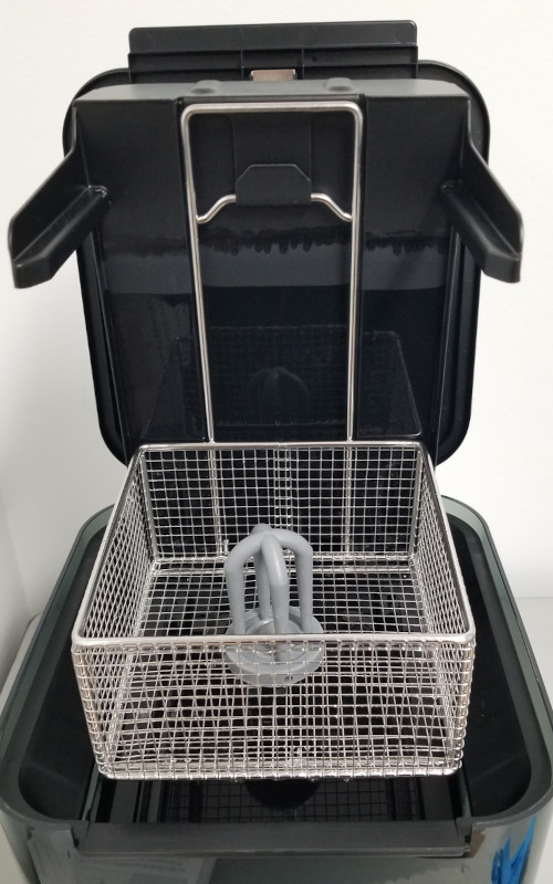
It would have saved me so much time and effort if I had known about this earlier. I ended up chipping a part of my print while trying to get it off the bed, when this would have done the job easily.
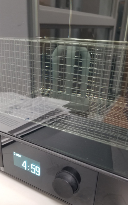
The controls on the front panel were simple to use and easy to follow. I set the wash timer for five minutes and let it run. If I had more time, I would have let it run longer, but the part doesn’t have a lot of nooks and crannies either, so this was probably sufficient.
After the wash, I moved the print to the curing station.
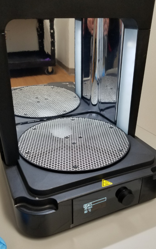
Most resins require UV light to cure properly. Before the curing process, the surface of the print feels gummy; not quite sticky, but definitely not set. Curing basically finishes what the printer started and solidifies everything into one piece. This is why it’s important to wash and remove any excess resin. If left, the resin will cure wherever it’s sitting, whether dripping down the sides, pooling in creases and low spots, or just adding an extra layer of material where it’s unwanted.
Important note: Resin will start curing even if you never use a dedicated station or setup! A curing station speeds up the process, and emits said light evenly across the surface, but the print will also cure if just left out on a window sill. It will just take longer and may be more set on one side than the other.
This is also important to remember for the print reservoir!! Every time the lid is opened, any resin left in the bed gets exposed to light, and can start to cure. That’s why you must always remember to close the lid anytime the printer is not in use. The colored plastic cover is designed to keep the particular UV wavelength from reaching the liquid resin.
Final Results
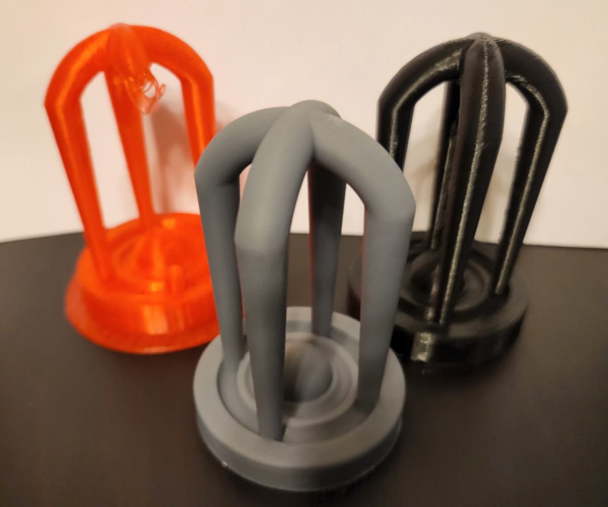
The resin finish is far and away the best, but with the right settings and printer, a standard FDM can give some really nice results too.
3D Scanning
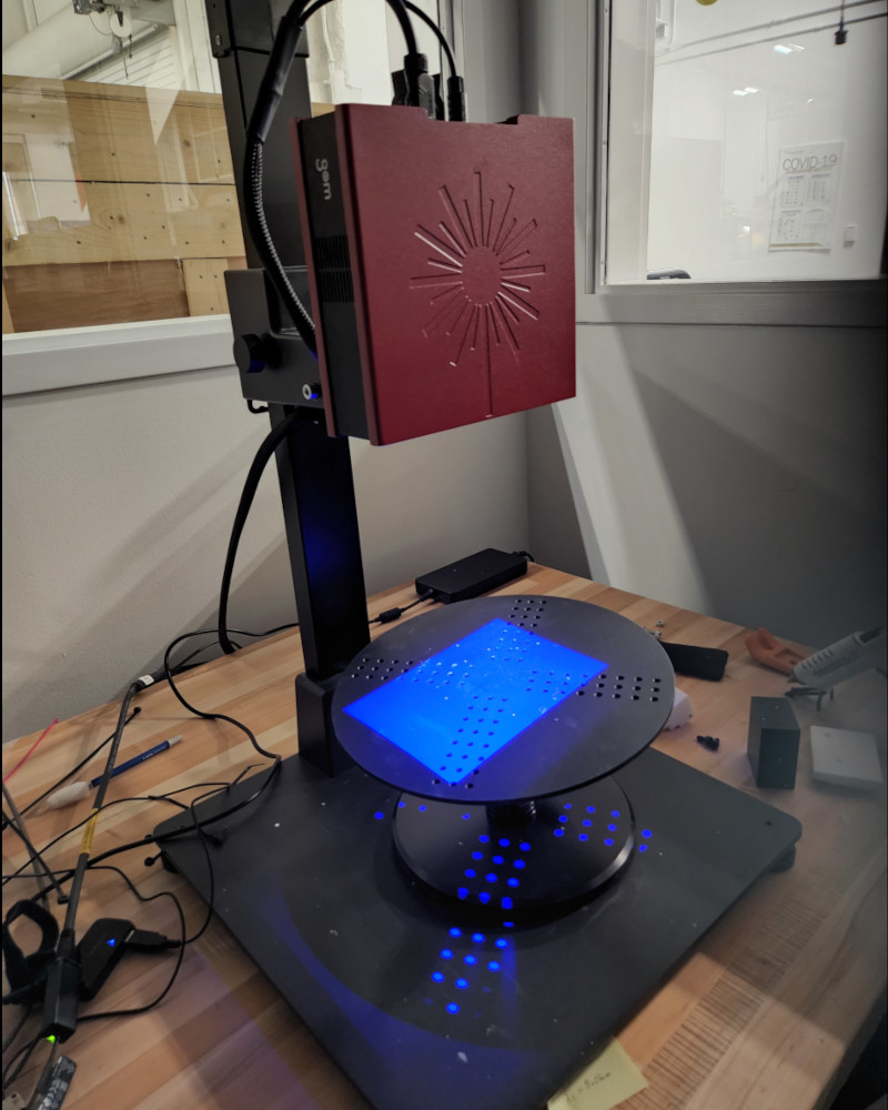
I didn’t know we had a 3D scanner. Apparently it’s in our metrology lab. I had seen it before when I was a student, but didn’t realize what it was. Our scanner is a GOM. It’s set up in it’s own corner of the lab with a dedicated laptop with the software already loaded.
I decided to use the resin print as my scanned item. The goal is to eventually print the version that is generated from the scan and compare the two. Because the resolution for the resin in so small, I’m curious to see how well the layers are picked up and translated back into a model.
When setting up a part, only need to use dots if the part needs to be picked up and moved When moved, the next position needs to be able to see at least four dots from the previous position as reference to relocate Since my part is the same all the way around and the base is flat, it doesn’t need to move. The table is able to rotate and pick up all the sides.
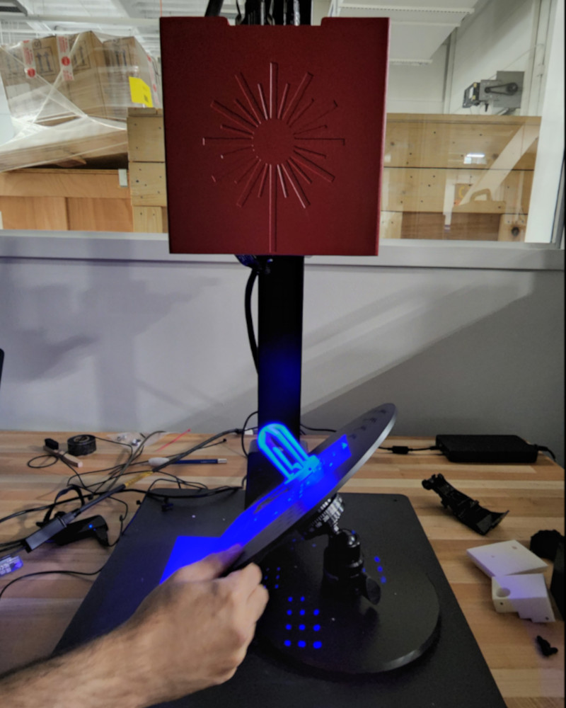
Set the part in place on the table with a dot of hot glue. Put it on the part first then press onto the table, the metal cools the hot glue down too fast, will be solid by the time you try to add the part too. The lab is also kept cool, at the designated proper metrology lab temp, aka cold.
The newest version that we have is Gom Scan 2018. Open it up, and from there start a new project.
The initial picture in the camera will look red. This means the part is overexposed and needs to be reset. Along the bottom of the screen, the menu has an icon with nine dots in a square, this recalibrates the exposure. If it’s still overexposed in places, use the single dot to correct the exposure.
Once set, flip to the second screen and hit the spacebar to scan. Important: Do NOT touch or put anything on the table while it is scanning. It is extremely sensitive and can cause an error, will stop scanning
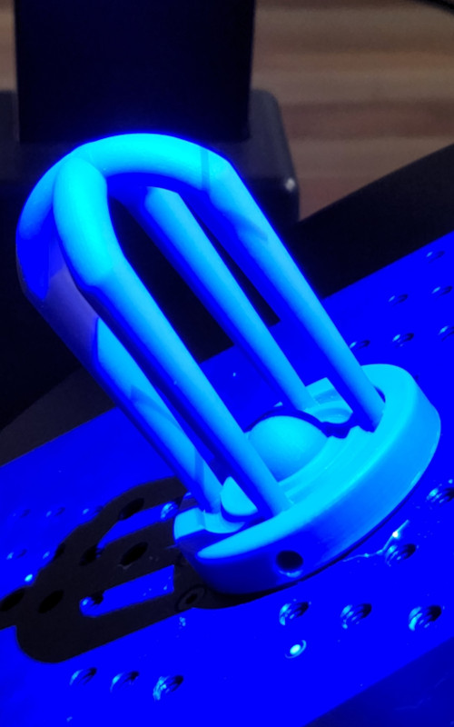
Had some trouble picking up the part initially. The scanner has issues with shiny surfaces, so we thought the matte gray surface of the print would work. After a few scans with only a few spots, it began to pick up the surface The scans show up on the bottom left, and if it’s a bad or subpar scan, will have a yellow icon next to the name. A good scan has a green checkmark The table spins and is able to tilt, so after tilding the part and rotating it between scans, was able to pick up the part much easier.
Once we had a decent number of good scans, went back and deleted the bad scans. Every time a new scan is created, all the previous scans have to recompile. Each scan is huge, with multiple gigs of data, so it is beneficial to delete any unnecessary or bad scans.
After many scans, the form starts to take shape on the screen. Initial thoughts, it looks really good. Anything in the scan that is red is where it hasn’t been scanned and/or can’t see. The underside of the arches was all red since it can’t tilt far enough to see under, or the table would get in the way.
Next step is to clean the model. Usually there are extra bits and dots mixed in with the model, so need to remove them before saving/exporting for use.
Click and drag over the dots to highlight them, the remove/delete May take a minute to recompile the data, so had to be patient. Repeat as many times as necessary or until satisfied with the results. Can also create a plane and delete anything on one side, so created a plane at the bottom of my part, where it’s flat, and deleted anything below it.
Next, convert the scan into a usable STL/mesh file. Click “Acquisition” then “Polygonize” This is compiling all the data into a usable model, so it will take a few minutes. More patience needed.
Group Project
The information about this week’s group project can be found here.
Since Garrett created so many different print varieties, my job was mostly checking on the prints to make sure they finished and to take pictures of the results. Unfortunately, since the printers are so finiky, it took a bit of trial and error and starting and stopping to get all the prints to finish.
Files
Below are the files for my 3D print:
- Fusion 360: Test Print
- STL File: 3D Printing Test
- Cura Post for Ender 3 V2: 3D Printing Test
- PreForm Post for Formlabs Form 2: Since this was sent directly to the printer, I don’t have a saved copy. Will update when I get in the Fab Lab again.